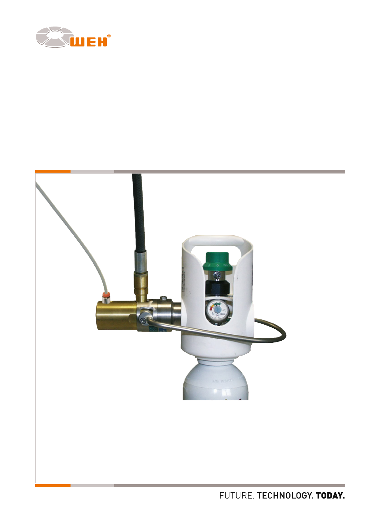
Operating instructions Date: 09/10
Type TW102
Page 8
D-2010/09/00719-0-3
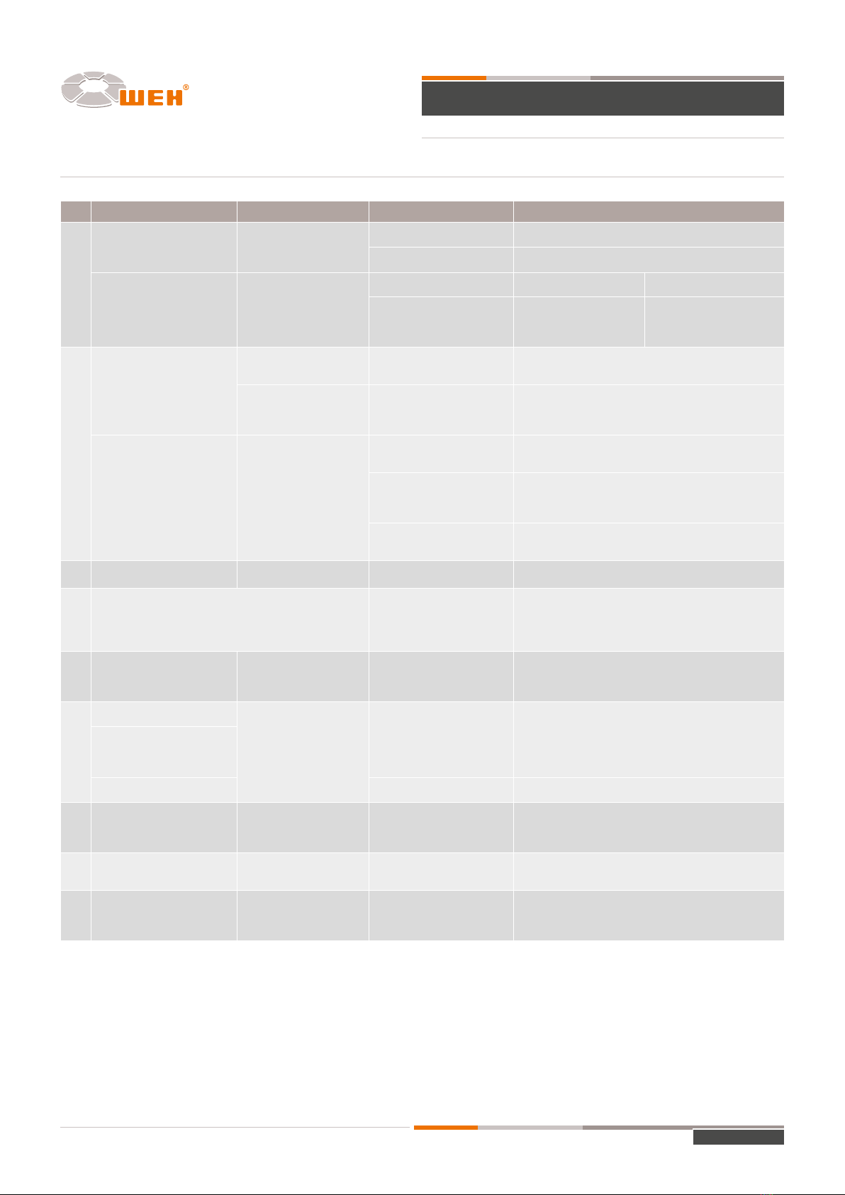
8 TROUBLE SHOOTING | CORRECTIVE ACTION
No� Fault can be recognised by possible cause Remedial measures (Note 6�9�4!)
1
Gas leak when starting fil-
ling procedure, decreasing
with increasing pressure.
Feel for leak when filling
starts or the sound of
escaping gas
Improper connection Stop filling, repeat connecting procedure.
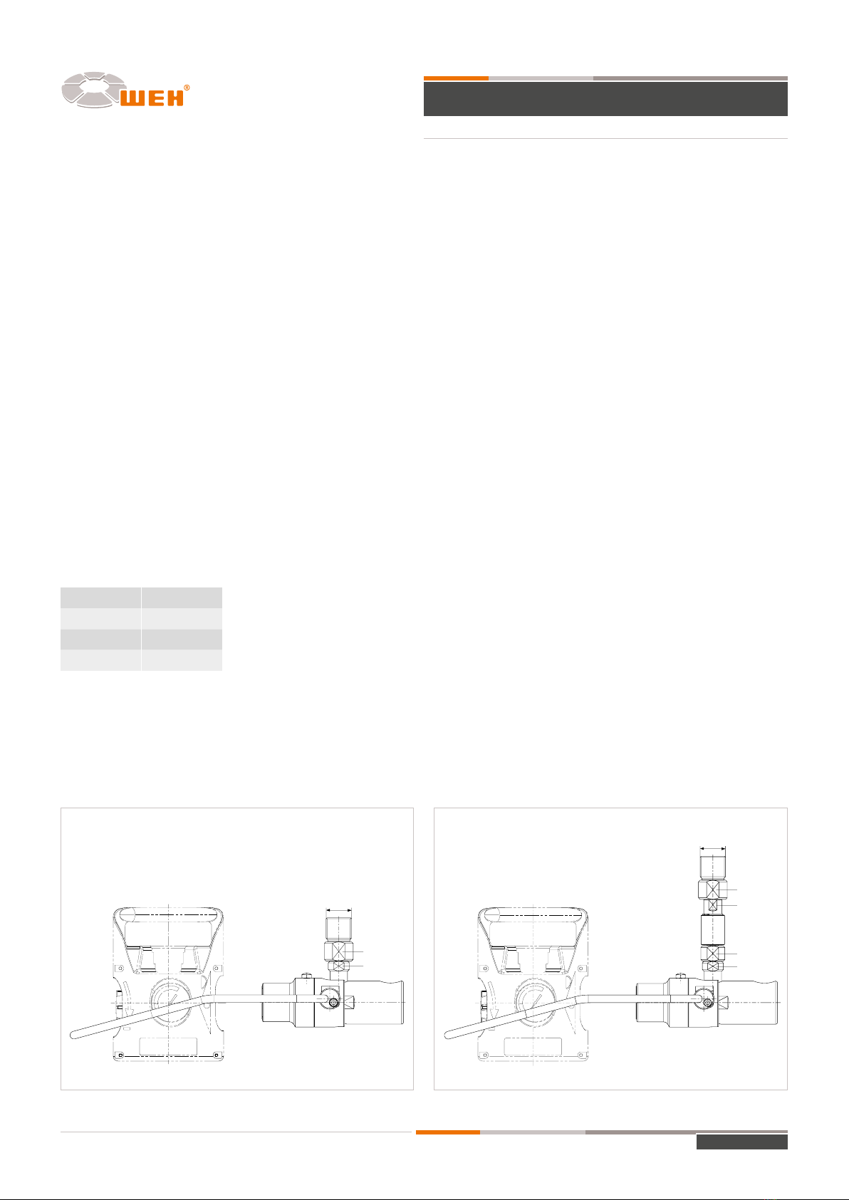
Inlet too rigid E.g. attach flexible hose, swivel joint type TD1
Increasing gas leak when
pressure increases. Blow-off sound
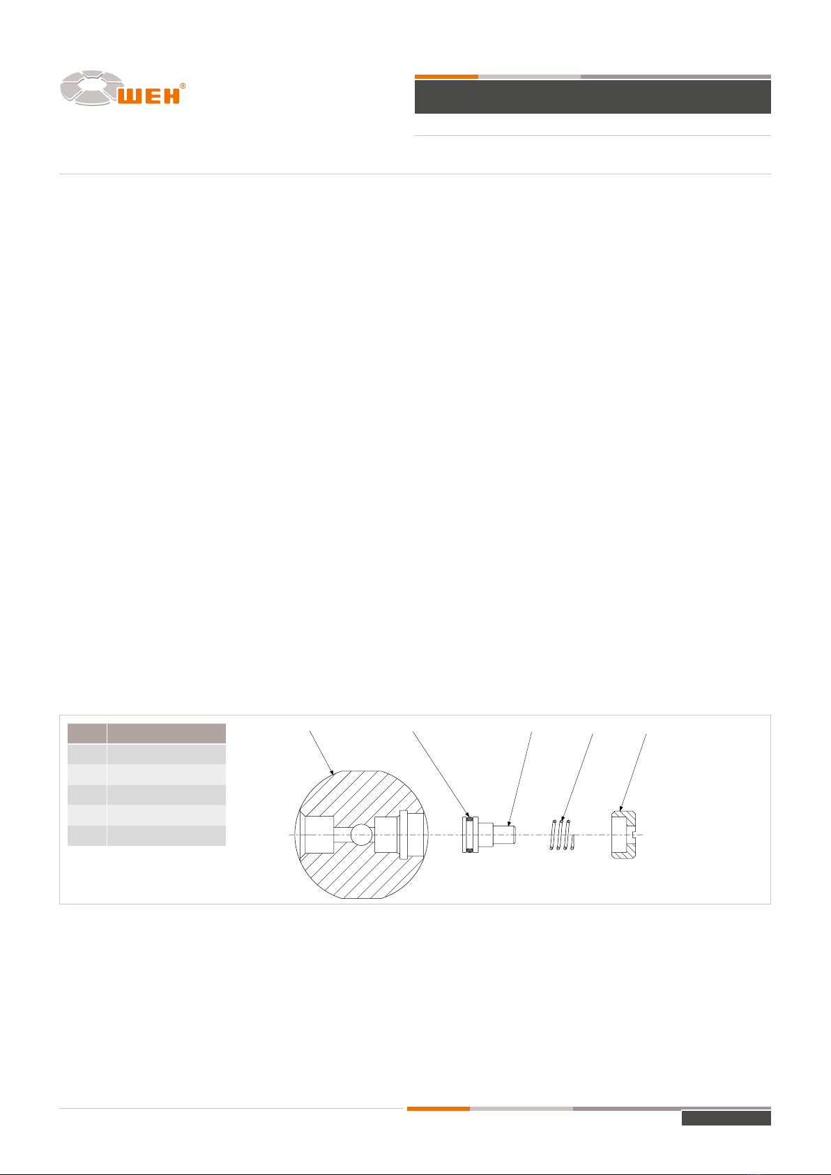
Faulty front seal, pos. 7 Stop filling. Replace front seal pos. 7
Valve thread damaged
Decide whether filling
should be stopped or
continued.
Exchange valve
2
Safety peg does not pro-
trude during pressurization
Feeling at outlet or visual
inspection Safety peg distorted. Stop filling. Change safety peg (see 6.5)
Filling pressure must be
between 15 and 20 bar
for peg actuation
Insufficient lubrication /
dirty
Lubricate safety peg or replace connector before
proceeding with filling and service.
Safety peg does not move
back into the body
Visual inspection.
Operating loop cannot
be moved to opening
position.
System not depressurized
sufficiently.
Check if cylinder valves are closed.
Proceed to depressurize.
Safety peg seized because
of insufficient lubrication.
Lubricate safety peg.
Only lubricate oxygen connectors with grease approp-
riated for oxygen
Safety peg seized, or
distorted
Push safety peg into connector by hand or with a tool.
Change safety peg (see 6.5).
3Cylinder cannot be filled Filling does not start Pilot pressure not activated Apply pilot pressure
4
Deformation or distortion of sliding sleeve or operating
loop, connecting pieces thus difficult to operate, leaking
of body or fittings
Contact with cylinder caps
when moving pallets in and
out.
Improper repair
Replace connector immediately and return to manu-
facturer
5
The socket head screw
securing the cam of the
operation loop is loose
Loose screw Fittings are loose Change screw
Tighten the screw to 10 Nm
6
Connecting thread leaking
Blow-off sound
Fittings are loose
Tighten the fittings to max. 20 Nm. Each fitting has
to be held with a second wrench. If necessary open
fittings and replace joint by using new WEH original
joint. Do not use Loctite
Swivel joint leaking
Safety peg leaking Dirt, wear of inner joints Change safety peg (see 6.5)
7Jaws of collets have not
expanded properly
Connector is too loose,
can be moved within the
valve thread
Wear
Check the cylinder valve first with a thread gauge. If
thread is ok - replace connector; if thread is faulty
replace cylinder valve.
8Less than 4 threads are
engaged
Threads showing out of
the end of the valve
Wear of connector cams;
wrong cylinder valve Replace connector or check cylinder valve.
9
Faulty connecting thread at
cylinder valve, obviously
loose.
Connector is loose des-
pite proper connection
Wear of connecting
thread of cylinder valve.
Separate pressure gas cylinder for replacement
of valve!
Important: In case of problems contact manufacturer or supplier.