Lacanche Cormatin User guide

Art Culinaire17721 132nd Ave. NE Woodinville, WA 98072 425-481-7500 Fax: 425-481-8080
Fourneau
« Cormatin»
-Do not store or use gasoline or other flammable vapors and
liquids in the vicinity of this or any other appliance.
-WHAT TO DO IF YOU SMELL GAS.
Do not try to light any appliance.
Do not touch any electrical switch.
Do not use any phone in your building.
Immediately call your gas supplier from a neighbor’s phone.
Follow the gas supplier’s instructions.
If you cannot reach your gas supplier, call the fire
department.
-Installation and service must be performed by a qualified
installer, service agency or the gas supplier.
-In the Commonwealth of Massachusetts, the appliance must be
installed by a licensed plumber or gas fitter.
WARNING : If the information in this manual is not
followed exactly, a fire or explosion may result causing
property damage, personal injury or death.
!WARNING!
THIS RANGE CAN TIP
INJURY TO PERSONS COULD RESULT
INSTALL ANTI-TIP DEVICE PACKED
WITH RANGE
SEE INSTALLATION INSTRUCTIONS

TECHNICAL DATA
CORMATIN
Page 2 of 40
Layout :
3- or 4-burner cook’s stove (Figure 1), G.N 1/1 oven (Figures 1, 2 & 3).
Description :
Cooking surface and body panels :
Enameled steel or stainless body panels AISI 430. Pressing cooking surface (stainless steel AISI 304) (Figures 2 and 3). 3- or
4- burners of different size and power individually controlled by a safety valve. Electrical ignition.
“TRADITION” model equipped with a 385 x 510 mm (15 5/32’’ x 20 5/64’’) heating plate.
Gas oven :
Enameled sheet metal. Dimensions W x H x D : 530 mm (20.8’’) x 305 mm (12’’) x 460 mm (18.1’’). 4 shelf level with 62
mm spacing, 55 liters / 2.18 ft3. Heating provided by thermostatically controlled burner, thermocouple safety cut-outs.
Electrical ignition.
Power supply : 120 / 240 VAC 60Hz.
Fig. 2
55 mm
2 3/16 ’’
350 mm
13 3/4 ’’
1065 mm
41 15/16 ’’
940 mm
37’’
727.5 mm-28 5/
8
’’
800 mm-31 1/2 ’’
430 mm-16 1
5
/16’’
34 mm
1 5/16 ’’
650 mm-25 9/1
6
’’
671 mm-26 7/16 ’’
47 mm-1 7/8 ’’
510 mm-20 1/16 ’’
147 mm
5 13/16 ’’
40 mm
1 9/16 ’’
Back space vent
(A)
Fig. 1
700 mm - 27 9/16 ’’
914 mm
36’’
768 mm
30 1/4
399 mm
15 11/
16
’’
478 mm-18 13/16 ’’
Fig. 3
350 mm
13 3/4 ’’ 55 mm
2 3/16 ’’
708 mm-27 7/8 ’’

TECHNICAL DATA
CORMATIN
Page 3 of 40
Static electric oven (option) :
Same dimensions as gas oven.
Thermostatically controlled roof and base heating elements, safety cut-out by safety thermostat.
Rating : 3400 W – Power supply : 240 Volts 60Hz.
Ventilated electric oven (option)
Heating provided by two circular heating elements each surrounding a reaction-type fan. Dimensions W x H x D : 530 mm
(20.8’’) x 305 mm (12’’) x 405 mm (15.9’’). This can optionally be fitted with an electric.
Thermostatically controlled heating elements, safety cut-out by safety thermostat.
Rating : 3700 W – Power supply : 240 Volts 60Hz.
Accessories
One drip tray, one shelf, one pastry tray per oven.
Shipment-Packaging
Unpack and check the appliance is in good condition. In case damage, note any reservations on the delivery note and confirm
them within 48 hours by registered letter with confirmation of delivery to the carrier.
Appliance Width Depth Height mm Weight Gross/Net
LG 731 G 850 mm / 33.4’’ 840 mm / 33.1’’ 1070 mm / 42.1’’ 105 kg / 89 kg – 233 / 197 lb
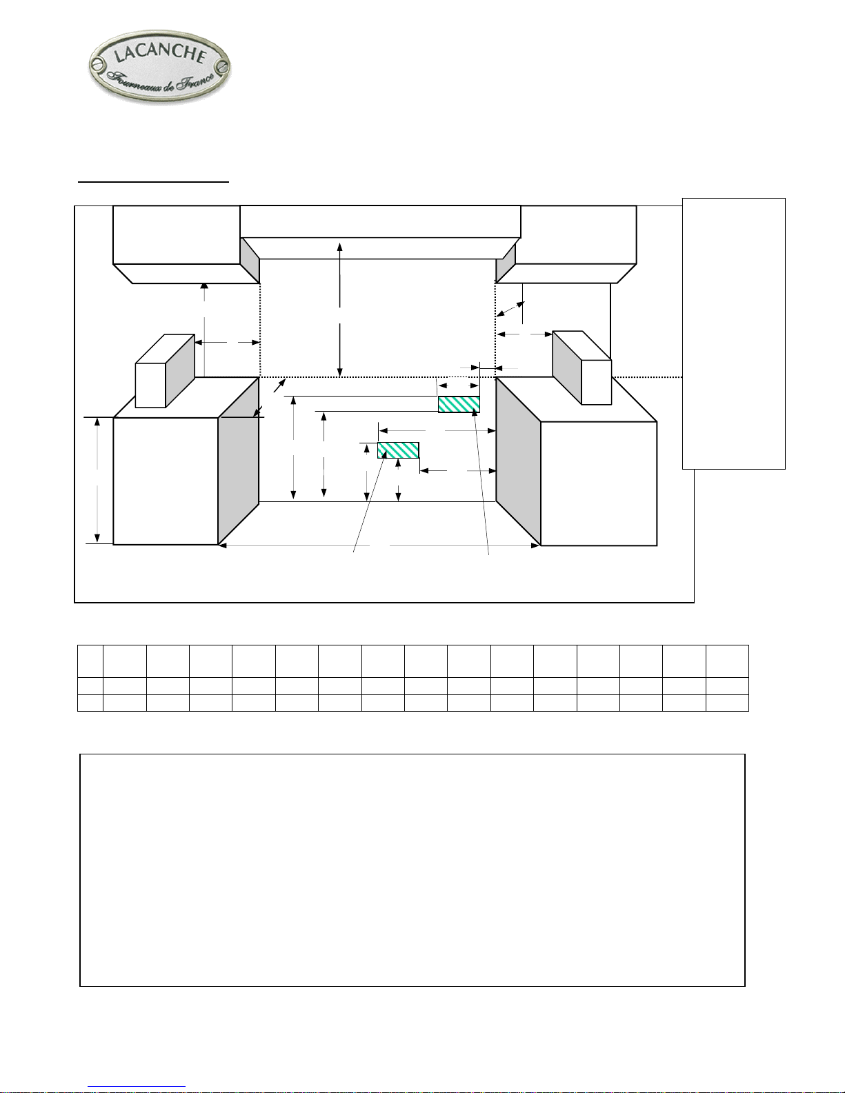
Gas connection :
1/2” ID NPT (Sch 40) inlet, on male coupling (Figures 1, 2 and 3). Sealant on all pipe joints must be resistive to LP gas.
If used, a flex gas line for the gas supply must be metal of at least 1/2” ID NPT approved by an approved certifying agency
(A.G.A., C.G.A,. etc.) in compliance with ANSI Z21.41 and Z21.69. Never use a hose made of rubber or other synthetic
material.
Gas supplying :
Appliance gas supplying can be switched, please refer to rating plate and marking at the rear of the appliance.
Electrical connection :
On terminal block at the rear of the appliance. Use flexible cord in accordance with standard N.E.C., AINSI/NEMA 70-1996
or latest edition (not cord provided) (Figures 1 & 3).
Pressures and hourly consumption :
Appliance gas supplying can be switched (table 1).
Table 1
PRESSURE 6’’ WC 10’’ WC
GAS Natural Gas L.P. Propane
Burner Btu / hr Btu / hr
Oven 13,000 13,000
Ultra fast (UF) Tradition (T) 18,000 17,000
Intensive (I) 13,000 13,000
Fast (F) 10,500 10,000
Semi fast (SF) 5,000 5,000

TECHNICAL DATA
CORMATIN
Page 4 of 40
UF SF T
I
SFF
F
SF
FF

Page 5 of 40
Fourneau
« Cormatin»
INSTALLER'S MANUAL
Appliances must be installed in a workmanlike manner in
accordance with the instructions in this manual and locally
applicable regulations.
In the Commonwealth of Massachusetts, the appliance must
be installed by a licensed plumber or gas fitter.
This manual will be handed over to the user after
installation.

INSTALLER’S MANUAL
CORMATIN
Page 6 of 40
Cabinet preparation :
A B C D E F G H I J K L M N O
mm 762 330 457 914 290 420 235 405 20 60 765 865 705 51 660
’’ 30 13 18 36 11
7/16 16
9/16 9 1/415
15/16 13/16 2
3/830
1/834 1/16 27
3/42 26
The range is a freestanding unit. If the unit is to be placed next to cabinets, the clearances shown in Figure 4
are required.
The top grate support must be 34 mm - 1 5/8’’ above the adjacent base cabinet countertop.
Min clearances to combustibles:
2 3/4’’ (70 mm) from rear of range to wall. This requirement will be met when range is installed with
factory supplied back spacer vent (or equivalent).
0 ’’ (0 mm) from sides below 36’’ (914 mm) height.
2’’ (51 mm) from sides above 36’’ (914 mm) height.
Cabinets 13’’ (330 mm) deep may be installed above the range at least 30’’ above the plane of the cooking
surface.
Use range only with factory supplied legs
NOTE: The above diagram depicts the actual location of gas and electrical connections on the range. DO NOT
place gas stub-out or electrical receptacle in these areas. Place them nearby in accordance with local
regulations.
G
C
N
Gas connection
Electrical
connection Fig. 4
B
D E
F
H
K
I J
L
M
N
A
O
This diagram
depicts the
actual location
of gas and
electrical
connections
on the range.
Place gas
stub-out or
electrical
receptacle
outside of this
area in
accordance
with local
regulations.

INSTALLER’S MANUAL
CORMATIN
Page 7 of 40
Before connection :
Check :
- Pipework is perfectly clean in order to prevent the injectors
becoming blocked and malfunctioning of the magnetic heads.
- The gas for which the appliance was set up: Rating plate and
markings.
- Cross-sectional area of gas supply pipework is compatible with the
appliance’s thermal output.
- Provide adequate air supply during use of the appliance.
Gas connection :
Female coupling Ø 15/21, 1/2” ID NPT on A (Figure 5).
After connection :
Check the manifold pressure on pressure connection Ø 15/21, 1/8”
NPT on B (Figure 6).
Change of gas :
The appliance is designed to operate with the gases in Table 2.
Table 2
Country GAS Pressure (Pn)
U.S. Natural gas 6’’ WC
U.S. L.P. propane 10’’ WC
THE APPLIANCE MUST BE INSTALLED IN
ACCORDANCE WITH THE LOCAL CODES OR National
Fuel Gas Code, ANSI Z223.1 or latest edition.
In the Commonwealth of Massachusetts, the appliance must
be installed by a licensed plumber or gas fitter.
Manual shut-off valve should be installed in an accessible
location in the gas piping external to the appliance for the
purpose of turning on or shutting off gas to the appliance.
Check local codes.
Must be installed under an exhaust hood. In the
Commonwealth of Massachusetts, the exhaust hood must be
equipped with an "interlock" system. Check local codes.
Do not install this unit near combustible walls, partitions,
pieces of furniture, or decorative material unless these are
covered with adequate thermal insulation of the
noncombustible type.
Making sure the resulting installation meets fire regulations.
IMPORTANT
IMPORTANT
IMPORTANT
Fig. 5
A
Fig. 6
B

INSTALLER’S MANUAL
CORMATIN
Page 8 of 40
Unscrew the screws Cnear the
burners openings (Figures 7 and
8). Remove the pan supports and
burners, pull and raise the top
after having loosened the 2
screws D(Figures 9a, 9b, and
10), wedge the cooking surface.
A pressure regulator (fig. 11) is
located in the right rear corner
under the hob, to gain access to
the pressure regulator, remove the
top.
The reversible cap is labeled either « LP » or « Nat » and is easily recognized by the raised center screw slot (for natural) or
the center depth (for LP).
To change LP to Natural or vice versa, the seal screw in the regulator lid is unscrewed, reversed and reinstalled to convert
from one setting to another (Figures 12 & 13).
Fig. 9a
D
Convertible regulator
Fig. 12
Figure 7
C
Figure 8
CC
Fig. 11
Fig. 9b Fig. 10

INSTALLER’S MANUAL
CORMATIN
Page 9 of 40
In case of use with a gas other than that for which the
appliance was initially set up, it is crucial to replace the
orifices and modify the adjustments as defined below.
TOP BURNERS
Orifice
Lift the air ring E. Replace the injectors Fin accordance with
Table 3 and Figure 14 (Ø in 1/100 mm).
The side burner bodies are kept in place by a transversal bar
(H, fig. 16). In order to take them out, unscrew screws I(fig.
17) then G(fig. 15).
Note :When one or more nozzles are changed, the sealing
ring should be changed as well (see gas circuit diagram).
Adjustment of primary air
Put body & cap back on their respective burners, set air ring Eby
sliding it from bottom to top (fig. 14, Table 4).
Note : Normal flames are bluish green except for natural gas flames
which are violet.
L.P. propane Natural gas
Fig. 13
Clé de 12
Wrench 12 (15/32)
Fig. 14
F
E
Clé de 3
Wrench 3 (1/8)
Fig. 15
G
I
Fig. 17
Clé de 7
Wrench 12 (15/32)
H
Fig. 16

INSTALLER’S MANUAL
CORMATIN
Page 10 of 40
Table 3
Burners SF F I UF
GAS Pressure Ø
Natural gas 6" WC 0.90 1.30 1.45 1.70
L.P. propane 10" WC 0.65 0.90 1.05 1.20
Adjustment of reduced flowrate of surface burners
(Figure 18) :
After connection or change of gas, it is crucial to modify this
adjustment.
- Remove the control knob. Light the burner, adjust to
minimum setting, and then use a small screwdriver to set the
adjusting screw J.
Note : Flame is reduced to ¼ of its size in the minimum setting,
the burner must remain lit when changing from maximum
setting to minimum setting.
Refitting the cooking surface :
When refitting the cooking surface, it is vital to tighten
fastening screws (figures 7, 8 and 9). Failure to do so can cause distortion of the cooking surface.
OVEN BURNERS :
Oven orifice : Remove the base, CAUTION: when
refitting place the base underneath the groove on the fascia
(Figures 19 and 20).
Disconnect the connection piece; unscrew screw Kon the orifice holder (Figure 21). Replace the orifice (Table 5).
Table 5
Ø
GAS Pressure Oven
Natural gas 6" WC 1.40
L.P. propane 10" WC 0.95
Fig. 18
J
Fig. 20
Fig. 19
Table 4
Burners SF F I UF
GAS Pressure Opening in mm/ inches
Natural gas 6" WC 2.5 / 3/32 2.5 /
3/32 max 7 / 1/4
L.P. propane 10" WC 3.5 / 9/64 6 /
15/64 max max

INSTALLER’S MANUAL
CORMATIN
Page 11 of 40
Adjustment of oven primary airflow :
Remove the base, loosen the screw Lthat secures the air ring and then adjust (Table 6, Figure 22).
Table 6
Opening in mm / inches
GAS Pressure Oven
Natural gas 6" WC 4 / 3/16
L.P. propane 10" WC 6 / 1/4
Adjustment of oven selector :
Adjustment is VITAL after connection or any change of gas.
When the range is installed, be sure that this selector cartridge (Fig. 23 and 24) is turned all the way to the proper setting. Turn J
clockwise to the stop for LP Gas; counterclockwise Mto the stop for Natural Gas.
IT IS EXTREMELY IMPORTANT THAT THIS SELECTOR CARTRIDGE IS SET FOR THE GAS ON
WHICH THE RANGE IS TO BE USED.
LP
LP
N
Natural
LP N
Off
Fig. 24
Fig. 21
K
Fig. 22
L
Fi
g
. 23
M

INSTALLER’S MANUAL
CORMATIN
Page 12 of 40
ELECTRICITY
It is hazardous to put the appliance into service without connecting it to suitable ground.
No liability can be accepted for accidents resulting from non-compliance with this requirement or incorrect grounding.
Connect the equipotential bonding terminal (N, Figure 25).
Before connection, check that the :
Mains voltage is compatible with the appliance’s rated
voltage and thermal output.
Connection :
Use a 3-wire grounded cord rated for 13 A or 4-wire rated for 30 A 125 / 250
VAC, type SRD, SRDT, S, SO or ST.
Where local Codes do not permit grounding through neutral, use a 4-wire power
supply cord or “pigtail” kit. Cord must be agency approved for use with
household ranges.
Remove access door O(Figure.25, gas oven range) or P(Figure 26, 4 electric
oven range).
Connect to terminal block in accordance with figure 28.
Secure the cable by means of cable clamp, item Q (Figure 27).
Refit access door
THE APPLIANCE WHEN INSTALLED, MUST BE
ELECTRICALLY GROUNDED IN ACCORDANCE
WITH THE LOCAL CODES OR The National Electrical
Code, ANSI/NFPA 70-1996 or latest edition.
ALL WORK ON OR REPAIR OF AN APPLIANCE
MUST BE CARRIED OUT BY A QUALIFIED
INSTALLER.
IMPORTANT
Fig 26
O
N
Fig. 25

INSTALLER’S MANUAL
CORMATIN
Page 13 of 40
BACK SPACER VENT FITTING :
It is MANDATORY to mount the back spacer vent Rsupplied with the
appliance (or equivalent) to the wall, this allows for ventilation and
reduces the risk of heat damage.
Screw the 2 brackets Sto the wall according to figures 30, 31 and 32
(screws not supplied), then fit the back spacer vent onto these brackets by using the washers and nuts supplied with the
range.
STABILITY DEVICE INSTALLATION INSTRUCTIONS :
Screw the anti-tip bracket Tto the wall according to figures 30, 31, 32 and 33 (screws not supplied).
Remove the drawer; push the range against the wall until the anti-tip bracket screw goes through the back of the range.
Through the drawer gap, screw the nut and its washer on the anti-tip bracket screw.
1122 3 4 5
L1 N
120/240 V ; 3-Pole ; 4-wire
L2
Fig. 29
Figure 31
70 mm
2 3/4 ’’
T
S
R
Figure 30
Fig. 28
Q
Fig. 27 P

INSTALLER’S MANUAL
CORMATIN
Page 14 of 40
SERVICE INSTRUCTIONS :
- Lubricating gas valve.
If the gas taps tends to stick slightly, you may follow this procedure :
1 - Shut off the valve and / or the main electrical supply of the unit.
2 - Take out the knob corresponding to the gas
valve to be greased.
3 - Unscrew the head from the body of the
burner valve.
4 - Grease the tap shaft (High temperature
lubricant, for example : SILICAL GEL ™
BARBAHL).
Caution! Any excess grease should be removed.
Reverse operation 3 to 1 (in that order) to put valve
and knob back on.
- Limiting thermostat :
To access internal components, lift and secure top.
Press pushbutton item U(Figure 34) in order to reset
the limiting thermostat.
Note: ALWAYS IDENTIFY the reason why the
thermostat tripped.
Fig 33
Q
S
T
R
331.5 mm
13 1/16"
93 mm
3 21/32"
331.5 mm
13 1/16"
772 mm
30 13/16"
206 mm
8 1/8"
30 mm
1 3/16"
Fig. 32
30 mm
1 3/16"
T
Fig. 34
U

INSTALLER’S MANUAL
CORMATIN
Page 15 of 40
GAS CIRCUIT DIAGRAM
Designation
Part number
Burner cap 1.5 kW 65.330005
Burner cap 3.0 kW 65.330006
Burner cap 4.0 kW 65.330007
Burner cap 5.0 kW 65.330008
Burner bowl 1.5 kW 65.640003
Burner bowl 3.0 kW 65.640004
Burner bowl 4.0 kW 65.640005
Burner bowl 5.0 kW 65.640006
Air Shuttler 65.080005
Mixing tube (1.5-3.0-4.0 & 5.0 kW) 65.064007
Injector holder 65.033018
Sealing ring 65.430007
Injector Dia. 65 65.14964
Injector Dia. 90 65.14969
Injector Dia. 95 65.14970
Injector Dia. 105 65.52863
Injector Dia. 120 65.14973
Injector Dia. 130 65.14974
Injector Dia. 140 65.14975
Injector Dia. 145 65.27781
Injector Dia. 170 65.30546
Brass knob (Gas model) 65.044013
Chrome knob (Gas model) 65.044014
Brass knob (Elec. model) 65.044015
Chrome knob (Elec. model) 65.044016
Gas valve 65.103021
GST Thermostat 65.224004
GSS Safety 65.224005
GSP Pilot Spark 65.103.022
Regulator 65.103023
Oven burner assy. 88.265400

INSTALLER’S MANUAL
CORMATIN
Page 16 of 40
65.330008
65.330005
65.103023
65. 430007
65.222002
65.103021
65.224004
65.222003
65.224005
80.903277
65.103022
65.226003
65.226006
65.080005
1.5 kW = 65.064007
3.0 kW = 65.064007
5.0 kW = 65.064007
65.033018
65.330006
65.103021
65.224004

INSTALLER’S MANUAL
CORMATIN
Page 17 of 40
65. 430007
65.222002
65.103021
65.224004
65.222003
65.224005
88.265400
65.103022
65.226003
65.226006
65.080005
1.5 kW = 65.064007
3.0 kW = 65.064007
4.0 kW = 65.064007
65.033018 65.103023
65.103021
65.224004
65.330005
65.330007
65.330006

INSTALLER’S MANUAL
CORMATIN
Page 18 of 40
ELECTRIC CIRCUIT DIAGRAMS
LG 731 G LG 741 G LG 731 E
LG 741 E LG 731 CT
LG 741 CT LG 731 CT + grill
LG 741 CT + grill
Item n° Designation
Part number
TL Three pole limiting
thermostat 65.39942 65.39942 65.39942
TH Oven thermostat 65.53670 65.53670 65.53670
KM Contactor 65.223001 65.223001 65.223001
S Valve switch 65.222002 65.222002 65.222002 65.222002 65.222002
S1 Thermostat switch 65.222003 65.222003 65.222003 65.222003 65.222003
S2 Thermostat switch 65.52194 65.52194 65.52194
A Spark Module (3+1 reign.) 65.226005 65.226005 65.226005 65.226005
A1 Spark Module (2) 65.226002 65.226002 65.226002 65.226002
B Top burner electrode 65.226006 65.226006 65.226006 65.226006
B1 Oven electrode 65.226003 65.226003 65.226003 65.226003
X Terminal block 65.51922 65.51922 65.51785 65.51785 65.51785
R Bake element oven 65.30624
R1 Broil element oven 65.35970 65.35970
R2 Convection element 65.39168 65.39168
M Convection Fan Motor 65.260001 65.260001
H Red Lamp 65.37606 65.37606 65.37606 65.37606 65.37606
H1 Orange Lamp 65.37607 65.37607 65.37607

INSTALLER’S MANUAL
CORMATIN
Page 19 of 40
H
L2L1
N
S1 (oven)
S
120 V 60 Hz
240 V 60 Hz
A
B1
B
HT
6548
UL / LG-LCF 731 G
Réf. S001009 – 00
1
2
3
G
N
M
R
C
L
Reig

INSTALLER’S MANUAL
CORMATIN
Page 20 of 40
H
L2L1
N
HT
N4
L5
1
2
3
G
N
M
R
C
L
Reig
S1 (oven)
S
120 V 60 Hz
240 V 60 Hz
A
A1
B1
B
B
S
HT
6548
UL / LG 741 G
Réf.S001008 – 00
Other manuals for Cormatin
1
Table of contents