Page 6 of 8
CLUNY INFORMATION
Gas Connection
Note:
•The range must be installed under an exhaust hood. In the Commonwealth of
Massachusetts, the exhaust hood must be equipped with an "interlock" system. Check
local codes.
•Do not install this unit near combustible walls, partitions, pieces of furniture, or
decorative material unless these are covered with adequate thermal insulation of the
noncombustible type.
•Make sure the resulting installation meets fire regulations.
•THE APPLIANCE MUST BE INSTALLED IN ACCORDANCE WITH THE LOCAL
CODES OR National Fuel Gas Code, ANSI Z223.1 or latest edition.
•In the Commonwealth of Massachusetts, the appliance must be installed by a licensed
plumber or gas fitter.
•A manual shut-off valve should be installed in an accessible location in the gas piping
external to the appliance for the purpose of turning on or shutting off gas to the appliance.
•Check local codes.
Before connecting the gas :
Ensure that the pipework is perfectly clean in order to prevent the injectors from becoming blocked and magnetic
heads’ malfunctioning.
Confirm the gas for which the appliance was set up. Check the rating plate and markings on the back of the range.
Confirm that the cross-sectional area of the gas supply pipework is compatible with the appliance’s thermal output.
Provide adequate air supply during use of the appliance.
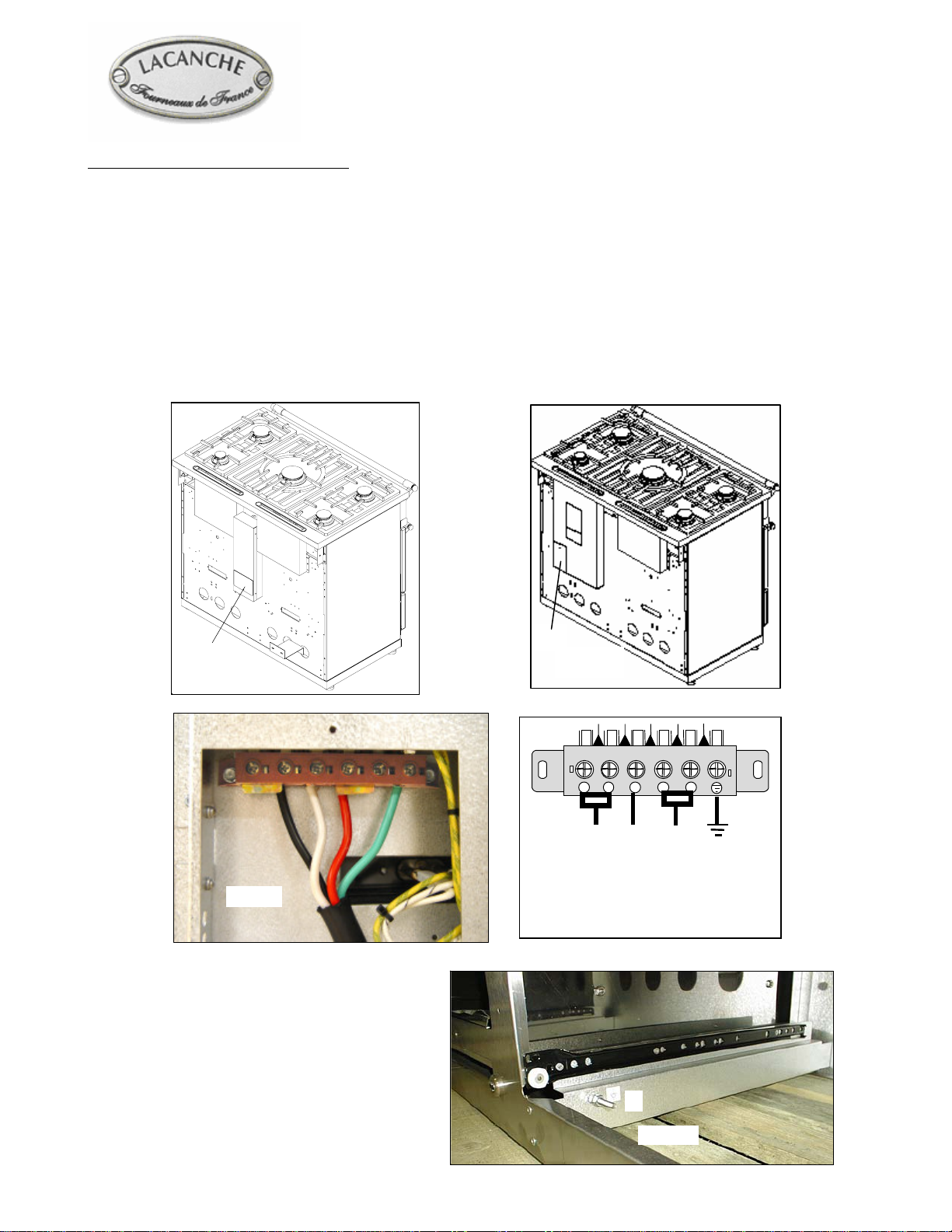
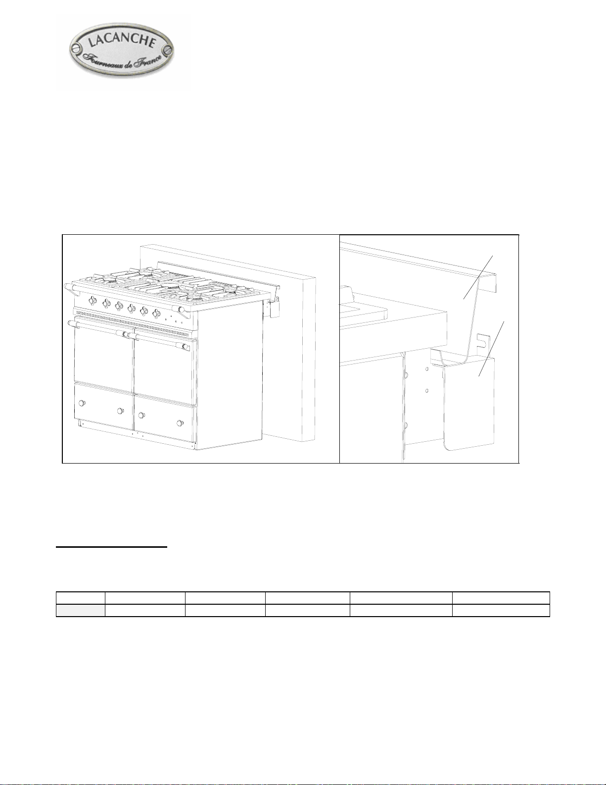
Gas connection :
1/2” ID NPT (Sch 40) inlet, on male coupling (Ein Figure 12). Sealant
on all pipe joints must be resistive to LP gas.
If used, a flex gas line for the gas supply must be metal of at least 1/2”
ID NPT approved by an approved certifying agency (A.G.A., C.G.A,.
etc.) in compliance with ANSI Z21.41 and Z21.69. Never use a hose
made of rubber or other synthetic material.
After connection :
Check the manifold pressure on pressure connection Ø 15/21, 1/8” NPT on F
(Figure 13).
The appliance is designed to operate with the gas pressures in Table 3.
Table 3
Country GAS Pressure (Pn)
U.S. Natural gas 6’’ WC
U.S. L.P. propane 10’’ WC
Fig. 12
E
Fig. 13
F