Lacanche CAFE MODERNE Manual

Contents:
1 Introduction
2 Important Information
3 Extraction Performance
4 Installation
5 Operating Instructions
6 Maintenance
7 Specifications
9
General Arrangement Drawings
Remote Motor Wiring Illustrations
1. INTRODUCTION
Your range cooker is a semi-professional unit which gives you
the power and flexibility to realise your full potential in the
kitchen. Inevitably, during the cooking process, there will be
heat, vapours and fumes produced. Your FM extractor has
been designed to complement the range cooker both in looks
and performance in order to create the ideal environment for
creative cooking.
2. IMPORTANT INFORMATION
The exhaust air must not be discharged into a flue which is
used for exhausting fumes from appliances supplied with
energy other than electricity e.g. oil or gas-fired central heating
boilers, gas-fired water heaters, etc.
Requirements of the relevant authorities concerning the
discharge of exhaust air must be complied with.
Pay particular attention to fire risk when frying. To minimise
the risk of fire, all instructions relating to cleaning the grease
filters and removing grease deposits must be adhered to.
Do not flambé under the extractor.
The minimum clearance between the top o the hob or
cooker and the bottom o the extractor should be within
the ollowing range (unless a greater distance is specified by
your cooking appliance or furniture manufacturer):
• hob-to-extractor minimum clearance distances:
750mm minimum above Lacanche hobs and cookers
• hob-to-extractor clearance recommended: 800-850mm
• Minimum ceiling height with standard chimney: 2242mm
The minimum distance between the hob and the bottom of the
extractor is essential for safety reasons and to prevent
overheating of the extractor and its components.
The maximum distance between the hob and the bottom of
the extractor is required to ensure that the extractor collects
the cooking fumes and odours efficiently.
Please also note that a 90
o
bend in 150mm flexible ducting will
require 215mm minimum headroom to give a smooth radius
with no kinking.
You are advised to install measures designed to reduce
the incidence o cold draughts entering the property via
any ductwork.
• For extractors with internal or inline motors this should, at
the very least, consist of an external duct termination
with integrated non-return flaps (e.g. gravity shutter wall
grille/louvre) and/or an inline backdraught shutter.
•
For wall-mounted motors an inline backdraught shutter is
recommended.
3. EXTRACTION PERFORMANCE
The primary influence on the overall performance of the
extractor is the design of the ducting which takes the exhaust
air from the extractor to the outside. The duct route should be
a prime consideration during the initial stages of the kitchen
design (We do not recommend recirculating air back into the
kitchen).
Please note the ollowing:
• Easy access to the duct route during installation is
important. Lack of access may require the “blind” fitting of
flexible ducting, with increased risk of unseen kinks and
impaired efficiency.
• The extractor is provided with a spigot suitable for
connecting 150mm diameter ducting.
• Note: the cross-sectional area of 150mm diameter ducting
is the minimum area consistent with efficient extraction.
Reducing the duct size seriously reduces performance.
• The most efficient configuration is to duct straight through
an outside wall so try to position the cooker against an
outside wall when designing your kitchen.
• Well installed, correctly sized rigid round ducting, or an
equivalent flat channel system will usually perform best,
with round semi-rigid (like flue liner) being a very good
alternative. Flexible (foil or plastic film) ducting is
economical but its use should be minimised as it gives the
worst performance and should only be used for very short
duct runs or initial connection and should be pulled taut to
prevent significant losses in extraction efficiency.
Installation, Operation
and
Maintenance
Instructions
CAFÉ MODERNE
Range Hoods
FMOD 900 1800
WARNING
Proper care must be taken to ensure that the negative
pressures caused by high performance extraction
systems do not adversely affect the safe operation of
certain types of fuel-burning appliances (gas, oil or solid
fuel), including those installed in the kitchen and
possibly also those installed in other parts of the house.
Where such fuel-burning appliances are installed,
adequate ventilation MUST be provided in the room of
installation, located and sized such that the negative
pressure in the room created by the extractor does not
exceed 4Pa.
In case of doubt, do not operate the extractor and fuel-
burning appliance(s) simultaneously and consult an
appropriate (for the fuel type) expert for advice.
ELECTRICAL SAFETY
This appliance requires an earth connection.
Ensure that the supply voltage corresponds to that
marked on the rating label inside the extractor.
The extractor must be isolated from the electrical supply
before carrying out any cleaning or maintenance
operations.

Ca é
M
oderne
Range Hoods
Installation, Operating & Maintenance Instructions
W1512 FMOD Moderne Range ood O&M Dec 16.docx
Page 2 Fornair
• A route with more than two 90° bends will significantly
degrade the performance of the extraction system. If
possible, avoid having a 90° bend at the extractor exhaust
spigot; keep bend radii as large as possible to maintain a
smooth airflow without vortices; avoid kinks in flexible
ducting; pull flexible ducting taut over straight runs to
ensure that the internal surface is as smooth as possible.
• Duct runs in excess of 5 metres are not recommended and
will seriously impair efficiency - if you are concerned then
please call for advice.
• The hood can be vented either to the top exhaust or the
rear exhaust position. Use the position which gives the
shortest duct route length and least number of bends. (The
blower will need to be rotated for ducting directly through
the rear exhaust position.)
4. INSTALLATION
Do not throw away the box and any internal packaging
until installation is ully completed - the packaging may be
required in the unlikely event that hood must be returned.
4.1. Remove the Grease Filters
Place extractor on its back plate on a horizontal surface.
To remove the grease filters pull/lift the filter release lever
away from the hood base. This releases the retaining clips
allowing the filter to be carefully lifted away from the hood.
Take care not to scratch the hood.
The internal fixing holes, blower assembly and/or spigot
blanking plate can now be accessed through the opening in
the baseplate.
4.2. Exhaust Position
The hood can be vented either to the top exhaust or the rear
exhaust position. Each exhaust position has 4 fixing points
onto which can be attached either the blower/spigot assembly
or a blanking plate.
Position the blower/spigot assembly in the chosen exhaust
position and the blanking plate in the unused position, using
the original fixings and washers supplied.
When changing the exhaust position, care should be taken not
to excessively pull or twist the cable attached to the blower.
4.3. Duct Installation
Make holes, as necessary, in the walls or ceiling to take the
ducting from the exhaust spigot location to the outside. *
Note: A 175mm diameter hole is suitable for both ducting and
any electrical cables (such as power or remote motor cables)
to pass through.
The duct route length should be kept as short as possible with
as few bends as possible (see Section 3).
If terminating on an outside wall a suitable weather louvre
should be fitted - an airbrick must never be used.
*I you have purchased a bespoke model with two exhaust
spigots itted then two individual 150mm ducts should be
run.
• Recirculating Models
We do not recommend recirculating air installations and they
should be avoided wherever possible (see section 3).
If your extractor has been adapted for recirculation (not our
standard configuration) then adequate provision must be
made for the exhausted air to return into the kitchen
(equivalent to 150mm round duct) - e.g. Purchase of a special
chimney with vents, ducting to a vent in the room, or finishing
the chimney short of the ceiling. Failure to do so may cause
the unit to overheat and fail and will invalidate your warranty.
4.4. Remote Motors
If your extractor has been purchased to operate with a
standard inline or external remote motor (SEM) then you will
find a black plastic box outside the extractor (on flying leads)
containing electrical terminals for connection to the remote
motor cable assembly. This box is referred to as the remote
motor terminal box.
Each terminal inside the remote motor terminal box has one
side connected to a coloured wire, which leads back to the
hood control system. The remote motor cable assembly also
has coloured wires and these are connected to the empty
terminals such corresponding colours are opposite and
connect to each other; i.e. red connects to red, blue to blue,
and so on...
Not all terminals will be used because each remote motor type
is configured differently.
An electrician or Part P registered electrical installer should
undertake any work associated with the electrical installation
of SEM remote motors.
Please refer to Section 9, Remote Motor Wiring
Illustrations, for more information.
If you need to extend the remote motor cable then additional
cable can be purchased. Alternatively, it may be extended
using 7 core x 0.5mm flex. It is vital to ensure that any new
cable is inserted such that the core colour integrity is
maintained; i.e. a core that started as red must terminate as
red, blue as blue, purple as purple, and so on.
Any remote motor should be installed in accordance with the
installation instructions that accompany it. It must be installed
in an easily accessible location for future maintenance. We
are not responsible for providing the means of access (e.g.
scaffolding or any alterations to the building and/or furniture
necessary to make access possible) in the event of any
maintenance requirement.
No separate power supply is required for S M remote
motors.
4.5. Fixing the Hood to the Wall
If you are fitting a splashback it is usually best to install it
before the hood.
Important:
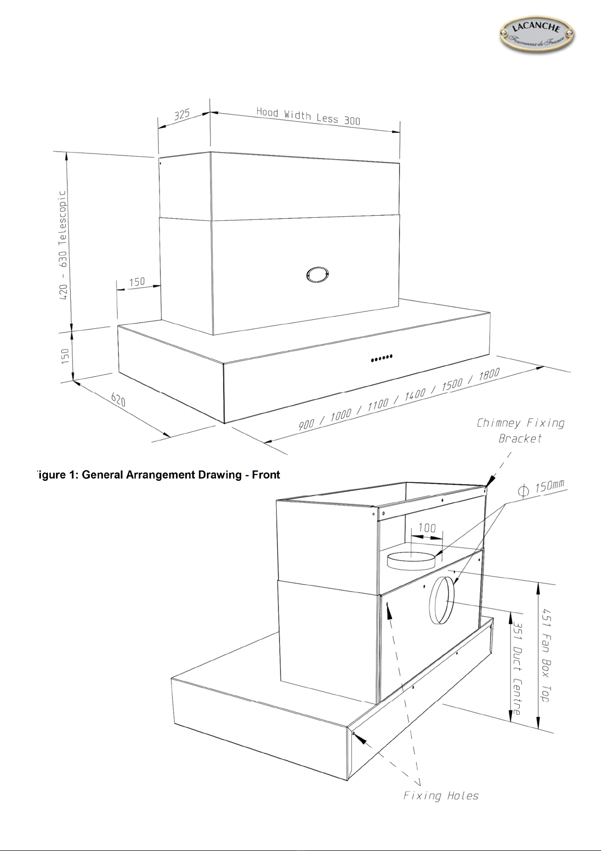
• Line drawings re erenced in this section can be ound
in Section 8: General Arrangement Drawings.
• The chimney can be removed to ease handling of the hood
and to provide access to the top outlet duct spigot.
• The supporting wall must be of good quality, have an even
surface and be sturdy enough to support the extractor.
• Fixings must be used which are suitable for the type of wall
construction.
• Fixing the hood to the wall requires a minimum o 2
people.
• No wall fixings are provided.

Ca é
M
oderne
Range Hoods
Installation, Operating & Maintenance Instructions
W1512 FMOD Moderne Range ood O&M Dec 16.docx
Page 3 Fornair
Method
Mark a horizontal line on the wall where the bottom edge of
the hood needs to be - if you have already fitted a splashback
then the top edge of this will serve.
Mark a vertical centre line, up to the desired chimney height,
to help you to accurately position the hood and chimney
bracket later.
Remove the grease filters to gain access the internal fixing
holes.
Mark the positions of the hood fixing hole centres and prepare
the wall to accept your chosen fixings, see Figure 2 “Layout of
ood Rear”.
Tip. The easiest way to mark fixing hole positions on the wall
is to offer up the hood in the desired position and then mark
the wall through the fixing holes in the hood rear (working
through the filter openings). This is a 2-person job.
Mark and prepare hole(s) suitable to accommodate 150mm
diameter ducting. A 175mm diameter hole is recommended to
provide some alignment tolerance and allow clearance for any
clips used to secure the duct or cables passing through to
remote motors. If using the rear exhaust spigot position then
accuracy is critical, see Figure 2.
Secure the hood, using fixings suitable for the wall
construction, in the previously marked positions
Tip. To use the rear exhaust spigot position you may have to
connect the ducting prior to fixing the hood to the wall - rigid
ducting is strongly recommended.
Unscrew the chimney bracket from the inner telescopic
chimney section and mark the positions of the chimney fixing
bracket holes on your wall.
lease note: The bracket finishes flush with the finished top
of the chimney and the central hole can be used to view your
centre line.
Tip. The easiest way to mark fixing hole positions on the wall
is to offer the bracket up into the desired position and then
mark the wall through the fixing holes in the bracket rear.
Secure the chimney bracket, using fixings suitable for the wall
construction, in the previously marked positions.
Connect the ducting and electrical supply cord as described in
section 4.6 and 4.7.
Slide the inner chimney up and over the bracket and secure it
in position using the screws previously removed.
4.6. Electrical Supply
The extractor is a stationary appliance designed to be
connected by fixed wiring to the electrical supply. A competent
Part P registered electrical technician must perform the
electrical installation.
The hood must be fed from a 230Vac single phase electrical
supply using a switched spur fitted with a 3A fuse. The spur
should be located adjacent to the hood/cooker so that the
supply can be disconnected from the hood using the switch.
The means of disconnection from the supply must have a
minimum contact separation of 3mm in all poles. Alternatively,
a means of disconnection in the fixed wiring according to the
relevant wiring rules must be fitted.
The appliance is supplied with an electrical supply flex for
connection to the electrical supply. The mains supply is
connected to the free end of this flex as follows:
INCOMING SUPPLY CORD CONNECTIONS
Core
Core Colour
Live Brown
Neutral Blue
Protective Earth Green/Yellow
4.7. Connecting the Ducting
Whether you start running ducting at the hood end or at the
termination point (where it exits the building) will depend upon
your site conditions. There is no right or wrong order,
providing that ducting is installed so that it is as smooth as
possible and can be disconnected should the need arise for
maintenance.
Terminate the ducting where it exits the building. If using a
wall mounted weather louvre, secure the ducting to the louvre
spigot and attach the louvre to the wall. Ensure that the air fins
are directed downwards. If you are fitting an alternative
termination, ensure that the ducting is secure.
If using expanding foam, make sure that any flexible ducting is
supported internally to prevent it crushing where foamed.
Pull flexible ducting back along its route such that it is as
smooth as possible.
Connect ducting to extractor exhaust spigot using plastic tie
straps or a suitable alternative (e.g. jubilee clip) - do not use
duct tape as the sole means of connection. For rear exit
exhaust positions the duct should be attached prior to fixing
the extractor to the wall.
When the extractor is in position, check that the duct has not
been flattened or kinked along its route.
Note: Internal motor models have non-return flaps as part of
the spigot assembly to reduce air blowing back into the unit
from outside.
Take care not to obstruct the backdraught flaps when
connecting ducting, making sure that the ducting is not
preventing the flaps from opening properly. This is most
commonly a problem that can be encountered when flexible
ducting is used and we recommend semi-rigid ducting is used
instead. Overtightening of jubilee clips close to the base of the
spigot can also prevent the flaps from opening properly. If you
have installed non-return flaps elsewhere and draughts are
unlikely to cause a problem, then these flaps are easily
removed.
ELECTRICAL HAZARD
DISCONNECT ELECTRICAL SUPPLY
BEFORE PROCEEDING FURTHER

Ca é
M
oderne
Range Hoods
Installation, Operating & Maintenance Instructions
W1512 FMOD Moderne Range ood O&M Dec 16.docx
Page 4 Fornair
5. OPERATING INSTRUCTIONS
Switch on the power at the fused spur.
Your extractor has 6 pushbuttons which illuminate when
pressed.
6. MAINTENANCE
Regular maintenance is essential to ensure good performance
and long-life.
To maintain the immaculate appearance of the extractor, and
to minimise fire risk, ensure that grease deposits on the
extractor surfaces are kept to a minimum by regular cleaning.
To clean the stainless steel surfaces of the extractor, use a
soft cloth and a suitable cleaning agent, such as a specially
produced stainless steel cleaner or washing up detergent and
warm water.
Painted surfaces should be cleaned using a soft cloth,
detergent and warm water.
Glass surfaces should be cleaned with a suitable glass
cleaning agent.
• Do not use abrasive cleaning materials or products.
• Do not use bleach based cleaning materials or
products.
Clean the grease filters in a dishwasher or by hand-washing in
hot water and detergent every 2 months - sooner if the
extractor is used extensively and filters become grease laden.
• Whilst you can expect years of service from mesh grease
filters, they are considered a consumable item and may
deteriorate over time and need replacement, particularly
when cleaned in a dishwasher. For dishwasher users
adhering to a 2-monthly cleaning interval we recommend
grease filter replacement every 5 years to maintain
optimum performance, even if they show no visible signs
of deterioration. For all users, filters should be replaced
whenever they exhibit signs of physical wear.
6.1. Removing the Grease Filters
The clip in grease filters have an integrated sprung latch
mechanism.
Release the latch by pulling the lever and remove the filter.
Filters are replaced by locating the fixed tabs opposite the
lever catch into corresponding slots in the extractor base and
then pushing the filter into position with the latch held open.
Once the filter is in position release the lever, allowing the
latch to engage.
6.2. Replacing Lamps
The lamps are long life LED units and are not designed for
end user replacement. In the unlikely event of failure please
call for assistance.
7.
SPECIFICATIONS
All Models
Supply Voltage: 230V~ 50 z
Lighting: 12V 2.6W LED (Per Lamp): 12V, 2.6W
See general arrangement drawings for lamp
quantity installed in your model.
er lamp
Extractor Duct Spigot Diameter: 150mm
Total power:
See rating plate
Internal Motor Speci ications
Airflow, nominal in free air: 800 m
3
/hr
Power input: 275W
Duct Spigot diameter: 150mm
SEM1
EL
Inline Duct Motor Speci ications
Airflow, nominal in free air: 800 m3/hr
Power input: 275W
Duct Spigot diameter: 150mm
SEM2
EL
Wall Mounted Motor Speci ications
Airflow, nominal in free air: 1,000 m
3
/hr
Power input: 200W
Duct Spigot diameter: 150mm
SEM7
EL
Wall Mounted Motor speci ications
Airflow, nominal in free air: 200mm Dia Duct 1,700 m
3
/hr
Airflow, in free air via supplied 150mm reducer 1,500 m
3
/hr
Power input: 490W
Duct Spigot diameter: 200/150mm
SEM8
EL
Inline
Motor speci ications
Airflow, nominal in free air: 200mm Dia Duct 1,300 m
3
/hr
Airflow, in free air via supplied 150mm reducer 1,100 m
3
/hr
Power input: 250W
Duct Spigot diameter: 200/150mm
Recommended Protective Fuse Sizes or Electrical Supply
Models installed with:
Internal Motor
Remote Motors
3A
CAUTION
To minimise the risk of fire, all instructions relating
to cleaning the grease filters and removing grease
deposits must be adhered to.
Pushbutton Functions
The extractor controller automatically switches o
the appliance i there has been no operator action
or 4 hours.
After 30 hours accumulated running GREASE
FILTER CLEANING will be signalled by all 6
indicators flashing. Reset by pressing Push-button
FAN OFF (delay).
Lights ON/OFF
Motor ON - SPEED 1
Motor OFF
Motor ON – TIMED INTENSIVE MODE
(Reverts automatically to speed
3
after 5 minutes
)
Motor ON - SPEED 3
Maximum Speed for Normal Use
Motor ON - SPEED 2
Motor RUN ON TIMER
(OFF after 10 minutes to clear fumes)
For more detailed specification and energy
efficiency information please refer to the
product fiche for your product

Ca é
M
oderne
Range Hoods
Installation, Operating & Maintenance Instructions
W1512 FMOD Moderne Range ood O&M Dec 16.docx
Page 5 Fornair
Figure 1: General Arrangement Drawing - Front
Figure 2: General Arrangement Drawing - Rear
8.
GENERAL ARRANGEMENT DRAWINGS

Ca é
M
oderne
Range Hoods
Installation, Operating & Maintenance Instructions
W1512 FMOD Moderne Range ood O&M Dec 16.docx
Page 6 Fornair
Figure 3: Hood Layout Explained
Figure 4: Hood Baseplate Layouts

Ca é
M
oderne
Range Hoods
Installation, Operating & Maintenance Instructions
W1512 FMOD Moderne Range ood O&M Dec 16.docx
Page 7 Fornair
9.
SEM REMOTE MOTOR WIRING ILLUSTRATIONS
Remote Motor
Terminal Box
Fig. 1 Open Terminal Box
Empty Terminal for
Motor
Connections
Extractor
Fig. 2 Typical System (SEM2 Shown)
Red
Blue
White
Grey
Black
Green/Yellow
Brown
Orange
Yellow
Purple
Fig. 4 SEM 1 / SEM 2
Electrical Connections
Fig. 5 SEM 7 / SEM 8
Electrical Connections
Fig. 3 Terminal Colour Positions
Remote Motor
Cable Assembly
(Orange/Yellow link
wire
is
included
)
Remote Motor
Cable Assembly
(Orange/Purple link
wire
is
included
)

Café Moderne Range Hoods
Installation, Operating & Maintenance Instructions
W1512 FMOD Moderne Range ood O&M Dec 16.docx
Page 8 Fornair
Fourneaux de France Ltd
Unit 3 Albion Close, Newtown
Business Park,
Poole Dorset, BH12 3LL
el: 01202 – 733011
Email: [email protected].uk
www.fdef.co.uk
Table of contents
Other Lacanche Ventilation Hood manuals
Popular Ventilation Hood manuals by other brands

GE
GE ZVB30ST4SS installation instructions

Bosch
Bosch DWA091450 operating instructions

Electrolux
Electrolux EI36DD10KS Product specifications

Whirlpool
Whirlpool GXW7230DAS Installation Instructions and Use & Care Guide

ELICA
ELICA ETR836SS Use, care and installation guide

Maytag
Maytag UXW7230BSS Installation Instructions and Use & Care Guide

CIARRA
CIARRA CBCS6906D Installation and user manual

Fulgor Milano
Fulgor Milano URBANTECH 90 Instructions for installation and use

DeDietrich
DeDietrich DHL7173X Guide to installation

FALMEC
FALMEC Vega Instruction booklet

GE
GE JV535 Owner's manual and installation instructions

Imperial
Imperial WH1900 Installation instructions & warranty information