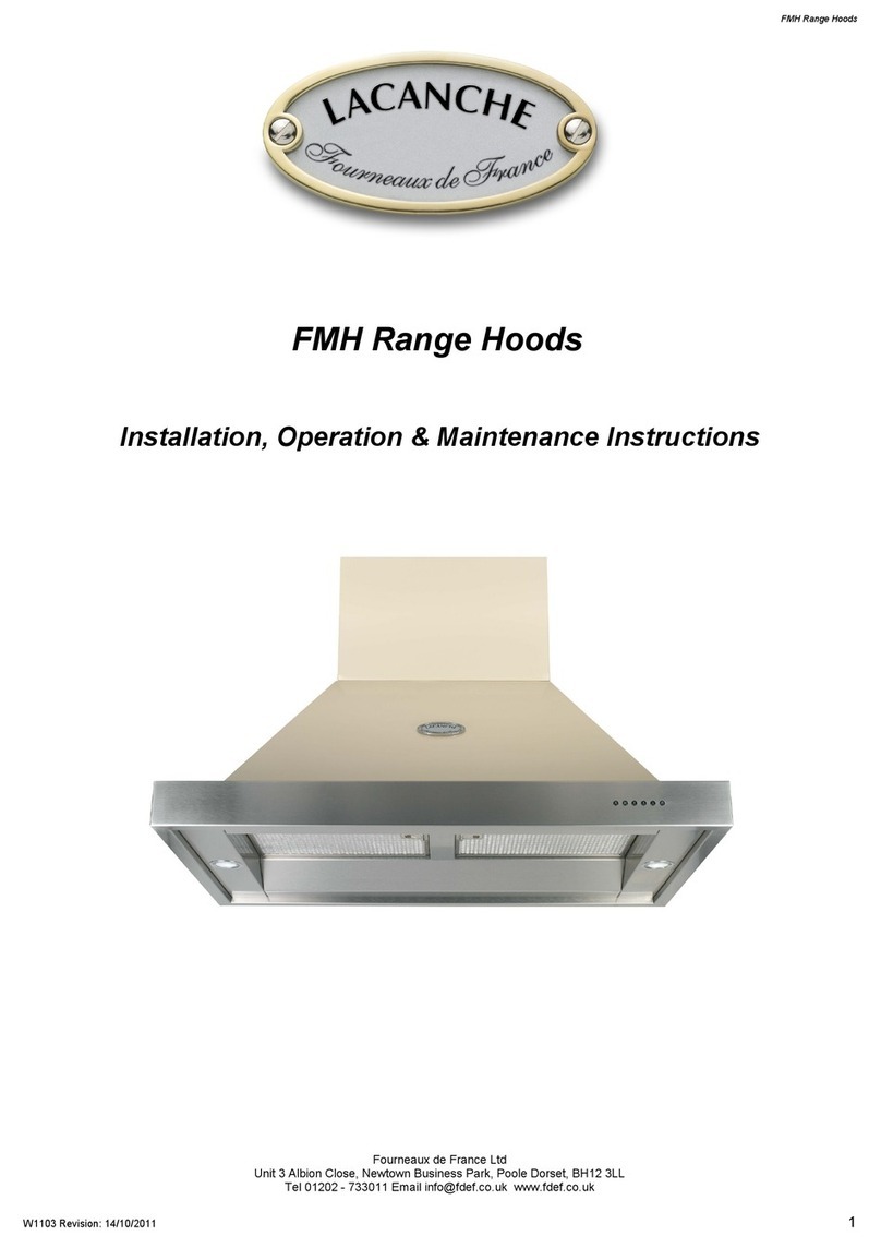
Lacanche FCE Range Operation instructions

Use and maintenance instructions for
FCE Range
High Performance extraction systems.

1
INDEX PAGE
SECTION 1 CHECKLIST OF ITEMS 2
SECTION 2 EXTRACTION PERFORMANCE 2
SEECTION 3 IMPORTANT INFORMATION 3
SECTION 4 INSTALLATION 4-8
SECTION 5. ELECTRICAL INSTALLATION 9
SECTION 6. OPERATING INSTRUCTIONS 10
SECTION 7. MANTENANCE 11-12
SECTION 8. TECHNICAL SPECIFICATIONS 13

2
SECTION 1. CHECKLIST OF ITEMS
Check that the following items have been supplied:
1 extractor hood (Complete with blower motor, lighting, mains supply cord and
grease filter(s)
SECTION 2. EXTRACTION PERFORMANCE
The most important influence on the performance of the extractor is the design of the
ducting which takes the exhaust air from the extractor to the outside. The duct route
should be a prime consideration during the initial stages of the kitchen design. Please
note the following:
The extractor is provided with a spigot(s) suitable for connecting 150mm diameter
duct.
Note: 150mm is the minimum duct diameter consistent with efficient extraction.
Double blower (fan) models will require two independent duct runs.
The exhaust duct route length should be kept as short as possible with as few
bends as possible.
The most efficient configuration is to duct straight through an outside wall so try to
position the cooker against an outside wall when designing your kitchen layout.
The hood can be vented either to the top exhaust or the rear exhaust position. Use
the position which gives the shortest duct route length and least number of bends.
A route with more than two 90 degree bends will significantly degrade the
performance of the extraction system. Keep bend radius as large as possible to
maintain a smooth airflow without vortices; avoid kinks in flexible ducting; pull
flexible ducting taut over straight runs to ensure that the internal surface is as
smooth as possible.
Rigid 150mm diameter (or equivalent rectangular) ducting should be considered for
long or complex duct runs (which must be sourced separately).
DO NOT REDUCE THE DUCTING DIAMETER OF 150MM AS THIS WILL
REDUCE THE EXTRACTORS PERFORMANCE

3
SECTION 3. IMPORTANT INFORMATION
The following minimum headroom is required to accommodate the cooker and
hood:
Cooker height (nominal):
900mm
Min Cooker-to-hood clearance
Clearance with FdeF backsplash
800mm
850mm
Hood height:
450mm
Advice only: Clearance between
hood and ceiling:
5mm
(recomme
nded)
Required ceiling height (min):
Rear Exit Spec
2155mm
The minimum distance between the range hob burners and the bottom of the
extractor is essential to prevent overheating of the extractor and its components.
If you are fitting a Fourneaux backsplash then the cooker-to-hood clearance is
dictated by the backsplash height of 850mm excluding flanges
Please also note that a 90 degree bend in the flexible ducting will require 315mm
minimum headroom to give a smooth radius with no kinking.
The exhaust air must not be discharged into a flue which is used for exhausting
fumes from appliances supplied with energy other than electricity, e.g. oil or gas-
fired central heating boilers, gas-fired water heaters, etc.
Requirements of the relevant authorities concerning the discharge of exhaust air
must be complied with.
Adequate ventilation of the room must be provided when the cooker extractor and
appliances supplied with energy other than electricity (e.g. gas-fired or oil-fired
heaters, etc.) are used simultaneously. The room must be provided with vents to
allow a constant flow of fresh air.
Attention: This appliance requires an earth connection
Ensure that the supply voltage corresponds to that marked on the rating label
inside the extractor.
The extractor must be isolated from the electrical supply before carrying out any
cleaning or maintenance operations.
If the power supply cable is damaged, it must be replaced by the manufacturer,
its after-sales service, or a suitably qualified person.
Pay particular attention to fire risk when frying. To minimise the risk of fire, all
instructions relating to cleaning the grease filters and removing grease deposits
must be adhered to
Do not flambé under the extractor
The hood has been designed to remove the kitchen smells; any other additional
use shall be regarded as non-intended.
This appliance is not intended for use by person (including children) with reduced
physical, sensory, metal capabilities, or lack of experience and knowledge, unless
they have been given supervision or instruction concerning use of the appliance
by a person responsible for their safety.
This appliance is for domestic use only.

4
SECTION 4. INSTALLATION
Removing the Grease Filter(s)
Place extractor on its backplate on a horizontal surface.
The grease filter(s) have an integrated sprung latch and release mechanism.
Release the latch by pulling the lever and remove the filter. The filter is replaced
by locating the fixed tabs on the filter into corresponding 2mm slots in the
baseplate and then pushing the filter into position with the latch held open. Once
the filter is in position carefully release the lever, allowing the latch to engage in
corresponding 5mm slots.
Reversing Motor Outlets
Your Fornair extraction hood can be vented either to the top or rear exhaust
position.
Remove grease filters please figure XX
With the power isolated to the hood disconect the motors as per Fig1
Fig 1

5
With the motor(s) disconnected remove the three fixing screws holding the motor
plate to the back panel of the hood. See Fig 2
Fixing screws motor plate rear of the hood
Fig 2
With the motor(s) disconnected remove the three fixing screws holding the motor
plate to the top panel of the hood. See Fig 3
Fixing screws motor plate top of the hood
Fig 3

6
With all the fixings screws and the motors disconnected remove the motor plate
from the hood and reverse the position of the motor(s). See Fig 4
Fig 4
Duct Installation
Make a hole or holes in the walls and/or ceiling, as necessary, in order to take
150mm diameter ducting from the extractor spigot(s) to the outside.
The exhaust duct route length should be kept as short as possible with as few
bends as possible.
If using FdF duct kit ensure that holes in external wall will accommodate the
ducting and connecting strap (Min 160mm diameter).
Warning
Do not reduce the ducting diameter from 150mm as this will affect the
performance of the hood and could damage the motor. Damage caused
to the hood by incorrect ducting will not be covered by warranty.

7
FCE1000

8
Fixing the Hood to the Wall
If you are fitting a Fourneaux backsplash it must be fitted before the hood.
The supporting wall must be of good quality, have an even surface and be sturdy
enough to support the extractor.
Fixings must be used which are suitable for the type of wall construction.
Your Lacanche hood has four fixing holes and two suspending Brackets.
Offer the hood into position and insure that the hood is level.
Mark the fixing holes and suspending brackets.
Using a suitable size drill for you fixings. Drill and secure the wall fixings.
With all the holes drilled and with the fixing plugs in place mount the suspending
brackets
Hang the extractor onto the suspending brackets
Ensuring that the hood is level secure the hood with the remaining fixing screws
If the hood is to be vented from the rear connect the ducting to the ducting spigot
on the hood.
Connecting the Ducting
Connect ducting to extractor exhaust spigot(s). This may have to be done prior to
fixing the extractor to the wall.
When the extractor is in position, check that the duct has not been flattened or
kinked along its route.
Connect the ducting to the wall louvre spigot or alternative outside termination.
Secure the louvre to the outside wall. Ensure that the air fins are directed
downwards.
Refit the grease filter(s).
For reference see figure 6 & 7
Fig 6 Connecting Ducting to ducting spigot.

9
Fig 7 Connecting Ducting spigot to hood

10
Section 5. Electrical Installation
ELECTRICAL HAZARD
DISCONNECT ELECTRICAL SUPPLY
BEFORE PROCEEDING FURTHER
The extractor is a stationary appliance designed to be connected by fixed wiring to
the electrical supply. A competent electrical technician must perform the electrical
installation.
The hood must be fed from a 230Vac single phase electrical supply using a
switched spur fitted with a 3A fuse for single blower models or a 5A fuse for
double blower models . The spur should be located adjacent to the hood/cooker so
that the supply can be disconnected from the hood using the switch. The means of
disconnection from the supply must have a minimum contact separation of 3mm
in all poles. Alternatively, a means of disconnection in the fixed wiring according
to the relevant wiring rules must be fitted.
A supply cord for connecting the spur to the extractor is included.
The mains supply is connected to the free end of this cord as follows:
INCOMING SUPPLY CORD CONNECTIONS
Core
Core Colour
Live
Brown
Neutral
Blue
Protective Earth
Green/Yellow
Warning
Proper care must be taken to ensure that the negative pressures caused by high
performance extraction systems do not adversely affect the safe operation of
certain types of fuel-burning appliances (gas, oil or solid fuel), including those
installed in the kitchen and possibly also those installed in other parts of the
house.
Where such fuel-burning appliances are installed, adequate ventilation MUST be
provided in the room of installation, located and sized such that the negative
pressure in the room created by the extractor does not exceed 4Pa.
In case of doubt, do not operate the extractor and fuel-burning appliance(s)
simultaneously and consult an appropriate (for the fuel type) expert for advice.
Should you require any further technical information please do
not hesitate to call Fourneaux de France Ltd on:
01202 733011

11
Section 6. Operating Instructions
Switch power on at the fused spur.
The extractor has 5 push-buttons which illuminate when
selected
TL to switch on/off lights
T1 to switch on motor at the first speed
T2 second speed
T3 third speed
T4 fouth speed (intensive will remain on for 5minutes)
To turn the motor off press T1
Auto Switch-Off
To activate the auto switch-off function, switch on the cooker hood at the desired speed
and immediately after press “T1” button for some seconds till all LED lights start Flashing.
Pressing one of the buttons (T1, T2, T3, T4) the auto switch-off can be programmed. Time
will be different according to the button which is pressed (T1=5 minutes, T2=10 minutes,
T3=15 minutes, T4=20 minutes). If the time of the switching-off is the same as the speed
previously set, the LED light Flashes. If the choice is different the LED of the speed
remains fixed.
IN CASE THE INTENSIVE IS CHOSEN, AFTER 5 MINUTES THE COOKER HOOD
AUTOMATICALLY PASSED TO 3^ SPEED AND THE AUTO SWITCH-OFF WILL BE AT THE 3^
SPEED.
Grease Filter Alarm
After 30 hours operating time of the cooker hood, at the moment of the switch-off, all the
LED lights will turn to fixed light for 30 seconds. This is to suggest the aluminium filters
require cleaning. To reset the alarm, press and hold T1+T4 buttons together. If this reset
operation is not carried-out, every time the cooker hood is switched-off the lights will
remain on for 30 seconds. This alarm will reoccur after each following 30 hours up to 120
hours operating time. At the end of the 120 hours operating time, at the moment of the
switch-off, all LED lights will start flashing for 30 seconds as a reminder that the aluminium
filter require cleaning or to rest the alarm. Once the alarm has been reset the procedure
starts again after 30 hours operating time of the cooker hood.

12
Section 7. Maintenance
WARNING
Unplug the appliance or switch off the circuit breaker before carrying out
maintenance operations.
Regular maintenance is essential to ensure good performance and long-life.
To clean the stainless steel surfaces of the hood use a damp cloth only. Do not
use abrasive cleaning materials or products on any surface.
Clean the grease filters in a dishwasher or by hand-washing in hot water and
detergent. Wash the filters at least once a month - sooner if the extractor is
used extensively
To maintain the immaculate appearance of the extractor, and to minimise fire risk,
ensure that grease deposits on the extractor surfaces are kept to a minimum by
regular cleaning.
METALLIC ANTI-GREASE FILTERS
The filters must be washed at least once a month with hot water and detergent.
Open by means of the handle (Fig.A/B).
Fig.B
Fig.A

13
LIGHTING
Using a small flat blade screw driver remove the lens cover
replace thE LED with one that has the same features (1.2W)
Do not use a higher rated lamp as this can cause damage to the electrical system
that will not be covered under warranty
Refit the lens cover by hand taking care not to break the glass.

14
SECTION 8. Technical Specifications
CONSTRUCTION CHARACTERISTICS
•STAINLESS STEEL SHEET BODY Thickness 8/10
•TELESCOPIC STACK IN VARIOUS DIMENSIONS
•ALUMINIUM BODY AISI 304 - 430.
GENERAL CHARACTERISTICS
•ELECTRICAL SYSTEM ACCORDING TO THE INTERNATIONAL REGULATIONS
•2 x 1.2W LED LIGHTS
•3 OPERATING SPEEDS (THE ELECTRONIC TYPE HAS 4 SPEEDS)
•COOKING COUNTER LIGHTING SYSTEM
•RAI ANTIJAMMING
•REFERENCE STANDARDS ACCORDING TO THE E.M.C. 89/336: EN55014,
EN60555-2 DIRECTIVES
•REFERENCE STANDARDS ACCORDING TO THE L.V.D. 73/23, WITH INT. 93/68:
•EN60335-1, EN60335-2-31 DIRECTIVES
•EFFICIENCY CLASS A
TECHNICAL DATA
FLOW RATE PER HOUR 920cbm/h
STATIC PRESSURE 550Pa
ABSORPTION 350W
SUPPLY VOLTAGE:
220-240V / 50-60HZ
WEIGHT KG 23

15
Table of contents
Other Lacanche Ventilation Hood manuals
Popular Ventilation Hood manuals by other brands

Gaggenau
Gaggenau AT 400-700 installation instructions

KRONAsteel
KRONAsteel PATRICIA 600 Application Sheet

Whirlpool
Whirlpool AH 50 CM X /HA Instructions for use

Whirlpool
Whirlpool HHBG 9.8 LTSI X Instructions for use

Monogram
Monogram ZV1050 installation instructions

Fujioh
Fujioh BUF-011 installation manual