(P/N)762.128RevBEN05/10•©copyright2009-2010 Kaba Mas LLC
page5
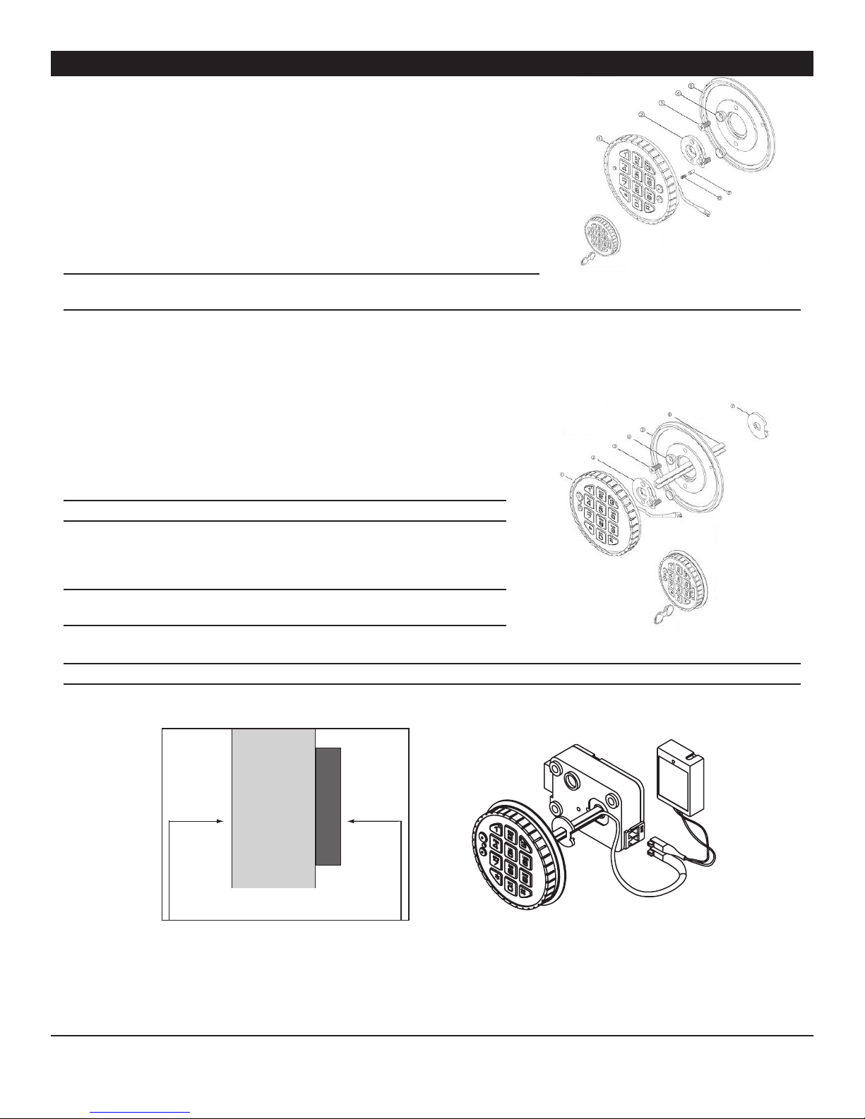
SWING BOLT
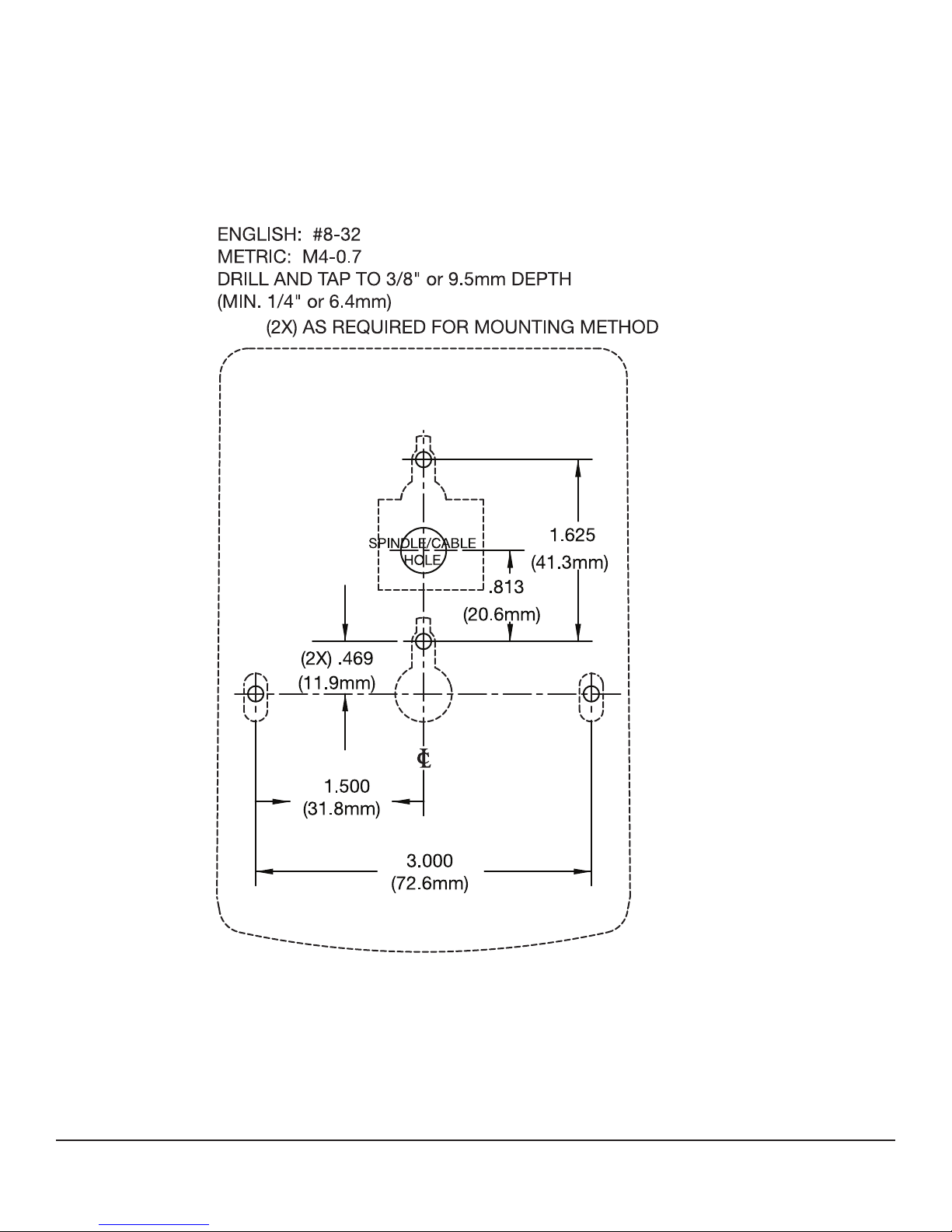
1.Mountthedialplate(p/n2676)centeredonthethroughhole.Attachthedialplate
withthetwomountingscrewsUS8-32(US)ortheM4-0.7(metric),andtheshoulder
bushings(p/n2618).
2.Slidethebearingplate(p/n2674)overcableandpressontothefastenersonthe
EntryDevice.
3.Feedthekeypadcablethroughthespindlecableholefromthefrontofthesafedoor.
4.Insertthesprings(p/n2893)andblockingpins(p/n2894)intotheholelocatedonthe
backofthekeypad.
5.Rotatethekeypadapprox.30°counter-clockwiseandplaceontothebushings.Then
turnthekeypadclockwiseuntiltheblockingpinclicks,andsecurestheEntryDevice
tothesafedoor.
WARNING: Once installed, the Entry Device cannot be removed from the safe door
without causing physical damage to the Entry Device.
6.Wheninstallingthelock,ensurethattheEntryDevicecableisrunningthroughthe
channelatthebackofthelock.
DEAD/SPRING BOLT
1.Mountthedialplate(p/n2676)centeredonthethroughhole.Attachthedial
platewiththetwomountingscrewsUS8-32(US)ortheM4-0.7(metric),and
theshoulderbushings(p/n2618).
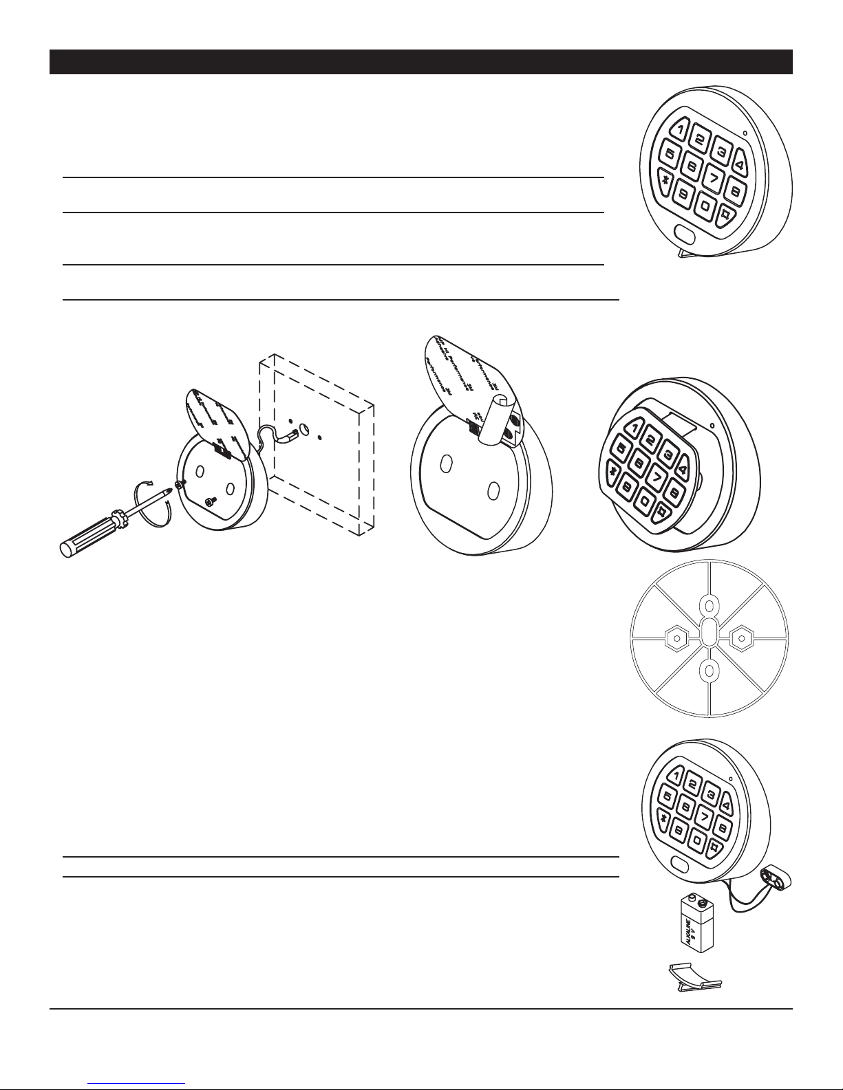
2.Measuretotalmountingthickness(doorthickness+mountingplate).(Figure3)
3.Cutthespindletoalengthof.700”(17mm)plusthetotalmountingthickness.
NOTE: the spindle must be deburred.
4.Insertthespindleintothekeypad,androutethecableinthegrooveof
thespindle.
5.Slidethebearingplate(p/n2674)overthecable,andpressontothefasteners
ontheEntryDevice.
NOTE: It is important to make sure the cable will not rub on the dial plate after
assembly.
6.FeedtheEntryDevice’scableandspindlethroughthespindle/cableholefrom
thefrontofthesafedoor.
WARNING: Spring and blocking pin are NOT installed when Entry Device is used with either the dead bolt or spring bolt locks.
7.Rotatethekeypadapprox.30°counter-clockwiseandplaceontothebushings.
8.Thenturnthekeypadclockwiseuntilthekeypadisvertical(Figure4).
9.Thespindleshouldprotrudebetween.300"-.350"(8-9mm)throughthesafedoor.
10. Slidethecableprotector(p/n2754)overthecableandspindle,untiltheatsiderestsagainsttheinsideofsafedoor.Routethe
cablethroughthegrooveofthecableprotector.
11. Gentlypullonthecabletoassurethatthereisnoexcesscableinthespindleholethatwouldrubonthemetaldoor.
12. Installthelockwiththeboltextendedontothespindle.
1.KeyPad
2.BearingPlate
3.MountingScrews
4.ShoulderBushing
5.DialPlate
6.Spring
7.BlockingPin
3035&3125EntryDevice
(SwingboltOption)
3125
1.KeyPad
2.BearingPlate
3.MountingScrews
4.ShoulderBushing
5.DialPlate
6.Spindle
7.CableProtector
3035&3125EntryDevice
(DeadBolt/SpringBoltOption)
3125
DOOR
MOUNTING PLATE
TotalMountingThickness=doorthickness
+mountingplate Cableprotector
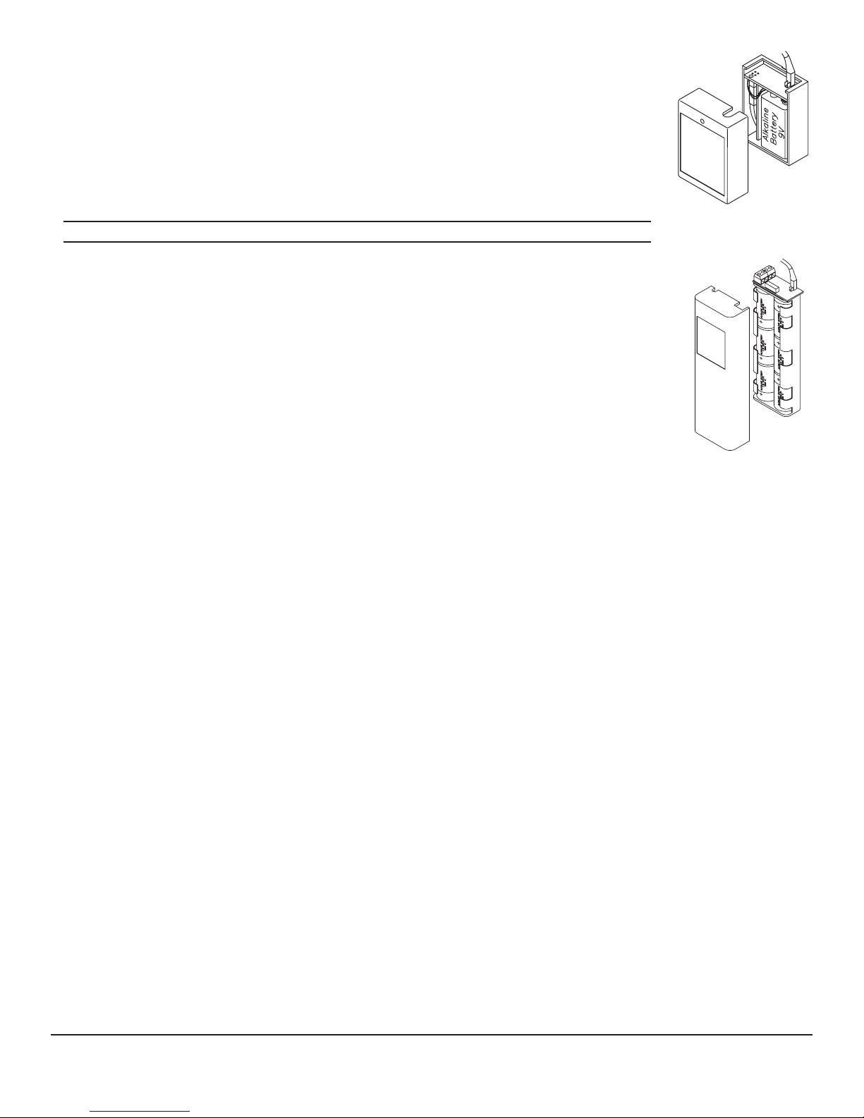
Batterycompartment
Figure3
Figure4
3035 & 3125 ROUND ENTRY DEVICE