Lailey abd Coates LC-07 User manual

Inverter Air Source Heat Pump
Split System
Lailey and Coates
Heat Pumps Engineered for British Homes
Product Installation Manual

2 Installation Manual 2014 - Riv 2
Inverter Air Source Heat Pump
Split System

3 Installation Manual 2014 - Riv 2
Contents
General Information..............................................................................................5
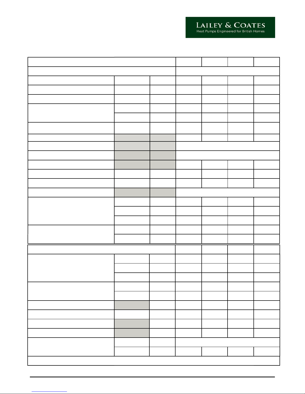
Technical Specification ..........................................................................................6
Installation of External Unit...................................................................................7
Installation of Internal Unit...................................................................................8
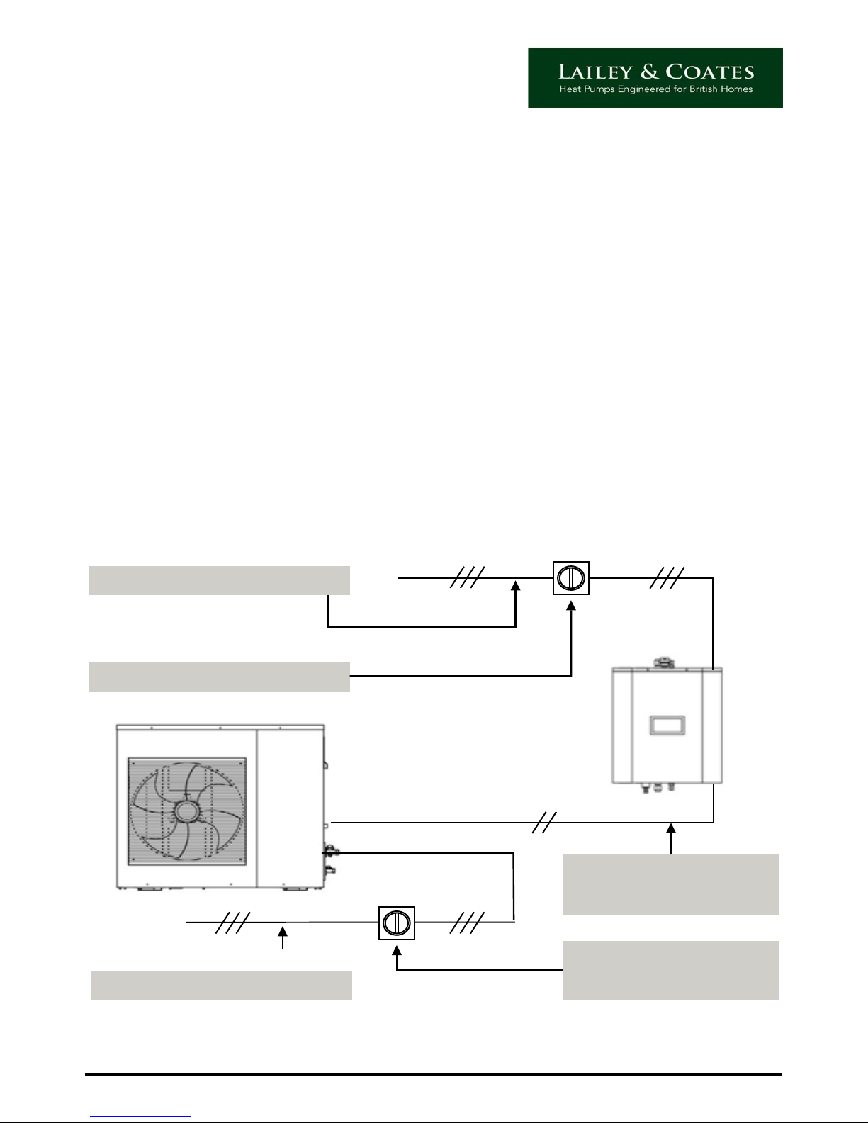
Wiring Instructions................................................................................................9
Rated power input and fuse information............................................................10
Indoor Electrical Connections..............................................................................11
Plumbing Installation...........................................................................................12
Refrigeration Installation.....................................................................................14
Dip Switch Settings..............................................................................................16
Pre-Operation Checklist.......................................................................................17
Commissioning ..................................................................................................18
LCD controller......................................................................................................19
How to set up LCD controller...............................................................................20
Setting the Hot Water Temperature....................................................................21
Setting the Heating Water Temperature..............................................................22
Setting the Heat Pump Timer..............................................................................23
Holiday Timer......................................................................................................26
Simple Trouble Shooting Guide.........................................................................27
Access to change system parameters..................................................................27
Fault / Error Codes...............................................................................................30
Commissioning Sheet..........................................................................................34

Installation Manual 2013 Riv 2 4
Thank you for purchasing a Lailey and Coates Air source Heat Pump.
Please read this manual carefully before installation and operation. It contains
important
information to enable a safe and successful installation. If you have any queries please
ring our Technical Helpline on 01753-537830 before running the Heat Pump.
Safety Instructions
To prevent injury/damage to persons or property the following instructions should be
followed at all times:
· This product should only be installed by Approved Lailey and Coates partners. All
installation engineers should be suitably qualified and made aware of the contents
of this manual.
· Repairs and Maintenance should be carried out by Approved Lailey and Coates
partners to ensure validity of Warranty.
· Internal and external units should be securely fixed to solid surfaces ensuring a
minimum support weight of 20g/mm2.
· All local regulations, by-laws and standards should be checked and adhered to at
all
times.
· Internal and External Units should be installed as per guidelines in this manual
ensuring adequate ventilation and airflow around the units.
· Care should be taken when cleaning/installing product so as to avoid water
ingress,
electric shock or damage to unit and associated pipework and cables. Both internal
and External units should be isolated for these purposes.
· This product has been designed for use by persons with experience of Heating
controls and as such should not be operated by children or persons with reduced
physical, sensorial or mental faculties unless supervised by a responsible person.

5 Installation Manual 2014 - Riv 2
General Information
The Lailey and Coates Split System consists of two major parts: The Internal and External
Units. They are connected via refrigeration pipes and an ELV, shielded, communication
Cable.
The external units can either be wall mounted or hard-standing but should be secured via
suitably designed mounting systems available from Lailey and Coates. When siting the
outdoor unit it is essential that an adequate, un-restricted level of airflow is available to
ensure correct operation and maximum efficiency of the system. See page 7.
The Internal Unit is designed to be wall mounted in a suitably dry position.
The Lailey and Coates Split System will accommodate all your heating and hot water
demands and is suitable for use with; under floor Heating, Radiators and Fan Coil Units.
The system is integrated with an Electrical Heater for extreme weather conditions and also
acts as a backup if there is a problem with the External Unit.
Model identification
LC - 15
Model Type
Lailey and Coates
Unit Size
Nominal Heating
Capacity
= 15 kW

Installation Manual 2013 Riv 2 6
Indoor unit LC-07 LC-10 LC-12 LC-15
Dimensions indoor unit
Height mm 549 549 609 609
Width mm 450 450 450 450
Depth mm 262 262 262 262
Weight
Gross Kg 35 36 39 40
Net Kg 30 31 34 35
Sound pressure level dBA 26 27 28 29
Water flow temperature Heating max ⁰C 55 55 55 55
Minimum water flow L / min 12 18 24 30
Pump heat at min flow ⁰C 55 55 55 55
Electrical Heaters
Power Supply W 220-240v
Capacity kW 3 kW 3 kw 4 kW 4 kW
*TaDB/WB7⁰C/6⁰CLWC35⁰C ∆T5⁰C as per EN 14511
Technical Specification
Outdoor Unit LC-07 LC-10 LC-12 LC-15
Power supply 220-240v 50 Hz
Nominal capacity * Heating kW 6.93 9.68 12.67 15
Nominal input * Heating kW 1.43 2.05 2.73 3.33
COP*7⁰C(A7/W35) Heating kW 4.84 4.73 4.64 4.5
Outdoor temperature range
Min ⁰C -15 -15 -15 -15
Max ⁰C 35 35 35 35
Refrigerant pipe diameter Diameter ins ½ - ⁄ ⁄- ⁄¾ - ⁄¾ - ⁄
Refrigerant Type
R 410 a
R 410 a
R 410 a
R 410 a
Compressor Rotary DC compressor
Fan Speed Variable
Heater mats fitted Yes Yes Yes Yes
Sound pressure level Heating dBA 48 50 51 52
Maximum pipe run (indoor to outdoor unit) Maximum m 15 20 20 25
Piping connections (flow and return) ⁄" (female)
Dimensions outdoor unit
Height mm 892 892 1250 1250
Width mm 963 963 963 963
Depth mm 342 342 343 343
Weight
Gross Kg 105 108 118 120
Net Kg 89 92 101 103

7 Installation Manual 2014 - Riv 2
Installation of External Unit
When locating the External Unit the following considerations should be taken into account:
● Ifwallmountingensurethatthestructureissufficientlysolidtobeartheweightofthe
unit without causing vibration.
● Iffloormountedensurebaseissolidwithnolikelihoodofsubsidence.
● Selectalocationsoastominimisedisruptiontoneighboursandavoidcloseproximityto
bedrooms. In accordance with MCS standards.
● Ensureadequateaccesstoandaroundtheunitformaintenanceandnon‐restrictionof
airflow.
● Closeproximitytopossiblegasleaksorelectricalequipmentshouldbeavoided.
● Whenindefrostexcesswaterwilldrainfromtheunitsoensureanadequatemethodof
disposal to same.
Air Flow Restrictions:
● Provideafrontclearanceofminimum4000mm.
● Tosidesandrearclearanceofminimum170mm.
Please note:
Floor and Wall mounting brackets are available from Lailey and Coates on request.
A wall mounting template is supplied with the External Unit.

8 Installation Manual 2014 - Riv 2
When locating the Internal Unit the following considerations should be taken into account:
● Ifwallmountingensurethatthesurfaceisflat,non‐combustibleandsufficientlysolidto
bear the weight of the unit without causing vibration.
● Provisionshouldbemadeforsufficientaccesstoensureeaseofmaintenance.
● Ensuretheunitisnotexposedtoextremesoftemperature.
● Avoidcloseproximitytopossibleinflammablegasleakage.
● MaximumrefrigerationpipelengthSeepage 13
Please note: a wall bracket and mounting template are supplied with the Internal Unit.
Installation of Internal Unit

Installation Manual 2013 Riv 2 9
Wiring Instructions
Warnings
This unit must be installed to conform with all relevant local standards and
regulations by suitably qualified engineers.
This unit must be earthed.
Please ensure this unit has a suitable, dedicated power supply/supplies, and is not
susceptible to frequent power loss via time clocks or other devices, etc.
Suitably rated and protected cables should be used.
Isolators should be double pole.
Isolate both units during maintenance and repairs.
Power Input and Communication Cables:
3 Core 0.75mm screened
AGB terminals
3 Core Cable from MCB LNE
Suitably Rated Internal Isolator
3 Core Cable from MCB LNE
Suitably rated
weather-proof isolator

10 Installation Manual 2014 - Riv 2
Rated power input and fuse information
Model Rated Outdoor Unit Indoor Unit Combined System
Hz Volts Watts
Max
Current
Amps
Max
Fuse
Rating
Amps
Watts
Max
Current
Amps
Max
Fuse
Rating
Amps
Watts
Max
Current
Amps
Max
Fuse
Rating
Amps
LC 07 50 220-240 3300 14 16 3054 14.4 16 6354 28.4 32
LC 10 50 220-240 4900 21 32 3054 14.4 16 7954 35.4 40
LC 12 50 220-240 6000 26 32 4054 17.4 20 10054 43.4 50
LC 15 50 220-240 6800 29 32 4054 17.4 20 10854 46.4 50
Please note:
● Indoorunitloadincludesbackupheaterbutnotpump(54Wrating).
● Indoorandoutdoorunitscanbesuppliedseparatelyorononededicatedsupplybut
slave unit should be suitably fused down.
● ShieldedheatresistantcabletobeinstalledonELVcables.
● 300mmspacingshouldbeensuredbetweenunshielded 230VandallELVcables
where practicable.
● LC12KWandLC15KWExternalUnitsshouldbesuppliedviamotorratedM.C.B’S.
On completion of Electrical Installation please ensure the following:
● 230VandELVcablesaresuitablyconnectedinappropriateconnectionblocks.
● DipswitchestobothInternalandexternalunitsarecorrectlyset.Seepage 15
● ELVconnections7/8,9/10,11/12arelinkedoutifunused.
● ElectricheaterswitchinInternalUnit(whereapplicable)isswitched‘on’.

Installation Manual 2013 Riv 2 11
Indoor Electrical Connections
230 v Switching Only
15 Hot Water ‘On’ To Zone Valve (unsuitable for mid-position type)
14 Neutral
13 Heating ‘On’ To Zone Valve (unsuitable for mid-position type)
12
Solar Pump
11
10
Secondary Hot Water Pump if Required
9
8
2 - Port Valve - (Cooling option only. Not required)
7
6
Secondary Heating Pump if Required
5
4
Water Cylinder Electrical Heater (Immersion for Legionella)
3
2
Boiler (not Required)
1
15 B
Interconnecting Cable between Indoor and Outdoor Unit (A,B,G)
14 G
13 A
12 Cylinder Temperature Control Switch - High Limit Stat (link if not used)
11
10 Water Flow Switch if Fitted (link if not used)
9
8Volt Free ON/OFF Signal - Heating On/Off (link if not used)
7
60-10V Temperature Control Signal
5
4Solar Temperature Sensor
3
2Water Cylinder Temperature Sensor - Hot Water On/Off
1
Volt Free / 0 - 10 Volt Switching Only (NO MAINS POWER)

12 Installation Manual 2014 - Riv 2
Plumbing Installation
Warnings
This unit must be installed to conform with all relevant local standards and regulations by
suitably qualified engineers.
Installation should be capable of withstanding a maximum water pressure of 10 bar.
Mid-position zone valves should not be used to switch between heating and hot water.
Hydraulic zone valves are not suitable for use with this system.
Water quality should conform with EN directive 98/83 EC.
To avoid possible damage to Electrical components please ensure a suitable means of
drainage is available for the pressure relief valve.
If the Heat Pump is being installed as a retro-fit please ensure system is fully flushed to
avoid damage to Internal Unit.
Heating Schematic
Typical Y-Plan Configuration
1 No 230v 3-Port Valve.
NOT mid position type
( i.e. switched to heating or hot water NOT both)
Typical S-Plan Configuration
2 No 230v 2-Port Valves.
Minimum Water Flow Rates
Unit Size LC 07 LC 10 LC 12 LC 15
Litres/Min 12 18 24 30

Installation Manual 2013 Riv 2 13
Plumbing Installation Continued
Internal Pump Settings
●If used with radiators, pump should be set to AUTO
●If used with under floor heating, pump should be set to MANUAL and adjusted to
Settings 1, 2 or 3 to achieve required flow rate as per table above.
●If a combination of radiators and under floor heating, pump should be set to
manual as above.
If the required flow rate is not achieved, an auxiliary pump can be fitted to either or both
Central Heating and Hot Water and wired to 230 Volt connections on wiring block.
Please Note:
●Zonevalvesshouldhaveamaximumchangeovertimeof60seconds.
●Flowandreturnpipesare1‐1/4’’female.Amaletofemalereducercanbeusedif
necessary.
●Tofacilitateeaseofmaintenanceisolatingvalvesshouldbeinstalledonflowand
return pipes as close to the unit as possible.
●Aflowmetershouldbeinstalledtoensurecorrectflowrate(availablefromLailey
and Coates).
●Pipeconnectionscanbemadeeithertotoporbottomofunit.
●AbypassshouldbeinstalledtotheHeatingtofacilitateanoverrunof1minutetothe
internal pump.
Prior to initial start-up please ensure following:
●AllAirispurgedfromsystem(solarflushpumprecommendedonU/FloorHeating
Systems).
●AutomaticAirPurgeValveonunitisopen.
●WaterPressureisatapproximately2bar(thiswillneedre‐pressurisingasairis
released from system).
●Allvalvesareopen.
●Back‐upHeatervesselisfull.

14 Installation Manual 2014 - Riv 2
Refrigeration Installation.
Warnings:
This unit must be installed to conform with all relevant local standards and regulations by
suitably qualified engineers.
When brazing the pipe always use OFN.
This unit is only suitable for R410A Refrigerant.
This product contains fluorinated greenhouse gasses covered by the Kyoto Protocol.
Do not vent gasses into atmosphere. Please ensure all pipework is lagged in accordance
with current refrigeration standard.
Precautions should be taken to prevent ingress of dirt etc into External and Heat Pump
pipework. Failure to do so can cause Heat Pump failure.
All systems are pre-charged to 5m
Heat pump system refrigerant capacities are as follows:
Unit Size LC 07 LC 10 LC 12 LC 15
R 410 A 1.8 kg 2.0 kg 2.8 kg 3.0 kg
Please note: If the maximum pipe runs shown below are exceeded an extra refrigerant
charge is required as follows:
Refrigeration piping specification LC 07 LC 10 LC 12 LC 15
Maximum allowable piping length between
out-door unit and indoor unit 15m 20m 20m 25m
Maximum allowable height difference between
outdoor unit and indoor unit 5m 8m 10m 15m
Additional refrigerant required for refrigerant
pipe exceeding 5 m in length 35 g/m 65 g/m 65 g/m 65 g/m
Suction Pipe Size 12.7mm (1/2”) 15.88mm (5/8”) 19.05mm (3/4”) 19.05mm (3/4”)
Liquid Pipe Size 6.35mm (1/4”) 9.52mm (3/8”) 9.52mm (3/8”) 9.52mm (3/8”)

Installation Manual 2013 Riv 2 15
Refrigeration Installation Continued
Please note:
● Refrigerantpipescanbeconnectedtoeitherthetoporbottomoftheunit.
If using top connections ensure bottom connections are tight and vice-versa.
● Pre‐PressureTestingandCommissioning,ensureServicevalvesareopenandSchrader
valves are fully closed.
Precautions when adding R410A
Be sure to charge the specified amount of refrigerant in liquid state to the liquid pipe.
As R 410A is a mixed refrigerant, adding it in gas form may cause the refrigerant
composition to change, preventing normal operation.
Before charging, check whether the refrigerant cylinder is equipped with a siphon tube or
not (the cylinder should be marked with “liquid filling siphon attached” or something
similar.
Be sure to use tools exclusively for R410A to ensure required pressure resistance and to
prevent foreign materials from mixing into the system.
NB Glasses and Gloves must be worn.
Charge the liquid
refrigerant with the
cylinder in an upright
position
Charge the liquid
refrigerant with the
cylinder in up-side-down
position

16 Installation Manual 2014 - Riv 2
Dip Switch Settings
Both internal and external Units have a bank of PCB dip switches. These should be checked
prior to initial start-up to ensure correct operation of the Heat Pump.
Any changes to these settings should be carried out with the Heat Pump powered down to
enable the PCB to recognise these changes.
The settings are as follows:
External Unit
Heat Pump Model DS 1 DS 2 DS 3 DS 4 DS 5 DS 6 DS 7 DS 8
LC 07 On Off On On On Off Off Off
LC 10 Off Off On On Off Off Off Off
LC 12 On On On On On Off Off Off
Lc 15 On On On On Off Off Off Off
Internal Unit
Volt Free : 1 ON, 2 OFF
1-10 Volts: 1 ON, 2 ON
N.B. For Heat Pump operation ensure Electric Heater switch is ‘ON’. For Boiler operation
turn switch to ‘Boiler’ (not applicable to all units).
Backup Heater
In the event of a system failure the back-up heater can be used to ensure continued hot
water and central heating. The following procedure should be carried out to facilitate this
option:
LC12/LC15: To isolate inverter compressor set Dip Switch 3 to off.
To isolate fixed speed compressor set Dip Switch 2 to off.
LC7/LC10: To isolate compressor and use backup heater set Dip Switch 3 to off.

Installation Manual 2013 Riv 2 17
Pre-Operation Checklist
Prior to initial start-up please ensure following:
General:
Dip Switches are correctly set to both External and Internal Units. See page 15
There is no obvious damage to the body or components of the units.
Units are securely fixed to walls/floor.
Electrical:
All cables are correctly terminated in appropriate connection blocks (i.e LV and ELV cables
are not mixed up).
All links to ELV control wiring are wired.
Appropriate means of isolation and earthing have been installed.
Protection devices and cables are correctly sized and undamaged.
All terminations are secure.
Electric Heater switch in Internal Unit (where applicable) is ‘ON’.
Plumbing:
Backup heater vessel is completely filled with water.
Air purge valve is open (at least 2 turns).
All shut-off valves are in place and in the open position.
Refrigeration:
System has been pressure tested for leaks.
System contains correct refrigerant levels.
Schrader valves are tight.
Service valves are open.
When the above checklist has been carried out and the pre-commissioning sheet is
completed you are ready to run and commission the Heat Pump.

18 Installation Manual 2014 - Riv 2
Commissioning
After the initial installation the system needs to be commissioned, this document will
explain and show how to set up and commission an air to water heat pump.
Stage 1 - Electrical
Check that the system wiring is complete and connected properly before switching on the
power to the indoor and outdoor unit. Ensuring that the isolators are switched off, check
that all cables are secure, all terminals are tight and there are no bare ends exposed.
Stage 2 - Refrigeration Pipework
Before turning on the power and commissioning, you must ensure that the system has no
leaks and has the correct refrigerant charge. If you are not the installation engineer please
ensure that the pre –commissioning sheet is completed.
Stage 3 - Setting up the Controller
Switch on the power and set up the LCD controller on the indoor unit. See page 19
Stage 4 - Initial Start Up
Once the LCD controller is set the system can now start. Press either the hot water or the
heating icon on the LCD controller and the system will start. There is a 3 minute time delay
before the compressor will start.
Stage 5 - Commissioning Sheet
Once the system is fully operational and the inverter is at maximum speed 85 Hz, compete
the commission sheet by recording all data requested. A sample commissioning sheet can
be found at the end of this document.
Outdoor Unit Indoor Unit
1 Temperature - Air on the coil 1 Water flow temperature / pressure
2 Temperature - Air off the fan 2 Water return temperature / pressure
3 Suction pressure / temperature 3 Water pump status
4 Discharge pressure / temperature 4 Back up heater function test
5 Liquid pressure / temperature 5 LCD controller status
6 Compressor running amps on each phase
7 Mains incoming amps
8 Fan speed settings

Date Time and Day indicator
1Timer Set Icon
2System Error Code
3Legionella Cycle Active
4Volt Free Indicator
5
Screen On / Off
6
Status
7
Parameters
8
Timers - See Page
9
Help
10
LCD Lock
11
Hot Water Boost
12
Fault Indicator
13
Hot Water
14
Anti-Freeze Icon *
15
Defrost Indicator
16
* Not required on a split system unless the indoor unit is installed in an un-insulated outhouse again this will flash if anti-freeze is required
Heating Indicator
17
Required temperature
settings for heating
and hot water
18
Actual temperatures
of heating and
hot water
19
LCD controller
Main Display Home Screen
18/06/2014 15:32 SUN

20 Installation Manual 2014 - Riv 2
Time Set-
Date:
Year Mon Day
2013
2
9
Time
Day of
Hour Minu Sec-
9
12
9
Tue
Cancel
OK
How to set up LCD controller
Setting the date, time and day.
To access the time settings screen, touch the date, time and day indicator (1) on the
controller home screen.
The controller will bleep and the screen will change to the following :
Date Time and Day indicator
1
Touching each of the numeric displays in turn, will allow you to adjust them to the desired
setting, by using the keypad below, which will appear. Press enter to input and return to
the time set screen
1 2 3 4 5
6 7 8 9 0 Clr
oo
.
Esc Enter
12
Once complete touch the OK icon. Check that the date, time and day indicators are now
displaying the correct settings.
09/02/2013 09:12 TUES
This manual suits for next models
3
Table of contents
Popular Heat Pump manuals by other brands

Haier
Haier 2U18MS2VHB installation manual

Zodiac
Zodiac PF 6M-8M-11M-13M-15M installation instructions

Vaillant
Vaillant geoTHERM VWS Series installation instructions

Thermal Zone
Thermal Zone 9A45YIMI Installation and maintenance manual

Biber
Biber ECOSTAR LHV6/2DC-3.F1Y operating instructions

Mitsubishi Electric
Mitsubishi Electric MSH-07NV-E2 Service manual

Carrier
Carrier 25HBR installation instructions

Immergas
Immergas VICTRIX HYBRID Instruction booklet and warning

Carrier
Carrier 40GXQ Product data

STIEBEL ELTRON
STIEBEL ELTRON WPF 5 Operating and installation instructions

ClimateMaster
ClimateMaster TMW Series Installation operation & maintenance

HTW
HTW VAW Series Owners and installation manual