Laing MASTER User manual

Camera Stabilizer MASTER
User Manual

Quick search keywords
PDF electronic documents can use the search function to search for key words. For
example, in Adobe Reader,Windows users can use the shortcut key Ctrl+F, and
Mac users can use Command+F to search for keywords.
Click the Catalog to jump
Users can understand the content structure of the document through the catalog
,and click on the title to jump to the corresponding page.
Print document
This document supports high-quality printing.。

12021 LAING All right
Read tips
Instructions for using the product
Please read the following documents carefully to fully understand, reasonably and safely
use Master。
《Master Item List》
《Master User Manual》
《Master Disclaimer And Safe Operation Guidelines》
Please check all the items in the Master package according to the <Item List>.
Please read the <User Manual> carefully and
Watch the instructional video on the Master product page of the official website
http://www.szlaing.com. Read the <Disclaimer and Safe Operation Guidelines>
carefully to understand your legal rights and responsibilities. If you have any
questions or problems in the process of installing, using or maintaining
Master,Please contact Luanyi and its authorized agents.

22021 LAING All right
Catalog
Read Tips
Instructions for using the product 1
Product description 3
Brief introduction 3
Parameter 4
Item list 5
Know Master 6
Vest 6
Arm 7
Sled 7
Sled function overview 8
Vest function overview 9
Arm function overview 9
Preparation 13
Install the docking bracket 13
Install battery and monitor 13
Install the camera 14
Adjust Balance 15
Preparation for adjustment 15
Static balance adjustment steps 15
Dynamic balance adjustment steps 15
Wearing of the vest 16
Wearing steps 16
Install and remove of the arm 16
Installation and debugging steps 16
Precautions for use 17
Maintenance 17

32021 LAING All right
Product description
Brief introduction
The camera stabilizer was invented by the American Garrett Brown in the early
1970s. As the name implies, it can provide a strong guarantee for high-quality
images while moving.
The LAING series of Steadicam camera stabilizers, relying on improved
technologies and designs, can smooth the jitter that is difficult to control during the
shooting process, make you to take high-quality, jitter-free pictures during moving.
Features
Master is a universal modular mechanical camera stabilizer with simplicity and
reliability, a wide range of parameters, universal interface design and excellent
performance after multiple iterations to meet your high-quality needs for film and
TV production.
Structure
Steadicam is mainly composed of three parts, that is shock-absorbing arm, sled
and metal vest. The shock-absorbing arm isolates the photographer from the
camera, so that the vibration generated by the movement is absorbed by the
spring to reduce the up and down vibration of the camera. The sled can effectively
reduce the shaking of the camera. The vest is the fulcrum of the stabilizer's work.
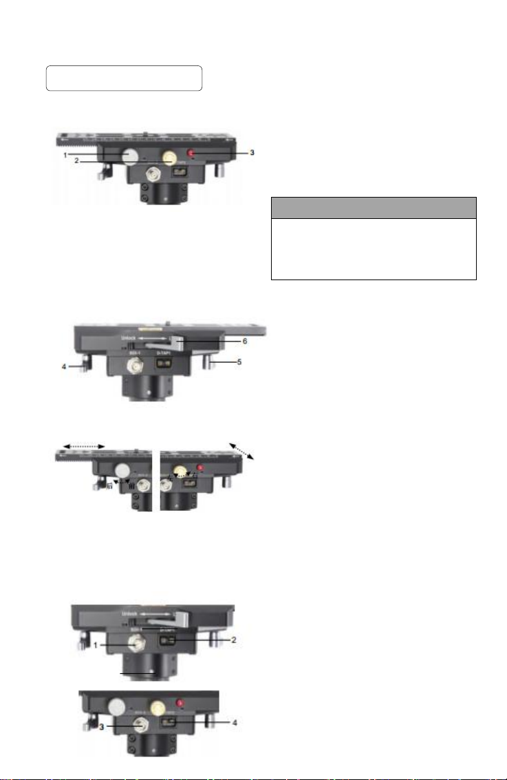
The sled consists of a top stage, gimbal handle, bottom mounting components
(counterweight battery), monitoring components (monitor, remote control circuit)
and telescopic poles. Wear the vest while using, so that the entire support point is
basically on the shoulder and waist; then install the camera extension on the top
stage, connect the power supply and remote control line after putting the camera
on, and adjust the balance.

42021 LAING All right
Parameter Master
Items
Parameter(Inch)
Parameter(Metric)
Arm adaptation
8.8-50.6 lb.
4-23kg
Arm lifting range
29.3 inch
750mm
Arm weight
11.22lb.
5.1kg
Arm pin diameter
0.63inch
16mm
Vest weight
10.34lb.
4.7kg
Vest bust
29.5-57.08inch
750-1450mm
Vest waist
31.1-57.87inch
790-1470mm
Sled Weight
9.68lb.
4.4kg
Dovetail plate size
7.9x2.6x0.35inch
200x65x9mm
Top stage Size
6.1x3.5inch
155x89mm
Central connecting rod
diameter(outer)
1.57inch
40mm
Central connecting rod
diameter(inner)
1.4inch
35mm
Min.height of overall stretch
27.2inch
690mm
Max.height of overall stretch
42.9inch
1100mm
Camera mounting hole
1/4inch 3/8inch
Sled handle hole
0.63inch
16mm
Counterweight
2.2 lb.
1kg (4*0.25kg)
Product net weight
33.44 lb.
15.2kg
Package size
34.3x20.5x13.8inch
870x520x350mm
Gross weight
68.2 lb.
31kg

52021 LAING All right
【Item List】
Product
name
Camera Stabilizer
Model
Master
Quantity
1 set
No.
Part name
Unit
Quantity
Notes
Standard/optional
1
Vest
set
1
Standard
2
Sled
set
1
Standard
3
Arm
set
1
Standard
4
Docking
bracket
set
1
Standard
5
Damping
arm
connector
set
1
Standard
6
Accessories
set
1
1. 6MM hexagon wrench (for
adjusting the arm) 1pc, flat-
head/cross screwdriver 1pcs
2.Screw:3/8x2,1/4x2,M6X60mmx2
3. Power: D-TAP to D-TAP,2pcs
BNC video cable: SDI to SDI 2pcs
4. Counterweight: 0.25kgx4 pcs
5. Pole ZJG05 2pcs
Standard
7
Packing
box
pcs
1
Safety protection aluminum
box
Standard

62021 LAING All right
Know Master
Vest
1. Shoulder buckle
2. Shoulder pads
3.Chest plate
4. Chest pads
5. Chest buckle(Chest relax/tight)
6. Length fix button(Adjust length)
7. Length button
8. Bridge board fixing knob
9. Bridge plate knob
10.Connector with arm
11.Bridge plate
12.Waist pad
13.Waist buckle(Waist relax/tight)
14.Front and rear fine-tuning knobs
for arm
15.Vertical board
16. Cross back strap
17. Lumbar pad
1
2
4
3
5
8
10
9
6
7
11
12
13
16
17
14
15

72021 LAING All right
Arm
1.Arm post(Connect with sled)
2/3 . Titanium spring (light weight, strong rigidity)
4.Forearm adjustment knobs (adjust spring force according to different weight)
5.Rear arm adjustment knobs (Adjust spring force according to different weight)
6. Damping arm connector
7.Arm left and right fine-tuning nut (adjust the left and right)
8.Pole
Sled
1. 200mm dovetail plate
2. Top stage
3.Nosebox(Camera power box video
connection)
4.Gimbal
5.Handle
6.40mm carbon fiber tube (modular design at
the end to make the system maintenance
and upgrade faster and easier)
7. Upper and lower pipe clamps (fix the inner
and outer pipes)
8.Monitor bracket (adjust angle)
9.Bottom (monitor power supply, accessory
power supply and video connection)
10.Battery bottom bracket (adjust angle to
meet user’s demand, the rod can be
extended to increase the inertia of panning)
1
2
4
5
7
6
3
1
2
3
4
7
8
9
10
5
6
8

82021 LAING All right
Sled function overview
Top Stage
1.fore and aft
adjustment knobs(fine-tuning)
2.Left and right adjustment knobs(fine-tuning)
3. Anti-dropping pin (to prevent the camera
from falling off accidentally)
The dovetail plate must be installed into the stage in the
direction of the arrow.Do not
press the anti-dropping pin before clamping
the dovetail plate.
4/5. Horizontal locking knobs (double knob design)
6. Clamping rod (safety lock with drop assist
Gauge, adjustable tension without gasket)
Front and back/left and right adjustment:
Turn the knurled knob marked Fore/Aft
clockwise to move the camera dovetail
back.Turn it counterclockwise to move forward.
(Before insert the dovetail board, set the
clamping lever to the unlock position. after the
adjustment is completed, set the clamping
lever to the lock position.) Turn the knurled
knob marked R/L clockwise to move the
camera dovetail plate to the left . Turn it
counterclockwise to move it to the right.
(Before adjustment, the horizontal locking
button needs to be loosened, while completion
must be locked )
Nosebox(Left and right interfaces)
1/3. SDI port (HD video interface)
2/4.D-TAP port (power interface)
Notes

92021 LAING All right
Gimbal 1. Bearing fixing ring (inner and outer ring
easy to maintain and dustproof)
2. Gimbal bracket
3. Gimbal handle
4. Gimbal armrest
5. Clamping rod
6. Clamping force adjustment screw
To modify the position of the gimbal on
the center rod, the clamping lever must
be opened.
Only when the sled is docked on the stand
or in a horizontal position,can the clamping
lever be opened.
If the lower rod slides up or down, please
loosen the upper and lower rod pipe clamps first
The
clamping force must be appropriate, in case that when
the clamping rod is closed, the clamping force is too
large to make the lower rod slide not smoothly or even
get stuck.
Bottom
1. Horizontal bubble (backlight, high precision)
2. Bracket clamping knob
3. Monitor bracket (rotatable and movable)
4. Monitor shaft (can be rotated 180 degrees)
5. Monitor shaft locking button
6. Monitor bracket lever lock button
7. Post clamp
8. Battery holder lever lock button
9. Battery holder shaft (can be rotated 180
degrees)
10. Battery holder shaft locking button
11.V type gusset seat
12. Monitor bracket rod
13. Battery holder rod
Notes
关
Notes
open
close
open
close

10 2021 LAING All right
Tight
open
close
Move the monitor, please loosen the monitor
Bracket lock knob to move monitor bracket,
re-lock to fix it.
Fine-tune the monitor angle, please loosen the
rod locking knob and re-lock it to fix the monitor.
Rotate the monitor, please loosen the bracket
clamping knob and re-lock it to fix the monitor.
Move the battery holder, please loosen the
battery rod locking knob and slide(The battery
holder can be removed), re-lock and fix the
battery holder.Spin the battery holder, please
loosen the battery holder shaft locking knob.
The monitor bracket slides up or down, please
support the monitor first and loosen the post clamp.
Loose
Loose
Tight

11 2021 LAING All right
Notes
Electronics box
1. Double D-TAP interface (power interface)
2. Dual SDI interface (HD video interface)
3. Counterweight connection thread
Battery box
4.D-TAP power interface
5. Power indicator
6. Toggle switch
7. Power indicator
8. D-TAP power connector
The built-in adjustable step-down module has
the function of voltage stabilization and can also
reduce the voltage according to the demand
(if the voltage needs to be adjusted, the battery
box needs to be disassembled)
Docking bracket 1. Docking bracket plate
2. Anti-drop pin
3. Chain
4. Balance pin
5. Balance bar
6. Balance bar lock screw
7. Bolt lock screw
Bracket Assembling
The bracket connector is designed for brackets with 15.9 mm sockets. Place the docking bracket
on the bracket pin and tighten the horizontal bracket locking screw accurately.
• Only suitable for steel brackets, such as C-shaped
brackets or low brackets, and use sandbags to prevent
the brackets from tilting.
• Make sure that the stand is flush with the surface.
• Make sure that the socket locking screw is fully tightened.
Notes

12 2021 LAING All right
+
-
Rear
臂
Front
+
-
Vest function overview
Loosen the length fixing knob on the breastplate, pull the
length knob, the breastplate can be moved up and down.
Loosen the fixing knob of the bridge board, pull the knob of
the bridge board, the bridge board can be moved up and
down.
The chest buckle and waist buckle are just fine adjustments,
firstly, you should pull the chest pad and waist pad to suitable
tightness ,then press the chest buckle and waist buckle.
When the vest is worn on the body, the shoulder and chest
should not be too tight, and it comfortably fits the body.
The waist pad must be stuck on the hip bone of the body, and
it must be close to the bod,.no gap.
The front and rear fine adjustment knobs and the left and
right fine adjustment nuts on the arm can adjust the angle of
the arm to the vest, from side to side, also to the inside and
outside. The inside and outside are controlled by two
thumbscrews which are pressed on the connecting seat of
the arm.
Two nuts on the arm are used for side-to-side adjustment。
Arm function overview
Adjust the lifting capacity of the arm. The arms of different
stabilizers will be different load-bearing capacity. Each
arm is designed for a specific weight range of the camera.
Change a different camera or
add and remove an accessory, the lifting capacity of the
arm must be adjusted.
The front/rear adjustment knob on the arm can control the
lifting capacity.
Spring tension adjustment of front and rear arms: turn the
wrench clockwise to increase the tension, and vice versa.
Regulating screw
Adjusting wrench

13 2021 LAING All right
Preparation
Install the docking bracket
The docking bracket is used to place and support the sled and arm.
The installation steps are as follows:
1. Open the bracket and place it on the ground, then put the docking bracket on the
bracket pin, and tighten the locking screw, install the M6*60mm screw on the docking
bracket.
2. Take out the sled and place it on the docking bracket pallet, and hang the arm on the
M6 screw。
©
Install battery and monitor
The installed battery and monitor are optional accessories (you need to purchase them),
please confirm whether these items are included in your configuration.
1. Align the V-shaped plug on the bottom of the battery with the V-shaped slot on the gusset,
and then push it in with a little force.
2. Align the screw hole at the bottom of the monitor with the monitor interface screw at the bottom
of sled, then tighten it to fix it.
.

14 2021 LAING All right
Master's "dual dynamic balance" extended range,
combined with the monitor stand,allows to install
batteries and monitors in independently adjustable
positions.
Advantages as below:
• Sufficient counterweight
• The position of the counterweight (monitor and
battery) can be easily adjusted
• The display and battery can move independently
of each other
• When the system is balanced, the batteries can
be moved and placed independently of each other.
• By moving the display and battery to the correct
position, you can easily set up the camera and
weight distribution.
This flexible adjustment ensures that you always
have enough battery power,The multi-function
positioning of the battery achieves perfect dynamic balance.
Install the camera
The camera is mounted on the top stage of the sled
1. Open the clamping lever, press the anti-falling pin, and take out the dovetail plate.
2. Lock the dovetail plate on the bottom of the camera, then put the plate back on the
top stage and lock the clamping lever.
3. Connect the video cable and camera power supply cable
Two basic methods for assembling:
High mode
The camera is mounted on the top of the sled. The height of the camera lens can be
anywhere from the operator’s hop to up over his head. High mode is most commonly used.
Low mode
Here, the sled is turned upside down. The camera is mounted right side up via a special
bracket. The typical height of the lens is between the operator’s waist and his knees. Super
low mode gets the lens on the floor.
Two basic operating positions:
Missionary
When the operator is in Missionary the camera is facing the same direction as the
operator. The monitor is to the operators front; the battery is to the rear. Missionary is an arc
from the camera pointing straight ahead to looking across the operator’s body.
Don Juan
When the camera Is pointed behind the operator, we say he Is in Don Juan. The monitor
is to the operator’s rear; the battery is to the front. Don Juan includes an arc as the camera
looks to the side away from the arm and pans to the rear.

15 2021 LAING All right
Adjust Balance
In order to achieve the ideal effect for the stabilizer, balance adjustment is essential. Precise
balance will directly improve the quality of the picture.The stabilizer should achieve static balance
and dynamic balance before shooting.
Balance adjustment preparation
1. After the camera is installed, please connect the SDI video cable and the power supply
cable of the camera first, install the follow focus and connect the power supply port before
balance adjustment.
2. Before balance adjustment, you need to remove the lens cap and insert the memory
card,complete all the connections to ensure that the camera is fully prepared for
shooting,otherwise, it will affect the balance effect.
3. In the process of balance adjustment, make sure that the power of the camera is turned off.
Static balance adjustment steps
A rig in static balance will hang by the gimbal at a particular attitude:usually upright and with the
post vertical .The three components of static balance are in the three axes: fore and aft, side to
side, and top to bottom.
1. Place the monitor where you can comfortably see it.
2. Move the gimbal up or down depending on the camera weight.
3. Move the battery in and out until the device hangs vertically.
4. Drop test. Perform this test by keeping the stand level, letting go, and calculating the time
it takes from the bottom of the equipment to pass through the vertical. At the beginning, try
to reach a landing time of 2-3 seconds. If the equipment drops too fast, the gimbal needs to
be lowered. If the equipment fall speed is too slow, the gimbal needs to be risen and increase
the equipment bottom weight . (Note: When you loosen the clamping rod of gimbal, the
equipment must be level.)
5.Achieve balance by fine-tuning the front and rear/left and right adjustment knobs.
Dynamic balance adjustment steps
Equipment in dynamic balance can be horizontal hunting. Regardless of the rotation speed,
the support rod will remain vertical. Dynamic balance equipment is static balanced, but
completely static balance equipment may not be in dynamic balance. Only the spin balance
can be detected whether the equipment is in dynamic balance.
1. All elements (cameras, monitor and batteries/electronics) must be arranged be lined up
on the same vertical plane.
2.To start, the rig must be in static balance, with a drop time of 3 seconds or more.
3. Rotate the equipment by itself, if it rotates smoothly, the equipment is in dynamic balance,
if not, go to the next step.
4. Move the battery in or out about 1/2 inch. Adjust the static balance of the camera and
spin again.
5. If it still does not work, move the battery in the opposite direction, 1/2 inch
away from the original position. If it is better, move the battery 1/4 inch in the same direction.
Adjust the static balance of the camera.
6. Repeat the above steps until the rig pans flat.

16 2021 LAING All right
Wearing of the vest
The vest needs to fit like a second skin, with no gaps between the shoulders and the shoulder
pads, the chest pads should cover the thick ribs, and the waist pads are concentrated on the hip
bones. The vest is in good condition, fits tightly, and can get feedback in time from the
equipment,that will help you adjust your posture to balance the equipment.
Wearing steps
1. Loosen all straps, including cross straps. Open the left side of the vest-the buckles on the
shoulders, chest, waist.
2.Take the vest off from your right shoulder, fasten the left shoulder buckle.
3. Pull the vest down so that it fits tightly on your shoulders. Keep the board vertical.
4. Fasten the chest strap close to your ribs.
5. Pull the vest down on your shoulders.
6. Fasten the buckle on the lower left, adjust the waist pad. Your hip bone should be directly
behind the waist pad. If the vest is too long or too short, you can adjust its length by releasing
the lock button on the breastplate and then moving the vertical plate up and down.
7. Fasten the chest button and waist button on the front of the vest.
8.Connect and tighten the cross straps on the back of the vest. They are used to prevent slippage
of the vest and ease some side shifts of the equipment.
Note: Everyone's figure and body shape are different. You may need to adjust further to make
the vest fit you closely. You can add or remove the filling at will, lengthen or shorten the strap.
Install and remove of the arm
The arm connector is the interface between the arm and the vest.
Installation and debugging steps
1. Insert the arm connecting plug into the socket on the vest.
2. Using the front and rear fine-tuning knobs of the arm to fix the arm in place. When the top
screw is turned inward, the angle of the arm is pulled towards to the photographer. The top
screw is screwed out, the equipment tends to drop away from the photographer.
3. Using the left and right fine-tuning knobs of the arm to adjust the arm laterally. If the
equipment fall to the left, unscrew the top screw (turn the nut counterclockwise). If the
equipment fall to the right, screw in the top screw (turn the nut clockwise).
4. Put the handle of the gimbal on the arm, then adjust the tension of the part (forearm) of the
arm which is close to the gimbal. Adjust the forearm knob, but only when the front and rear
arms are slightly upward, the adjustment knob can be easily turned. For more force, twist to
the right (tighten); for less force, twist to the left (loosen). Then adjust the part of the arm near
the vest (the back arm) in the same way. Finally, find the right strength so that the back arm
can "follow" the forearm when you are up and down.
If you find the rear arm is following, and then
suddenly "cocked" up and down (that is,
across the center), it may be caused by your
posture, rather than a problem with the arm.
Readjust your posture, relax, and then try to
go up and down. This usually solves the
problem.
Notes

17 2021 LAING All right
Precautions for use:
Safe Use
1. Before using the equipment, check the screws of each connection position are loose or
abnormal, and make sure the problem is eliminated before using.
2. Training or shooting difficult actions requires the help and cooperation of an assistant.
3. When shooting on a moving vehicle, please fasten your seat belt and wear appropriate
personal protective equipment.
4. Avoid to use the equipment while running on ice and soft sand.
Maintenance
1. After using, the equipment should be disassembled and put it into the box and locked, and
placed in a cool and dry place. Don't put it any where in case that accessories lost or bumps,
affect the use of equipment.
2. Do not place the device in a humid environment or in the hot sun, which will easily deform
and damage the internal precision parts.
3. The equipment connection, top stage and component installation place should be kept clean.
If there is debris or oil residue on the connection of the equipment, after disconnecting the
power, wipe it with a damp cloth dampened with a neutral detergent. Do not wipe with a rough
surface or corrosive detergent or scrape with a knife to avoid damage the protective layer of
the surface.
4. Grease to the rotating part of the gimbal and arm regularly for maintenance.
Product after-sales service
1. All products sold by our company will provide free installation instructions
2. Luanyi brand film and television equipment products provide three-year warranty and lifetime
maintenance services
3. During the warranty period, non-man-made faults can enjoy free warranty and replacement,
and the replenishment time is guaranteed within 15 days
4. During the warranty period, if the product needs to be repaired due to man-made damage,
the product can be sent back to the manufacturer for repair, repair fees is free, only the cost of
the accessories is charged, and the freight out and home will be on buyer's charge.

2021 LAING All right
This manual is subject to update without notice.
You can check the latest version of "User Manual" on the official website of Luanyi
http://www.szlaing.com
Table of contents
Other Laing Camera Accessories manuals