Lamarche 21Q User manual

I-UPS
Modbus TCP and Serial
SCADA INTERFACE
OPTION 21Q / 21S
INSTRUCTIONS
This manual is valid for I-UPS equipped RS-485 serial port.
Option 21Q - TCP/IP and RS-232 serial provided on 383S Communication Board
Option 21S –RS-232 serial provided via RS-485 to RS-232 converter.
ECN/DATE
CPN 147722
106 BRADROCK DRIVE
DES PLAINES, IL. 60018-1967
(847) 299-1188
FAX: (847) 299-3061
ISSUE DATE: ECN 23295 11/2022
INSTRUCTION DRAWING NUMBER:
P25-LOPT21QS-I-UPS-01

Page 2 of 12
Default Settings
The LaMarche Communications Card is shipped with the following settings.
Settings CANNOT be changed.
Port: RS485 (RS-232 port and TCP/IP communication can be selected).
Baud Rate: 115200
Data Bits: 8
Stop Bits: 1
Parity: None
Address: 0
Board Configuration
The communications card may be configured for RS232, TCP communications.
SW2 configures the board for either Serial or TCP/IP communications.
SW4 –leave in RS-232 communication. For RS-485 communication –connect directly to the RS-485 port
in the unit. The RS- 485 port on the communication card is not used.
SW3 –not used in this version of the board.
The photo below shows the location of the dipswitches of the communications board.
Setting the Modbus Address, Baud Rate & Parity
Serial settings cannot be changed.

Page 3 of 12
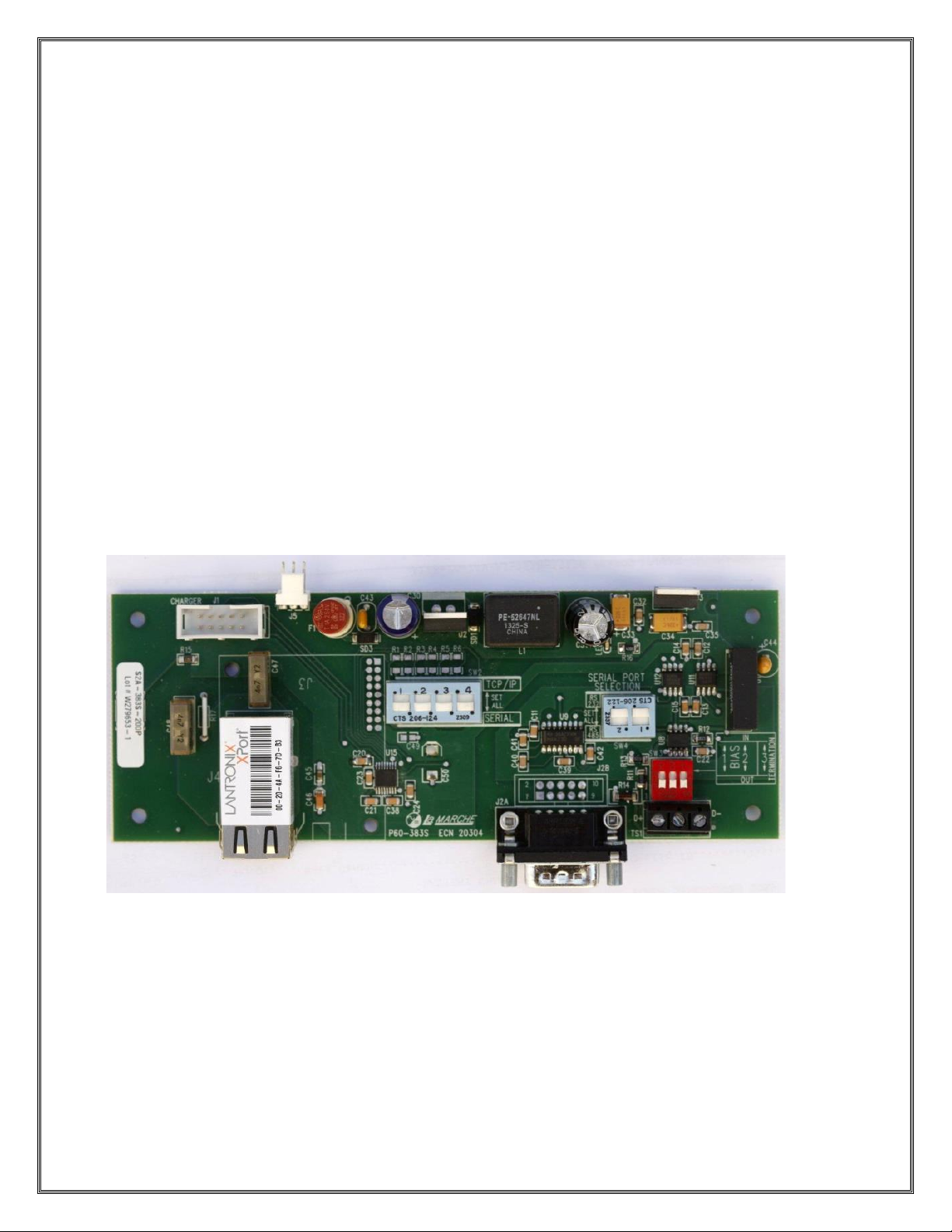
RS232 & RS485 Serial Applications
For RS-232 –connect to the S2A-383S-20D1 PCB. Make sure the dip switch SW4 is set to RS-232. For
RS-485 communication, connect directly to the RS-485 port in the unit –positions A (D-) and B (D+).
Disconnect the serial converter wired to this port. Move the Red and Black wires labeled D+ and D- from
A and B positions to positions C and D. The converter is used to communicate to the S2A-383S-20D1
PCB)
TCP/IP Applications
To configure the card for TCP/IP applications you need to configure the boards dipswitches on the S2A-
383S-20D1 PCB.
You will also likely want to change the IP, Subnet and Gateway. To accomplish this please refer to the
next section.
Changing the TCPIP Settings
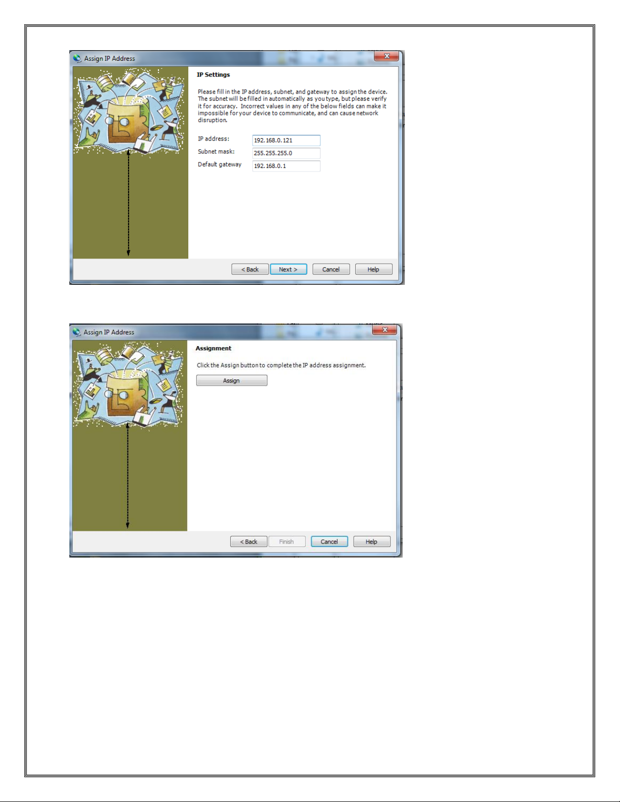
The RTU to TCP/IP module is set at the factory as follows:
IP Address: 192.168.0.6
Netmask: 255.255.255.0
Gateway: 192.168.0.1
TCP Port Number: 502
To change the TCPIP settings it is necessary to load and install the DeviceInstaller Software provided by
Lantronix Inc. from the following URL:
http://www.lantronix.com/device-networking/utilities-tools/device-installer.html
Once this software is installed you should reconfigure your Network Adaptor to the same subnet (see
default settings above) as the Lantronix device. Connect the device to your laptop/PC using a null-modem
for a direct connection. Use a straight through if connecting through a switch or hub. If the device is
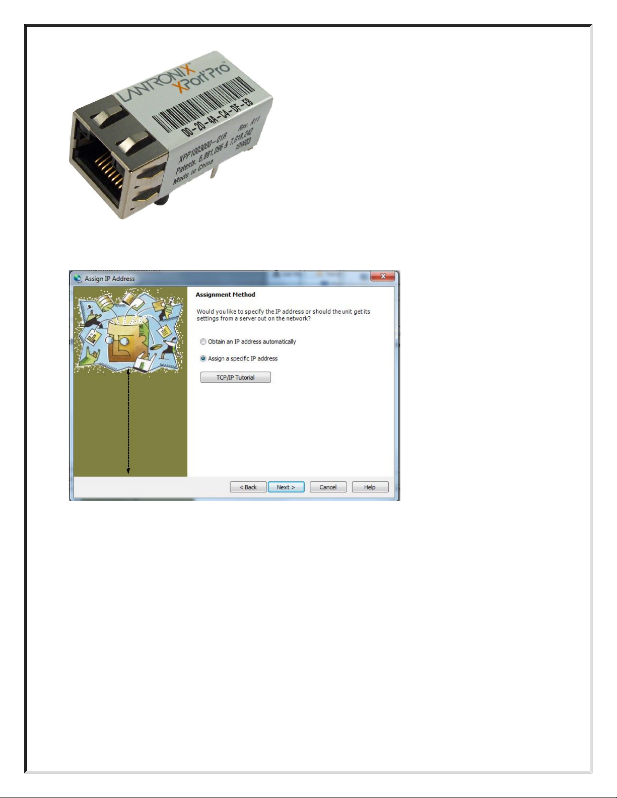
powered when you run the DeviceInstaller it will automatically begin a search and find the device. If
DeviceInstaller is running when the device is connected the Search command on the Toolbar Menu will
locate the device. Once the device is located, the screen should appear as pictured below.

Page 4 of 12
To assign the desire IP settings press the Assign IP button on the Toolbar. This will bring up the
following screen:
The Device Identification is located on the device itself as described in the dialog text above. An example
of the Lantronix device is pictured below.

Page 5 of 12
In the example above the Device Identification would be 00-20-4A-C4-DF-E8. Note this is unique to each
device. After entering the ID press Next.
This dialog presents a choice between assigning an IP dynamically which would allow the device to
operate on a network with a DHCP server however it is recommended that a specific IP address be
assigned so it can be referenced directly on a SCADA Network.
Selecting “Assign a specific IP address” will bring up the following dialog:

Page 6 of 12
Enter your desired IP settings and press Next.
Pressing Assign will start the process of programming the device to the new IP Settings.
A progress bar and Status will appear indicating a successful operation as shown below:

Page 7 of 12
Pressing Finish will complete the IP setting change process. The DeviceInstaller Application can now be
closed.
LaMarche Modbus Implementation
MODBUS - RTU, BAUD RATE - 115200, PARITY - NONE,
SLAVE ID - 0, STOP BIT - 1 BIT
Sr No.
PARAMETER DETAIL
MAIN CARD
Modbus
Register
Address
Variable Type
UNIT
Range
1
M_HT_TEST_LOAD_KVA
2
M_HT_TEST_START_VOL
30002
unsigned int
kva
3
M_HT_TEST_END_VOL
30003
unsigned int
volt/cell
4
M_BATT_HEALTH_STATUS
30004
unsigned int
volt/cell
5
M_CT_TEST_LOAD_KVA
30005
unsigned int
%
6
M_CT_TEST_START_VOL
30006
unsigned int
kva
7
M_CT_TEST_END_VOL
30007
unsigned int
volt/cell
8
M_CT_TEST_PERCENTAGE
30008
unsigned int
volt/cell

Page 8 of 12
9
M_BATT_ test _RESULTS
30009
unsigned int
%
10
M_CONFIG_ACKNOWLEDGEMENT
30010
unsigned int
NA
11
M_PHASE_SHIFT
30011
unsigned int
NA
0x1111/
0x1357
12
M_BATT DISCHARGE ELAPSED TIME
30012
unsigned int
NA
13
M_REMOVED AH
30013
unsigned int
Minutes
14
M_BATTERY SOC
30014
unsigned int
AH
15
M_AH RATING
30015
unsigned int
%
16
M_VERSION
30016
unsigned int
AH
17
M_GRID_VOLTAGE_PH1
30017
unsigned int
NA
18
M_GRID_CURRENT_PH1
30018
unsigned int
V
19
M_GRID_FREQUENCY_PH1
30019
unsigned int
A
20
M_GRID_VOLTAGE_PH2
30020
unsigned int
Hz
21
M_GRID_CURRENT_PH2
30021
unsigned int
V
22
M_GRID_FREQUENCY_PH2
30022
unsigned int
A
23
M_GRID_VOLTAGE_PH3
30023
unsigned int
Hz
24
M_GRID_CURRENT_PH3
30024
unsigned int
V
25
M_GRID_FREQUENCY_PH3
30025
unsigned int
A
26
M_GRID_TOTAL_ENERGY
30026
unsigned int
Hz
27
M_GRID_TOTAL_POWER
30027
unsigned int
Kwh
28
M_GRID_AVG_POWER_FACTOR
30028
unsigned int
Kw
29
M_BATTERY_VOLTAGE
30029
unsigned int
NA
30
M_BATTERY_CHG_CURRENT
M_BATTERY_DISCHG_CURRENT
30030
unsigned int
V
31
M_BATTERY_CKWH
30031
unsigned int
A
32
M_BATTERY_DKWH
30032
unsigned int
Kwh
33
M_RECTIFIER_VOLTAGE
30033
unsigned int
Kwh
34
M_RECTIFIER_CURRENT
30034
unsigned int
V
35
M_INVERTER_VOLTAGE
30035
unsigned int
A
36
M_INVERTER_LOAD
30036
unsigned int
V
37
M_INVERTER_FREQUENCY
30037
unsigned int
A
38
M_INVERTER_ENERGY
30038
unsigned int
Hz
39
M_INVERTER_POWER
30039
unsigned int
Kwh
40
M_INVERTER_POWER_FACTOR
30040
unsigned int
Kw
41
M_BYPASS_VOLTAGE
30041
unsigned int
NA
42
M_BYPASS_FREQUENCY
30042
unsigned int
V
43
M_SYSTEM_TEMP
30043
unsigned int
Hz
44
M_TEMPERATURE2
30044
unsigned int
*C
45
M_CHARGER_STATUS[0]
30045
unsigned int
*C
46
M_CHARGER_STATUS[1]
30046
unsigned int
NA
47
M_CHARGER_STATUS[2]
30047
unsigned int
NA
48
M_INVERTER_STATUS[0]
30048
unsigned int
NA
49
M_INVERTER_STATUS[1]
30049
unsigned int
NA

Page 9 of 12
50
M_SYSTEM_STATUS[0]
30050
unsigned int
NA
51
M_SYSTEM_STATUS[1]
30051
unsigned int
NA
52
M_SYSTEM_STATUS[2]
30052
unsigned int
NA
53
M_BYPASS_STATUS[0]
30053
unsigned int
NA
30054
unsigned int
NA
HMI
55
P_BATTERY_TEMP
56
P_AMBIENT_TEMP
30055
unsigned int
57
P_COMMUNICATION_STATUS
30056
unsigned int
STATIC SWITCH CARD
30057
unsigned int
59
S_INVERTER_VOLTAGE,
60
S_INVERTER_LOAD,
30058
unsigned int
V
61
S_INVERTER_FREQUENCY,
30059
unsigned int
A
62
S_UPS_OUTPUT_ACTIVE POWER
30060
unsigned int
Hz
63
S_UPS_OUTPUT_APPARENT
POWER
30061
unsigned int
Kwh
64
S_UPS_OUTPUT_POWER_FACTOR
,
30062
unsigned int
Kw
65
S_BYPASS_VOLTAGE,
30063
unsigned int
NA
66
S_BYPASS_LOAD,
30064
unsigned int
V
67
S_BYPASS_FREQUENCY,
30065
unsigned int
A
68
S_FINAL_OUTPUT_VOLTAGE,
30066
unsigned int
Hz
69
S_FINAL_OUTPUT_CURRENT,
30067
unsigned int
V
70
S_FINAL_OUTPUT_FREQUENCY,
30068
unsigned int
%
71
S_TEMPERATURE1,
30069
unsigned int
Hz
72
S_TEMPERATURE2,
30070
unsigned int
*C
73
S_VERSION,
30071
unsigned int
*C
74
S_CONFIG_ACKNOWLEDGEMENT
30072
unsigned int
NA
75
P_Peripheral_version
30073
unsigned int
NA
0x2222 /
0x2468
76
S_INVERTER_STATUS[0],
30074
unsigned int
NA
77
S_SYSTEM_STATUS[0],
30075
unsigned int
NA
78
S_SYSTEM_STATUS[1],
30076
unsigned int
NA
79
S_BYPASS_STATUS[0],
30077
unsigned int
NA
80
S_BYPASS_STATUS[1],
30078
unsigned int
NA
30079
unsigned int
NA
FLAG BYTE
DESCRIPTION
BIT NO

Page 10 of 12
M_CHARGER_STATUS[0]
ChargerFlags.Charger_off_SHORT_CKT
Bit 8
ChargerFlags.Charger_off_CV_HIGH
Bit 7
ChargerFlags.Charger_off_MAINS_FAULT
Bit 6
ChargerFlags.Charger_off_OVERHEAT
Bit 5
ChargerFlags.MAINS_ABSENT
Bit 4
ChargerFlags.MAINS_1_PHASE_ABSENT
Bit 3
ChargerFlags.ALARM_CHARGER_OVERHEAT
Bit 2
M_CHARGER_STATUS[1]
ChargerFlags.CHARGER_ON_STATUS
Bit 1
ChargerFlags.FREQ_OUT
Bit 8
ChargerFlags.MAINS_HIGH_PH3
Bit 7
ChargerFlags.MAINS_HIGH_PH2
Bit 6
ChargerFlags.MAINS_HIGH_PH1
Bit 5
ChargerFlags.MAINS_LOW_PH3
Bit 4
ChargerFlags.MAINS_LOW_PH2
Bit 3
ChargerFlags.MAINS_LOW_PH1
Bit 2
M_CHARGER_STATUS[2]
ChargerFlags.BATTERY_CAPACITY_TEST_RESULT
Bit 1
ChargerFlags.BATTERY_CAPACITY_TEST
Bit 8
ChargerFlags.BATTERY_HEALTH_TEST_RESULT
Bit 7
ChargerFlags.BATTERY_HEALTH_TEST
Bit 6
ChargerFlags.FLOAT_EQ_MODE
Bit 5
ChargerFlags.CHARGING_DONE_STATUS
Bit 4
ChargerFlags.BATTERY_CAPACITY_END
Bit 3
ChargerFlags.Rectifier_Drive_is_on
Bit 2
M_INVERTER_STATUS[0]
InverterFlags.Inv_off_OPEN_CKT
Bit 1
InverterFlags.Inv_off_SHORT_CKT
Bit 8
InverterFlags.Inv_off_OVERLOAD
Bit 7
InverterFlags.Inv_off_OUTPUT_HIGH
Bit 6
InverterFlags.Inv_off_OUTPUT_LOW
Bit 5
InverterFlags.Inv_off_BATT_HIGH
Bit 4
InverterFlags.Inv_off_BATT_LOW
Bit 3
InverterFlags.Inv_off_OVERHEAT
Bit 2
M_INVERTER_STATUS[1]
InverterFlags.Alarm_OVERLOAD
Bit 1
InverterFlags.Alarm_BATT_HIGH
Bit 8
InverterFlags.Alarm_BATT_LOW
Bit 7
InverterFlags.ALARM_INVERTER_OVERHEAT
Bit 6
InverterFlags.INVERTER_ON_STATUS
Bit 5
InverterFlags.OutputZeroXingError
Bit 4
SWFlag.SwitchIsON
Bit 3
End_of_discharge
Bit 2
M_SYSTEM_STATUS[0]
Flags2.FinalVoltageRefOK
Bit 1

Page 11 of 12
Flags2.BypassVoltageRefOK
Bit 8
Flags2.InvCurrentRefOK
Bit 7
Flags2.InvFBVoltageRefOK
Bit 6
Flags2.MainsVoltageRefOK
Bit 5
Flags2.MainsCurrentRefOK
Bit 4
Flags2.LoadCurrentRefOK
Bit 3
INVERTER NTC OPEN
Bit 2
M_SYSTEM_STATUS[1]
Flags2.DC_AUX_SWITCH
Bit 1
flage2.Flag reset done
Bit 8
Flags2.INPUT_AUX_SWITCH
Bit 7
Flags2.DC_contractor_ON
Bit 6
Flags2.UPPER_INV_FAN_FAIL
Bit 5
Flags2.LOWER_INV_FAN_FAIL
Bit 4
Flags2.FUSE_FAIL
Bit 3
Flags2.PhaseInSync
Bit 2
Bit 1
M_SYSTEM_STATUS[2]
Flags2.SYSTEM_3PH_1PH_OUT 0-
3Phase, 1-1Phase
Flags2.VOLTAGE_220V_OR_120V 0-220,
1-120
Bit 8
Flags2.FREQUENCY_50HZ_OR_60HZ 0-50,
1-60
Bit 7
Battery_not_connected 1
battery not connected
Bit 6
Inverter_output_breaker
Bit 5
HT_IN_PROGRESS
Bit 4
ABORT_HT
Bit 3
START_HT
Bit 2
M_BYPASS_STATUS[0]
ChargerFlags.BYPASS_FREQ_OUT
Bit 1
ChargerFlags.BYPASS_HIGH
Bit 8
ChargerFlags.BYPASS_LOW
Bit 7
ChargerFlags.BYPASS_ABSENT
Bit 6
NA
Bit 5
Battery test in Progress
Bit 4
Battery Test Complete
Bit 3
Start_CT
Bit 2
Bit 1

Page 12 of 12
S_INVERTER_STATUS[0]
Flags2.INVERTER_FAULT
InverterFlags.Inv_off_OVERLOAD
Bit 8
Flags2.INVERTER_FAULT_FAST_SENSE
Bit 7
Flags2.INVERTER_FREQ_OUT
Bit 6
Flags2.INVERTER_VOLTAGE_HIGH
Bit 5
Flags2.INVERTER_VOLTAGE_LOW
Bit 4
Flags2.INVERTER_ABSENT
Bit 3
Flags2.system in inverter
Bit 2
S_SYSTEM_STATUS[0]
Flags2.OPCurrentRefOK
Bit 1
Flags2.OPVoltageRefOK
Bit 8
Flags2.BypassCurrentRefOK
Bit 7
Flags2.BypassVoltageRefOK
Bit 6
Flags2.InvFBVoltageRefOK
Bit 5
TransferTestResult[2]
Bit 4
Bit 3
M_BATT_HEALTH_STATUS
Value -0 to 100
Load Insufficient - 155
Battery Low During Test - 156
Utility Absent During Test - 157
Rectifier Fail - 158
Inverter Fail - 159
Battery Over Heat - 160
162- Operation Manualy Aborted
163 - Load Change
M_BATT_CT_RESULTS
Fail -0 Pass -1
Load Insufficient - 155
Battery Low During Test - 156
Utility Absent During Test - 157
Rectifier Fail - 158
Inverter Fail - 159
Battery Over Heat - 160
TransferTestResult >
0- Successful
1- Inverter Fail
2- bypass source fail
This manual suits for next models
1
Table of contents
Other Lamarche Recording Equipment manuals