Pribusin RCI-100 Series User manual
Manufacturers of Process
Controls and Instrumentation
Instruction Manual
For Technical Assistance And Questions Call
USA: (734) 677-0459 CANADA: (905) 660-5336
Model:
Serial #:
Function:
XXX=MDM Modem Dial-Up
Communication:
RCI-100-XXX
(If special or required)
1 “Dry” Contact and 1 Analog Input
Input:
Remote Control Signal Interface
XXX=SER: RS-232/485
Output: 1 Form ‘C’ Contact and 1 Analog Output
XXX=FSK: Leased Line
XXX=RF2: 2.4 Ghz Wireless
XXX=RF9: 900 Mhz Wireless
Power:
24 VDC
117VAC, 50/60Hz
240 VAC, 50/60Hz

Restocking Policy
Page v
Warranty Policy
All product returned to Pribusin Inc. in prime condition (not
damaged, scratched or defaced in any way) within seven (7)
months from the original date of shipment is subject to a 50%
restocking charge. All product must be accompanied by a
Return Authorization number (RA number) which must be
obtained from Pribusin Inc. prior to returning any product.
After seven (7) months from the original date of shipment,
products cannot be returned for restocking.
Custom designed products, modified products or all non-
standard products may not be returned for restocking.
Pribusin Inc. warrants equipment of its own manufacture to be
free from defects in material and workmanship, under normal
conditions of use and service, and will replace any component
found to be defective, on its return to Pribusin Inc.,
transportation charges prepaid, within one year of its original
purchase. Pribusin Inc. will extend the same warranty
protection on equipment, peripherals and accessories which is
extended to Pribusin Inc. by the original manufacturer. Pribusin
Inc. also assumes noliability, expressed or implied, beyond its
obligation to prelace any component involved. Such warranty
is in lieu of all other warranties, expressed or implied.

Function:
The RCI-100-MDM is a bi-directional dial-up
communication system that exchanges the status of 1
dry contact input and 1 analog input between a host and
remote unit or a PC equipped with a modem. A basic
system consists of A) one host station and one or more
remote station(s) B) several remote stations and
one PC with a modem.
In system A), the host unit can be set to interrogate the
remote unit(s) periodically or when required. Remote
units may also be configured to call the host when
required. One host may operate several remote units.
In system B), a PC can call several remote units or
alternately, remote units may call the PC when required
LabVIEW & Visual BASIC drivers are provided for user
software development on PC’s.
OR
Connection:
Units are connected via a standard dial-up voice grade
line. Regular J11 Phone Jacks make for easy
installation. When connecting units on a PBX system
make sure it can accept analog modem transmissions.
Serial systems connect via standard modem cable.
Standard Features:
Bi-directional Communication using Phone Line
Dial-Out Programmable for: Status/Setpoint Change,
Incremental Signal Change and Timed Interval
Point-to-Point or Host-to-Multi-Point Operation
1 Dry Contact and 1 Analog Input
1 'C' Relay Contact and 1 Analog Output
Configurable to Initiate A Call
Uses Standard Voice Telephone Line
No Calibration Required
Microprocessor Controlled for High Accuracy
Power: 117 VAC 50/60 Hz (Optional 24 VDC)
Built-in Overvoltage Protection on Telephone Line
High Noise Rejection
CSA and NRTL Approved (LR51078)
and/or Answer
Specifications:
Transmission Medium: Analog Voice Grade Phone Line
BAUD Rate: 2400 BAUD typ., 9600, 14.4K available
Operating Temperature: -20 Deg.C. to +50 Deg.C.
Relay Contacts: 10A 1/8Hp @ 125VAC
6A 1/8Hp @ 277VAC
Power: 117 VAC, 60/50 Hz
(24VDC Available)
Enclosure: NEMA4X (NEMA12 available as an option)
Model: RCI-100-MDM
Dial-Up Remote Control Signal Interface
Page J05
Manufacturers of Process
Controls and Instrumentation

Enclosures & Dimensions:
Connection:
Page J05
RCI-100-MDM
System A
System B
Options:
D - 8-Digit Scanning Display
(Add letters to end of
Model Number)
Manufactured By:
Modem
1 Analog
1 Contact
1 Analog
1 Contact
1 Analog
1 Contact
1 Analog
1 Contact
2 Analog
2 Contact
2 Analog
2 Contact 1 Analog
1 Contact
1 Analog
1 Contact
1 Analog
1 Contact
1 Analog
1 Contact
9.59”
7.71” 4.60”
www.pribusin.com
CANADA:
Pribusin Inc.
101 Freshway Dr. Unit 57
Concord, Ontario, L4K 1R9
Ph: (905) 660-5336
Fx: (905) 660-4068
USA:
Pribusin Inc.
743 Marquette Ave.
Muskegon, MI 49442
Ph: (231) 788-2900
Fx: (231) 788-2929
Rev.B Subject to change without notice


..\Manuals\RCI-100-MDM rev.B.doc Page 1 of 16
RCI-100 Connections:
The RCI-100 is the main board of an RCI-100-XXX Telemetry system. It provides the input and output
signal connections as well as the power supply for the unit. A separate communications board is
added to the RCI-100 to allow it to communicate with other units. This communications board may
have its own configuration that is in a separate section of this manual. The following configuration
applies only to the RCI-100 board and is common to all communications interfaces.
AC Power & Fuse:
The RCI-100 is typically powered from 120VAC and protected by a 125mA
SLOBLO fuse. It can be wired for 240VAC operation by removing (de-
soldering) power jumpers J1 & J2 and installing (soldering) jumper J3.
When changing the RCI-100 to 240VAC power make sure to change the
fuse to half of its value, 62mA. This is important since at 240VAC the RCI-
100 requires only half the current as if it were powered from 120VAC.
Proper protection is only achieved by reducing the fuse value as mentioned
above.
DC Power & Battery Backup:
The RCI-100 may also be powered from a 24VDC source which could be a battery
or a DC power supply. The 24VDC power input is polarity protected with a fuse to
prevent damage to the RCI-100 by inadvertent reverse polarity. A DC fuse
provision is also provided if this power option is utilized. Insert a 5A automotive
type blade fuse into the Battery Fuse socket.
..\Manuals\RCI-100-MDM rev.B.doc Page 2 of 16
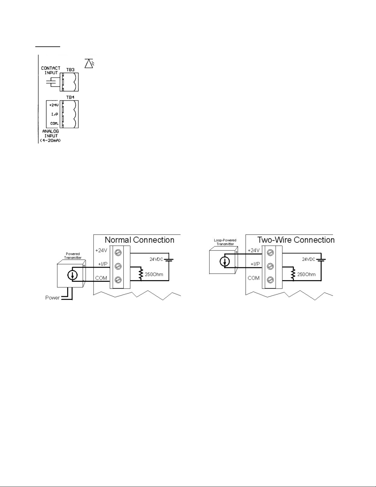
Inputs:
The RCI-100 has one dry contact input and one 0-20mA input. The dry contact
input is excited with 24VDC and will source approximately 20mA when the
contact is closed. A red LED lights up when the contact input is closed.
The analog input is configured as a 0-20mA input and has a 250Ωinput
impedance. The input terminal has three connections: +24V, I/P, COM. The
+24V power output may be used to power field transmitters. Up to 500mA may
be used to power a transmitter. The input signal is connected to I/P(+) and
COM(-).
The analog input is connected to the RCI-800 in two fashions: 1) Normal (3-wire connection) or 2) two-
wire connection. On a 3-wire connected input, an external power supply or the +24V power output
terminal of the RCI provides power to the field transmitter. The field transmitter has a current source
that provides the 4-20mA signal back to the RCI-100. If using the power supply of the RCI-100, the
field transmitter may draw up to 125mA.
On a 2-wire connected input, the field transmitter receives power from the RCI-100 and superimposes
the signal onto the power return path. A maximum of 20mA will flow in such a connection. Make sure
to consult the field transmitter manual to determine how to connect it to the RCI-100.

..\Manuals\RCI-100-MDM rev.B.doc Page 3 of 16
Outputs:
The RCI-100 has one form ‘C’ relay contact output and one 0-20mA analog
output. The relay contact is capable of switching 120VAC, 10A or 240VAC,
6A. An energy absorbing varistor is installed across each contact to limit
switching transients. A second relay contact acts as a communications fail
indicator. If no communication occurred within 30 seconds, this relay
contact will energize. Upon re-established communication this relay will de-energize again.
The analog output is typically configured as a 0-20mA output and can drive into a 1000Ω
load, provided that the power supply to the unit is not below 24VDC. The output is not
isolated from the input. Care must be taken when connecting the output to different
devices so that no inadvertent ground loops are established.
Output Calibration & Input Testing:
The output on the RCI-100 is factory calibrated and should not require any
adjustments. To check the calibration of the output and relays use switch SW2-7 &
SW2-8 as shown below to set them to known states. If an output should require some
adjustment, close SW2-8 only and turn the OUTPUT CALIB. trim pot until the output
reads 20mA.
If both switches are CLOSED, the analog and contact inputs are passed straight
through to the analog and relay outputs. This may help in troubleshooting input and
output signals.
Make sure both switches are OPEN before resuming normal operation.
Battery Charger:
The RCI-100 has a battery connection that allows the system to remain powered up in the case of main
power failure. The battery charger is designed to work with three (3) 6Volt lead-acid or gell-cell
batteries. Switch SW2-6 to the CLOSED position to activate the battery charger. The charging LED
will come on when the batteries are charging.
SW2-7 SW2-8 Function
OPEN OPEN Normal Operation
OPEN CLOSED Outputs=20mA, Relays=Energized
CLOSED OPEN Outputs=0mA, Relays=De-energized
CLOSED CLOSED Outputs=Inputs, Relays=Contact Inputs

..\Manuals\RCI-100-MDM rev.B.doc Page 4 of 16
RCI-100 Configuration:
The RCI-100 requires no configuration other than for its communication fail operation. In the event of a
communications failure on the communications board, the RCI-100 can be set up to take various
actions on its outputs. This may be desirable in order to place connected devices into a safe operating
mode. By default factory setting, all outputs remain at their last known state if a communications failure
occurs.
* If SW2-3=CLOSED then the analog output will ramp to the setting of K1.
The output will change at a rate determined by the setting of K2. The
settings of the trim pots can be read on test points TP1,2 using a
voltmeter. The test points read a voltage of 0-5V for a 0-100%
adjustment.
where, Output = 0-20 (mA) and Ramp Rate = 0-60 (seconds) (5 sec. minimum)
SW2- Function OPEN CLOSED
1 Relay Fail Mode No Change See SW2-2
2 Relay Fail Status De-Energize Energize
3 Output Fail Mode No Change Ramp to K1*
4
5
6 Battery Charger Off On
7 I/O Calibration
8 I/O Calibration
Volt
Output
TP 5
20
1×= Volt
RampRate
TP 5
60
2×=

..\Manuals\RCI-100-MDM rev.B.doc Page 5 of 16
MDM Communication Option:
The -MDM communications option to the RCI series utilizes a 2400-BAUD modem to exchange the
signal data between a host and its remote(s). There are two types of Operating Modes that can be
configured: 1) Answer-Only and 2) Answer-and-Originate.
In Answer-Only mode the RCI-100-MDM will only answer incoming calls. It will not initiate calls to
other devices. This is useful when only periodic data exchange is required. Typically a computer or
PLC places a telephone call via a standard modem, the RCI-100-MDM answers and the two can now
exchange data until the computer or PLC terminates the call.
In Answer-and-Originate mode the RCI-100-MDM operates just like in the Answer-Only mode with the
additional capability of placing a call to another RCI-100-MDM or to a computer or PLC. A
configuration procedure allows the programming of events or time intervals when the RCI-100-MDM is
to place a call. This is useful where unattended, periodic data exchange is necessary. It is also useful
when long distance charges apply to a call since the units can be programmed to communicate only
when there is a change of status at one site or the other. Both units can be programmed to operate in
the Answer-and-Originate mode thus providing bi-directional status change updates.
Modem configuration is done via a bank of DIP switches. The switches are located on the
communications board just to the left of the telephone jack. They are either a slanted rocker type that
flips up for OFF and down for ON or a flat rocker type that are marked OPEN for OFF and/or
CLOSED for ON.
In Answer-Only mode, SW1 is used exclusively to set
all operating parameters (see Answer-Only Mode
Configuration below). In Answer-and-Originate
mode, SW1 is not used and all switches must be in
the OFF position. Instead the RS-232 connection is
used to exchange a configuration file with a PC or
laptop. This is necessary because of the large
number of parameters that are required to be
configurable for flexible dialing operation (see
Answer-and-Originate Mode Configuration below).
Answer-and-Originate Topologies:
The -MDM communications option to the RCI series utilizes dial-up telephone transmissions to
exchange the signal data between a host and its remote(s). There are two types of Topologies that
can be configured: 1) Point-to-Point and 2) Host-to-Multipoint.
In a Point-to-Point
topology one host
communicates with one
remote. The two
exchange all their
signals with one another.
The remote is configured
as remote #1 even
though it is the only remote in the system.

..\Manuals\RCI-100-MDM rev.B.doc Page 6 of 16
In a Host-to-Multipoint
topology one host
communicates to several
remotes. Each remote is
assigned an address
(1,2,3, etc.) so that the
host may distinguish
between them. There
may at most be as many
remotes as there are
inputs & outputs on the
host.
For example, an RCI-200
system, having two
analog/contact inputs and outputs, may communicate with two RCI-100 remotes each having one
analog/contact input and output. In this case all #1 inputs and outputs on the host correspond to
the #1 inputs and outputs on remote #1 and all #2 inputs and outputs on the host correspond to
the #1 inputs and outputs on remote #2. The second analog/contact input and output on each of the
two remotes would be unused.
Modem Mode Configuration:
The modem communication board has one bank of 8-position DIP switches: SW1. SW1-8 controls the
mode of operation of the modem:
Answer-Only Mode Configuration:
To make an RCI-100-MDM operate as an Answer-Only unit, make sure that SW1-8 is CLOSED.
Set the number of rings before the RCI-100-MDM is to
answer using SW1-1, -2, -3. These switches are binary
encoded as shown in the chart to the right. If the RCI-100-
MDM is to ignore all incoming calls (during maintenance for
example) make sure SW1-1, -2 & -3 are all in the OPEN
position.
Next, set the number of channels of each remote using SW1-
4, -5. One channel is considered 1 analog input/output plus 1
contact input/output. Hence an RCI-100 can have at most 2
channels.
SW1-8 Modem MODE
OPEN Answer-and-Originate (requires software configuration)
CLOSED Answer-Only
SW1-1 SW1-2 SW1-3 # of RINGS
OPEN OPEN OPEN Don’t Answer
CLOSED OPEN OPEN 1
OPEN CLOSED OPEN 2
CLOSED CLOSED OPEN 3
OPEN OPEN CLOSED 4
CLOSED OPEN CLOSED 5
OPEN CLOSED CLOSED 6
CLOSED CLOSED CLOSED 7
SW1-4 SW1-5 Channels on Remotes
OPEN OPEN 1
CLOSED OPEN 2
..\Manuals\RCI-100-MDM rev.B.doc Page 7 of 16
Answer-and-Originate Mode Configuration:
To make an RCI-100-MDM operate as an Answer-and-Originate unit, make sure that SW1-8 is OPEN.
A PC computer or Laptop is required to configure the RCI-100-MDM in Answer-and-Originate mode.
The computer must have an available serial port and software to send and receive the configuration file
as well as a text editor to modify the configuration file. We suggest using a Windows® 3.x/9x based
computer since it will already have all necessary programs available. The serial interface program
used for illustration purposes in this manual is HYPERTERMINAL and the text-editing tool is
NOTEPAD. There is a Windows® based program available from Pribusin Inc. that will provide a more
user-friendly interface. Please contact Pribusin Inc for more information.
HyperTerminal™ Setup:
Before using HyperTerminal™ to access the RCI-100-MDM make sure the communications settings
are set to the correct values. The serial settings are 2400 BAUD, EVEN parity, 7 data bits & 1 STOP
bit.
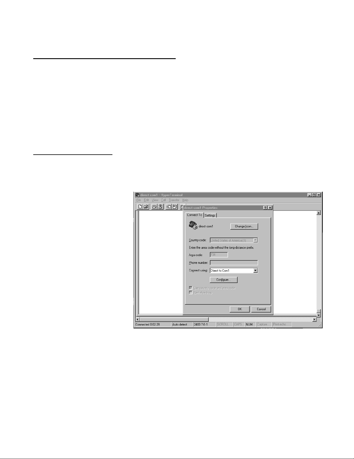
Once HyperTerminal™ is running
first select the COM port on your
computer. To do this click on
File on the menu bar and select
Properties. The Connection
properties window will open.
The most common choices are
either COM1 or COM2. Make
sure that there is no other
software running on the
computer that uses this COM
port.
In rare cases a program that uses a different COM port or an internal modem may even cause
problems with a free COM port. To be on the safe side, shut down all programs that use any serial
ports and/or modems before running HyperTerminal™.

..\Manuals\RCI-100-MDM rev.B.doc Page 8 of 16
Next click on the Configure button to bring up the Port
Settings window.
Set the Bits per second to 2400
Set the Data bits to 7
Set the Parity to Even
Set the Stop bits to 1
And choose None for Flow Control.
Click the OK button.
Now click the Settings tab near the top of the Properties
window to bring up the Settings window.
All settings here should be default settings and should not
require any changes.
Click on the ASCII Setup button to bring up the ASCII
Settings window.
Uncheck all check boxes. The Wrap lines… box is not
important and it may be checked or unchecked.
Click the OK button until you return back to the main
HyperTerminal™ screen.
..\Manuals\RCI-100-MDM rev.B.doc Page 9 of 16
File Capture using HyperTerminal™:
The RCI-100-MDM can send out its current configuration
data via the RS-232 serial port. To analyze and modify
this data it must be saved to a file on disk. This can be
accomplished by using the text capture feature of
HyperTerminal™. This feature takes all incoming serial
data and writes it to a file whose name is specified by the
user.
Click on Transfer and select Capture Text on the menu
bar. A new window will open up requesting the file name
where the data is to be saved to. Select an appropriate
directory with the Browse button and then type in a file
name where you want the data to be stored.
We suggest using file names like HOST.txt and REMOTE.txt for
easy distinguishing when it comes time to send the file back to
the RCI-100-MDM.
Click the Start button to begin the data capture.
Once all data has been received (see Downloading
Configuration Data below), the capture feature must be
turned off. To do this click on the Transfer menu item,
select Capture Text and click Stop on the fly-out window.
The file is now ready to be examined and modified by a
text-editing program such as Notepad™.
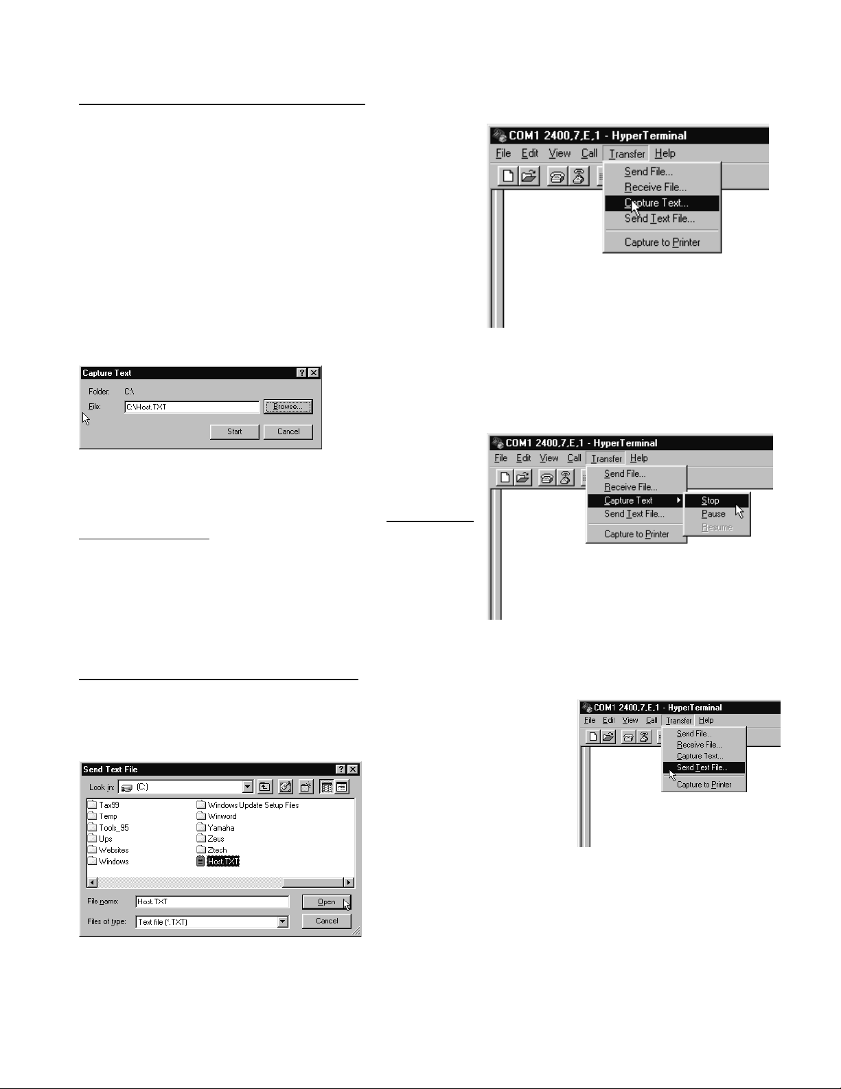
File Upload using HyperTerminal™:
To reconfigure the RCI-100-MDM the configuration data file must be
sent to it via the RS-232 serial port. To do this using HyperTerminal™
use the Send Text feature.
Click on Transfer and select
Capture Text on the menu
bar. A new window will
open up requesting the file
name that is to be sent.
Select an appropriate directory with the Browse button and
then select the file.
Click the Open button and the file will be sent through the
RS-232 serial port of your computer.
..\Manuals\RCI-100-MDM rev.B.doc Page 10 of 16
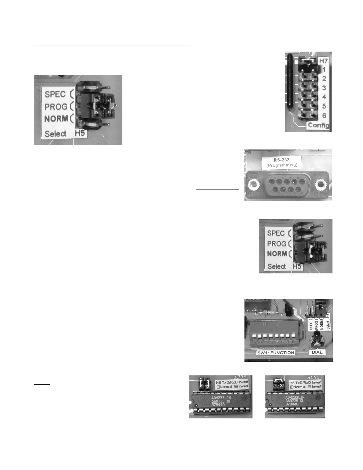
Downloading & Uploading Configuration Data:
To download the internal configuration data of the RCI-100-MDM or upload new
configuration data it must first be place in PROGRAMM mode.
1. Turn the power switch OFF.
2. Locate configuration jumper H7 on the modem
board and insert jumper H7-1 only.
3. Locate Communication Select jumper H5 on the
modem board and move the two jumpers from the
NORM position into the PROG position.
4. Connect the serial cable to the RS-232 connector on the modem
board and to your serial port on your computer.
5. Make sure you have your serial port software (see HyperTerminal
above) running on your computer.
6. Turn the power switch back on and wait at least 5 seconds.
You can now download and upload configuration data as may times as
necessary until the unit is configured properly. We suggest that you
download the configuration data again after you have uploaded it to make
sure that the RCI-100-MDM accepted it properly.
Upon completion turn the power switch OFF again, remove jumper H6-1,
move jumpers H5 back to the NORM position, disconnect the serial cable
and finally turn the power switch back on.
Download Configuration Data:
1. Make sure your serial software is ready to capture incoming serial
data (see File Capture using HyperTerminal above)
2. Press the DIAL button on the modem board.
3. The RCI-100-MDM will now send all of its internal configuration
data, which is being captured, to a file by the computer. The red TX
(transmit) LED will light or blink during this operation and you should
see the data on your screen. When the red TX LED stops flashing the download is complete.
Note: If you are not receiving any data on your
computer one possible reason may be that your
Transmit and Receive lines in the RS-232 cable
maybe crossed
Straight-Thru Cable
Null-Modem Cable

..\Manuals\RCI-100-MDM rev.B.doc Page 11 of 16
4. Stop the data capture on the serial port software.
You can now modify this file based on your requirements (see Configuration File Details below) and the
upload the file back to the RCI-100-MDM.
Uploading Configuration Data:
Make sure your configuration file has been carefully modified so that it is free of errors.
1. Follow the file upload procedure for your serial port software (see File Upload using
HyperTerminal™) to send the configuration file.
2. During the upload process you will see the green RX (receive) LED light or flash. Once the green
LED stops flashing the upload process is complete and the RCI-100-MDM will reply with one of two
messages:
CONFIG ERROR The configuration file was received incorrectly or it has an error
in it. Examine the file closely and/or try to re-send it.
SAVING CONFIGURATION The file was received correctly and is now being stored in the
RCI-100-MDM’s non-volatile memory. Wait for the RCI-100-
MDM to display the DONE message before moving on (this
should take about 5 seconds)
Configuration File Details:
The RCI-100-MDM configuration file is a human-readable text file that defines the various operating
parameters of the Answer-and-Originate Mode. The file is very simple in structure. Modifications can
be made easily with a text-editing program however care must be taken to adhere to a few constraints.
1. The first line of the configuration file must read $RCI-MDM. The ‘$’ is very important. During a
configuration file upload the ‘$’ tell the RCI-100-MDM that a configuration file is being sent.
2. Any line starting with a semi-colon ‘;’ is considered a comment line. There may be unlimited
numbers of these lines in the configuration file. This is useful to make notes about the
parameters to the user. These comment lines are not stored in the RCI-100-MDM!
3. The sequence of parameters may NOT be changed in any way.
4. The length of parameters must be exactly as present. If a parameter consists of 5 digits you
must pad it with leading zero’s to make it 5 digits long. Single digit parameters may only be one
digit. Be careful not to add any spaces at the end of the numbers!
5. Phone numbers are exempt from constraint 4. They may be any length up to 15 characters.
Following is the default configuration file of an RCI-100-MDM as it is shipped from the factory. Note the
large header at the top consisting of comment lines (starting with ; ). This is a brief explanation of all
the parameters and serves as a quick reference for a user who doesn’t have access to this manual
while performing a configuration.

..\Manuals\RCI-100-MDM rev.B.doc Page 12 of 16
Above is the header portion of the configuration file. It serves as a quick reference and it is sent out by
the RCI-100-MDM every time the configuration data is downloaded. It immediately precedes the actual
configuration data.

..\Manuals\RCI-100-MDM rev.B.doc Page 13 of 16
Above is the parameter portion of the configuration file. This is where changes can be made using a
text-editing program.

..\Manuals\RCI-100-MDM rev.B.doc Page 14 of 16
Configuration Parameters:
[I/O CONFIGURATION]
MODE This defines if the unit is a host or a remote. If it is a remote it further
identifies the remote address. This is especially important in multi-remote
systems.
Allowable values: 0 = Host, 1 thru 8 = Remote1 thru Remote8
REMOTES Number of remotes in the system. In a multi-remote system, this tells the
host how many remotes it has to call when it initiates a call.
Allowable values: 1 thru 8
CHANNELS ON REMOTEx Number of channels to be used on this remote. Total channels of
all remotes in a multi-remote system must not exceed HOST CHANNELS.
x=1..8
Allowable values: 1 thru 8
CHANNELS ON HOST Number of channels to be used on the host. All channels of all remotes
in any system must add up to the number of channels on the host.
Allowable values: 1 thru 8
[ANSWER]
RINGS The number of rings before the unit answers an incoming call.
Allowable values: 0 = never answer a call, 1 thru 9 = rings before answer
[DIAL]
AUTODIAL The auto-dial time interval in minutes. If this parameter is set to 00000 then
the unit will NOT automatically initiate a call and will call only when a DI or AI
status changes (see below). If this parameter is set to a value greater than
00000 then the unit will place a call automatically in this time interval.
Allowable values: 00000 = no auto-dial, 00001-65535 auto-dial interval (min.)
REDIAL Number of times the unit will attempt a re-dial if the previous dial failed to
establish a connection (because of busy signal, reorder signal, etc.). If the
unit does not establish a connection after the set number of redials it stops
the re-dial procedure. New events that will require a call to be placed will re-
initiate the dialing procedure.
Allowable values: 0 = re-dial until successful, 1 thru 9 number of re-dials
PAUSE Time interval, in seconds, the unit waits between re-dials. To prevent
ongoing contention between units it is recommended that every unit in a
system be assigned a different PAUSE interval. That way if two units happen
to call at the same time, they wait different intervals before re-dialing.
Allowable values: 00010-00255 = re-dial interval in seconds (note the 10
second minimum)
TIMEOUT Time interval, in seconds, to wait for called unit to answer. If the called unit
does not answer in this time, the call is considered unsuccessful.
Other manuals for RCI-100 Series
1
This manual suits for next models
1
Table of contents
Other Pribusin Recording Equipment manuals


Popular Recording Equipment manuals by other brands


Sennheiser
Sennheiser EW 300 IEM G3 - 01-09 instruction manual

PMFoundations
PMFoundations ER-808 Assembly guide

Sound Devices
Sound Devices 702 User guide and technical information

Tektronix
Tektronix MTX100A user manual

Bunker Hill Security
Bunker Hill Security Power drive BPD-1 user guide

Auralex Acoustics
Auralex Acoustics Project 2 user guide