Samsung Electronics 2-3
2-2 Product Specifications
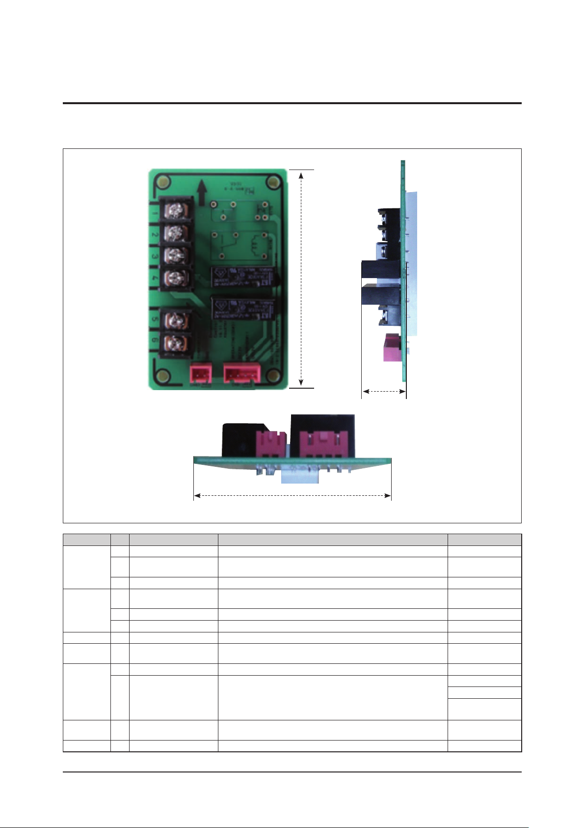
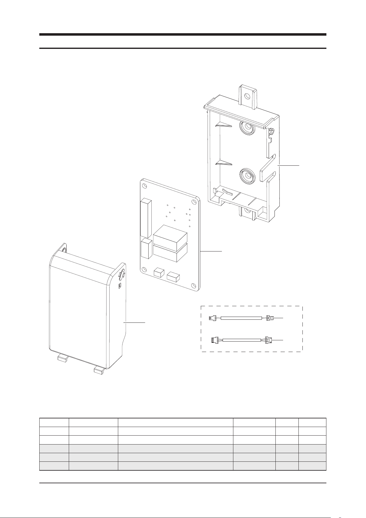
2-2-1 Appearance Dimensions
(Unit : mm)
Division No Item Specifications Remarks
General
Conditions
1 Area of use Europe, Turkey
2 Usage type External Contact Interface Module.
(ex. Perform refrigerant leakage Interface Module function)
Refer to installation
manual.
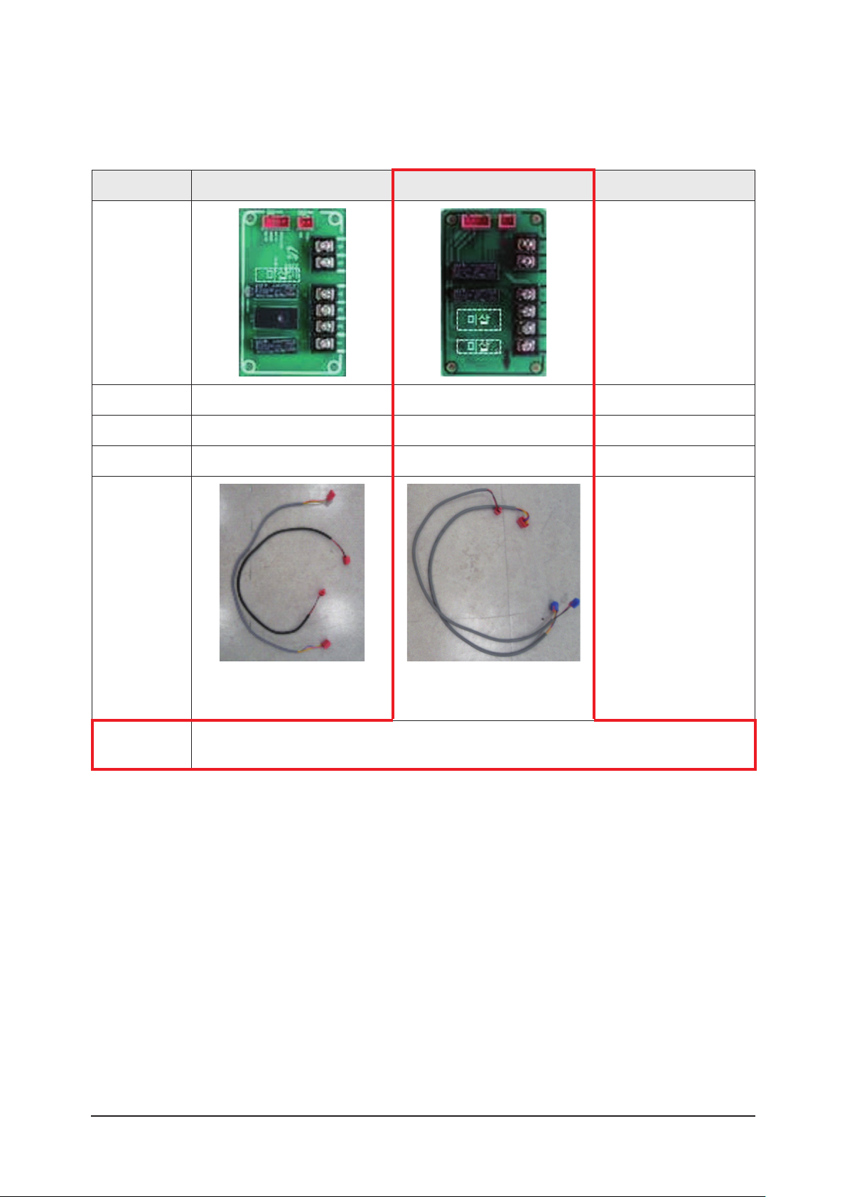
3 Supplying parts Contact the service center.
Installation
Conditions
1Standard temperature,
humidity 15~20˚C, 35~65%
2 Operating temperature 0˚C~40˚C (Indoor)
3 Operating humidity 30%RH~90%RH (However, conditions without condensation)
Power 1 Input 12VDC/0.1A
Installation
Conditions 1 Installation place Outdoor C-BOX Interface Module mounting place or suitable
location.
Delivery
1 Opening Follow the prescribed sequence.
2 Delivery confirmation
Confirm by delivery check sheet and repair defective item.
Instructions for use, conditions of use and precautions for use shall
be made in the method prescribed in the user manual.
If problem occurs in the above process, repair it where service is
available.
How to
install 1 Refer to installation manual.
Etc 1 Refer to installation manual necessarily.
80
16.6
50