Landustrie DCP22 Manual

Landustrie versie 01-21 | Operation & maintenance manual DCP22
Subject to modifications
1 / 16
Operation & Maintenance Manual
Submersible pumps type DCP22
Landustrie Sneek BV Tel. +31 515-486888
Pieter Zeemanstraat 6 Fax +31 515-412398
8600 AD Sneek, Holland www.landustrie.nl

Landustrie versie 01-21 | Operation & maintenance manual DCP22
Subject to modifications
2 / 16
Contents:
Foreword:.........................................................................................................................3
Pump identification:........................................................................................................3
Power supply:..................................................................................................................3
Usage limitations:............................................................................................................3
General safety instructions before installation or maintenance:................................4
Environment: ...................................................................................................................4
Installations: ....................................................................................................................5
Noise level:.......................................................................................................................6
Hoisting device:...............................................................................................................6
Hoisting cable:.................................................................................................................6
Spare parts:......................................................................................................................6
Starting up: ......................................................................................................................7
Electrical pump start options:........................................................................................7
Cable connection direct start of the pump (DOL).........................................................8
Cable connections star-delta start of the pump (YD)...................................................9
Checkpoint first pump start:.........................................................................................10
Maintenance:..................................................................................................................10
Adjustment of the cutting mechanism: .......................................................................12
EC Declaration of conformity:......................................................................................13
Service Contract:...........................................................................................................13
Verhelpen van storingen:..............................................................................................13
Trouble shooting:..........................................................................................................14

Landustrie versie 01-21 | Operation & maintenance manual DCP22
Subject to modifications
3 / 16
Foreword:
This manual includes several warnings, installation guidelines and safety instructions. Before
installation, please read carefully to avoid dangerous situations, which can lead to severe
physical injury, and which could also damage the pump.
The DCP pump series are typically designed to pump lightly contaminated wastewater.
The pumps are equipped with a heavy duty Epoxy coating for long operational use.
The DTP pumps are designed for professional use only.
Only trained and skilled personal may install, maintain and operate the pump.
Pump identification:
The main characteristics are given on the data plate, which is connected to the pump.
Power supply:
The power supply of the pump is part of the controls of the electrical installation.
Please read carefully the specific user instructions of the electrical installation.
These instructions, including the wiring diagram, are necessary for safe installation.
Usage limitations:
The DCP22 pumps are developed for normally contaminated municipal waste water.
The pumps in Basic Version may not be installed in potential explosive atmospheres
Bj.
Data plate DTP
Basic version
n
In
P
Type
No.
Legenda:
Type
=
Pump type
m3/h
=
Capacity in duty point
~
=
Number of phases
Code
=
Product code
m
=
Head in duty point
Hz
=
Frequency
No.
=
Serial number
rpm
=
Speed
Y of D
=
Connection (star or delta)
Yr
=
Year of production
P1
=
Rated electrical power
V
=
Voltage
kg
=
Weight [kg]
P2
=
Shaft power
A
=
Max. current
Ø
=
Impeller diameter
cos phi
=
Power factor
Cert. no.
=
For ATEX pumps only
D 400V 3.6A
Y 690V 2.1A

Landustrie versie 01-21 | Operation & maintenance manual DCP22
Subject to modifications
4 / 16
General safety instructions before installation or maintenance:
The following safety instructions should be followed up very carefully to avoid severe
injury or damage.
Before maintenance or inspection, both mechanical and electrical, always switch off the
pump.
Turn off the main power supply, log out and tag out according local procedures!
Remove the fuses (if applied) and store them in a safe place.
Switch off the emergency power supply if available.
Alert other people with a clear warning to make aware of this service or maintenance
operation.
For servicing the pump, and replacing the oil to bring the pump in horizontal position.
This position is also needed to check the rotation of the pump.
Be aware the recoil can be very powerful, don’t go near rotating parts, or stand close
to the pump when testing.
Never put your hand into the pump if no safety measures are taken!
When it is necessary to inspect the pump outside the sump, please close the cover
of the pump sump, and take care about the following:
Check carefully the power cable for bends and jamming.
To avoid cable damage put a decent spacer between pump cover and the sump
Never use the power cable to hoist the pump!
Avoid any risk, that might damage the power supply cable.
Always use safety shoes and safety gloves when handling the pump.
Make sure all safety measures are conform the legal laws and provisions,
such as the specific Labor Safety Instructions for confined spaces.
Environment:
Parts which will be replaced during repair, maintenance or renewal, could contain
materials which could be harmful to the environment.
Please be also aware that some of the components can be very useful for reuse.
The owner is responsible for careful disposal and processing of the materials.
Do this in according to the local environmental regulations.

Landustrie versie 01-21 | Operation & maintenance manual DCP22
Subject to modifications
5 / 16
Installations:
For the DTP pumps in basic versions several installation options are possible.
These options will be explained, with focus on specific points of attention.
Installation “BWK”
This installation represents a permanent submerged installation using the header coupling” type
“BWK”.
The pumps are suspended in horizontal position to the coupling.
Points of attention:
Ensure a good free passage under the pump, at least identical
to the suction opening.
Adjust start- and stop levels in such a way that the motor
will not make more than 20 starts per hour.
Check that the motor is adequately cooled.
At full load conditions, at least 2/3 of the motor housing should
be submerged.
The pump casing must stay under water to avoid air being
drawn in.
Installation “OWK”
This installation represents a permanent submerged installation using the guide bar coupling”
type “OWK050”
Points of attention:
Ensure a good free passage under the pump, at least identical
to the suction opening.
Check both the vertical and parallel position of the guide bars.
The maximum tolerance for the vertical position is ± 3o.
The installation angle for the pump in case of installation or
taking out is important.
This angle (between pump and guide bar) is about 0oand 5o.
This angle can be adjusted by changing the position of the
hoisting cable.
Adjust start- and stop levels in such a way that the motor will
not make more than 20 starts per hour.
Check that the motor is adequately cooled.
At full load conditions, at least 2/3 of the motor housing should be submerged.
The pump casing must stay under water to avoid air being drawn in.

Landustrie versie 01-21 | Operation & maintenance manual DCP22
Subject to modifications
6 / 16
Installation “VRS”
This installation represents freestanding submerged installation.
Points of attention:
Ensure a good free passage under the pump, at least
identical to the suction opening.
Adjust start- and stop levels in such a way that the motor
will not make more than 20 starts per hour.
Check that the motor is adequately cooled.
At full load conditions, at least 2/3 of the motor housing should
be submerged.
The pump casing must stay under water to avoid air being drawn in.
Noise level:
Pump installations in sumps, with closed cover, the noise level will not exceed 70 dB(A).
Hoisting device:
Submersible pumps can be hoisted out of the sump by means of an
adequate lifting device. Landustrie is able to deliver this certified equipment.
Hoisting cable:
If applied, please replace the stainless steel hoisting cable every two years, or
accordingly to local regulations.
Spare parts:
When ordering spare parts, please specify the following data:
Pump type, product code and the serial number.
This information is available on the data plate of the pump.
For ordering spare parts please contact your supplier.
Parts list and sectional drawings are available on request.

Landustrie versie 01-21 | Operation & maintenance manual DCP22
Subject to modifications
7 / 16
Starting up:
Rotation control:
The correct direction of rotation is counter clockwise
(ccw), looking at the suction opening of the pump (see
picture).
Check procedure:
Place the pump into horizontal position, start the pump short time,
check visually the direction of rotation,
Please follow all safety measures!.
The correct direction of rotation can also be checked by observing
the recoil of the pump during start up.
Looking at the motor the recoil should be counter clockwise (ccw)
Minimum water level:
The pump should operate with sufficient cooling.
This means that at least ⅔ of the motor is submerged.
Reducing this minimum level means the motor runtime is limited to a maximum of 15 minutes, to
avoid overheating. The cooling down time is at least twice the running time.
Electrical pump start options:
The different connections for the cables are specified on page 8 and 9.
Check the cable type, installed on the pump and verify the data onto the pump data plate.
Check if the pump is equipped with extra leads for thermal protection and/or water in oil
detection.
We do strongly recommend to connect the pump to the mains by authorized personal only.
Please ensure this is done accordingly and in compliance with local regulations.

Landustrie versie 01-21 | Operation & maintenance manual DCP22
Subject to modifications
8 / 16
Cable connection direct start of the pump (DOL)
Without klixons and/ or water in oil detection
1x 4 core cable
Motor in delta Motor in star
Including klixons and/or water in oil detection
1x 7 core cable
Motor in delta Motor in star
GN/YE Green/Yellow
T1, T2 Klixons
(or thermistors)
WA Water in oil
detection
L1,L2,L3 3 phase line
BN Bruin
GR Grijs
BK Zwart
GN/YE Groen/Geel
L1,L2,L3 3 fasen net
BN Brown
GR Grey
BK Black
GN/YE Green/Yellow
L1,L2,L3 3 phase line

Landustrie versie 01-21 | Operation & maintenance manual DCP22
Subject to modifications
9 / 16
Cable connections star-delta start of the pump (YD)
Without klixons and/or water in oil detection
1x 7 core kabel
With klixons and or water in oil detection
1x 10 core cable
GN/YE Green/yellow
L1,L2,L3 3 phase line

Landustrie versie 01-21 | Operation & maintenance manual DCP22
Subject to modifications
10 / 16
Checkpoint first pump start:
Before installing and start operating the pump following checkpoints are involved:
Check on delivery
Remove the pump from the packing and check for transport damage, such as material
errors, cracks of bended cable.
Check for completeness of the delivery.
If the delivery is incomplete, or damaged, please contact your supplier immediately.
Check oil level
Verify the oil level in the seal housing (according to procedures on page 12)
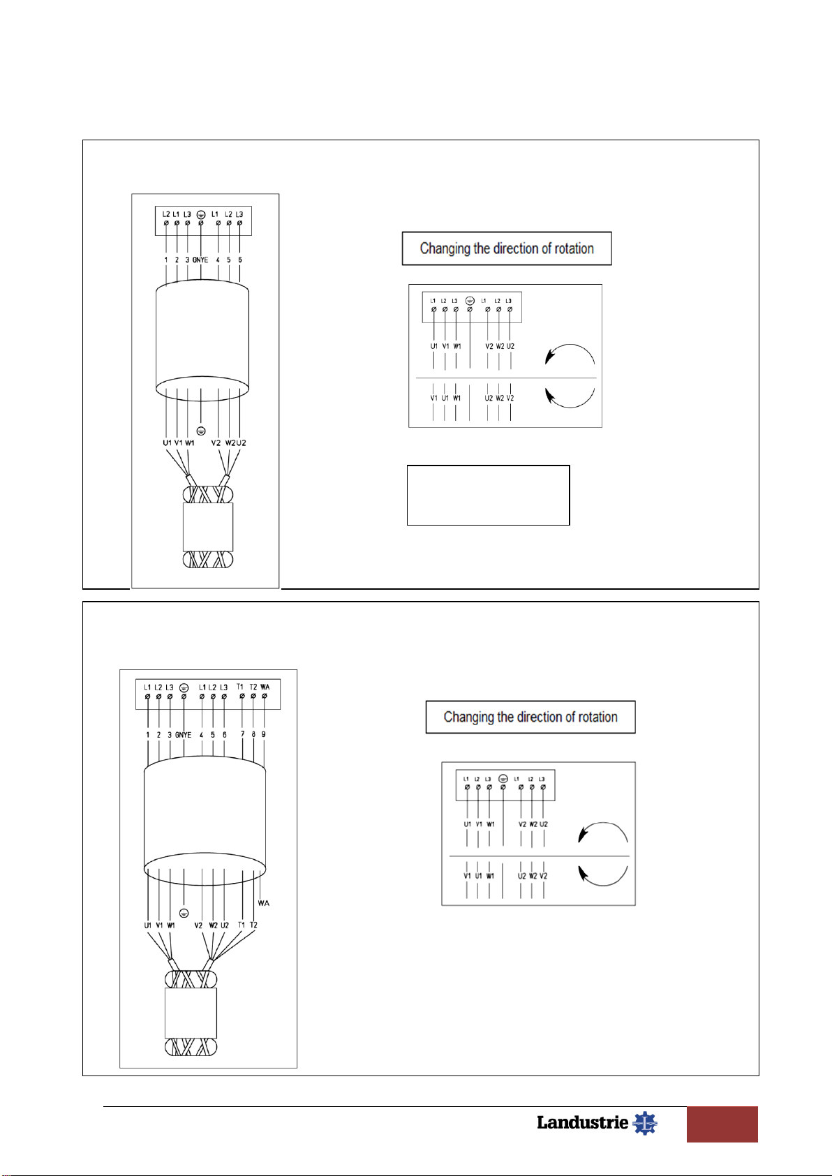
Check Power supply.
Verify if voltage, frequency and starting method are according to the data as specified on
the pump data plate.
Connect the pump according to the wiring diagram of the electrical cabinet.
Information about the pump cable codes can be find on page 8, 9 or 10.
Thermal protection (klixons)
Check the pump for the presence of thermal protection, the connection values for the
standard thermal protection are max. 250V-1.6A. In ‘cold’ condition the switch is closed.
Thermistors (PTC), if thermistors are supplied: Resistance cold: 200-500 Ohm
Resistance at switching temperature: 1650-4000 Ohm.
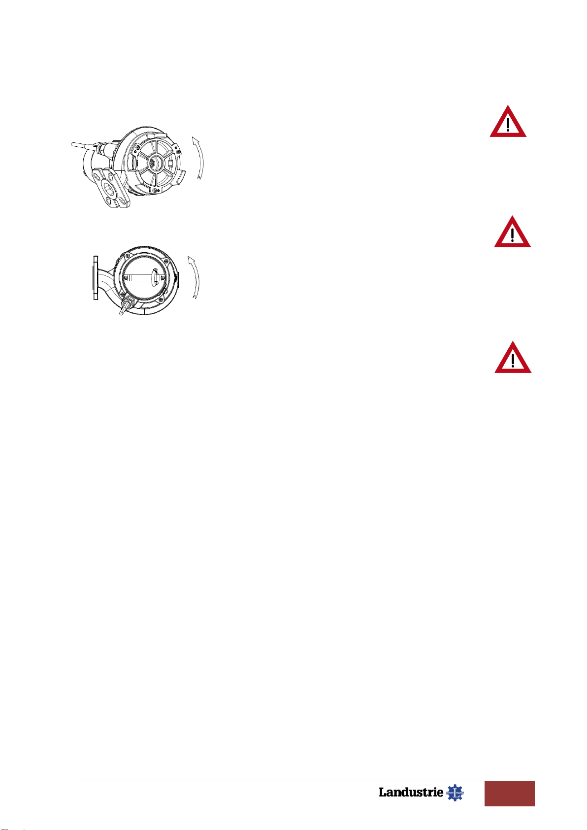
Cable entry
Especially when the pump has been stored for a long time. Turn the cable entry, if
necessary to tighten the rubber gland of the cable entry.
Motor protection
Verify the presence of the motor protection circuit breaker.
At direct start (DOL) the motor circuit breaker should be set at the current value given on
the data plate of the pump.
At star delta start (YD) the setting of the motor circuit breaker should be 0.6 of the current
value on the data plate of the pump.
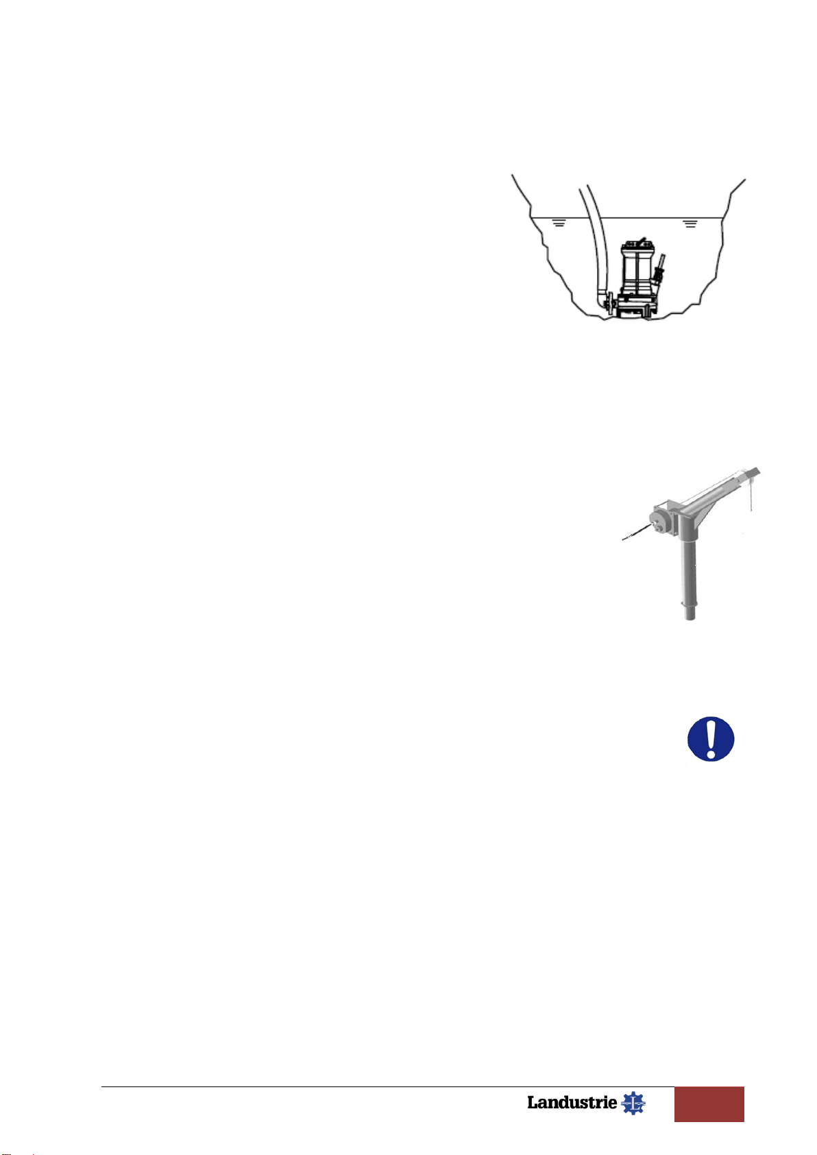
Maintenance:
Before taking out the pump from the installation, please switch of the mains, according to the
instructions on page 4.
Clean the pump adequately!
Take care! The surface of the pump can be hot, especially when is just switched off.
Maintenance schedule:
After the first 100 operating hours; Check the condition of the oil.
If too much water is mixed with the oil, please contact your supplier.
Every 1000 operating hours or each year; - Check both the condition of the oil and the oil
level. If too much water is included, please contact your supplier.
Change the oil if not transparent.
Lubricants:
The bearings of the pump are greased for life.
Standard oil type for the mechanical seals: Shell Tellus 32, viscosity 32 cSt.
Onderhoud schema

Landustrie versie 01-21 | Operation & maintenance manual DCP22
Subject to modifications
11 / 16
Cable entry: If the pump is stored for long time, the elasticity of the
rubber gland might be diminished.
This can lead to leakage to the motor compartment.
By turning-in the cable entry clockwise, the sealing of the
gland will be secured.
Unscrew the 2 hexagon socket screws (1).
Remove the cable clamp (2).
Turn the hexagon head of the entry (3) clockwise, using
A proper tool, so far that it is possible to place the
cable clamp again.
Screw-in the 2 hexagon socket screws (1).
It is possible that your pump is equipped with an entry without
a clamp. This depends on the used cable.
Motor housing: Unscrew the inspection plug of the motor housing (1).
Put the pump in horizontal position with the inspection
opening downwards.
If water is present this will come out this way.
A small amount of water, due to condensation, is
permissible.
More water is an indication of leakage of
the construction. Oil is an indication of
seal failure between motor housing and oil
chamber. If so, contact your dealer.
Oil level:
Put the pump in a horizontal position so that the
2 hexagonal socket screws are on top.
Unscrew the level plug (1) and the vent plug (2).
The oil level should be at the lower side of the openings.
By turning the pump a bit this should be visible.
If not so fill up to the right level.
The drain plug (3) is located at the bottom side.
Always use the right kind of oil !

Landustrie versie 01-21 | Operation & maintenance manual DCP22
Subject to modifications
12 / 16
Adjustment of the cutting mechanism:
If for inspection or renewal suction cover is removed,re-assembling must take place in
the next sequence:
Turn back the three adjusting screws (2) into the suction
cover.
Put the suction cover in the pump casing, and push it down
until it touches the impeller vanes.
Fasten the three connecting bolts (1) by hand and unscrew
them half a turn.
Fasten the three adjusting screws (2) , to fix the suction
cover.
Check that the impeller can rotate without much force.
If necessary, re-adjust the mounting and adjusting screws.
The play between the impeller and the suction cover has to be about 0,6 mm.
Now the pump is operational again.

Landustrie versie 01-21 | Operation & maintenance manual DCP22
Subject to modifications
13 / 16
EC Declaration of conformity:
Service Contract:
Although the quality standards of the Landustrie pumps are very high, we do strongly recommend
to close a service contract with your local supplier.
For service- or technical information, please contact:
Verhelpen van storingen:

Landustrie versie 01-21 | Operation & maintenance manual DCP22
Subject to modifications
14 / 16
Trouble shooting:

Landustrie versie 01-21 | Operation & maintenance manual DCP22
Subject to modifications
15 / 16

Landustrie versie 01-21 | Operation & maintenance manual DCP22
Subject to modifications
16 / 16
Table of contents
Other Landustrie Water Pump manuals
Popular Water Pump manuals by other brands

Intex
Intex Quick-Fill AP639 owner's manual

STAR Water Systems
STAR Water Systems COND-1 installation instructions

Pfeiffer Vacuum
Pfeiffer Vacuum HILOBE 8103 operating instructions

EINHELL Bavaria
EINHELL Bavaria BPW 48 operating instructions

Flotec
Flotec FP5010 owner's manual

Festool
Festool VAC SYS VP Original operating manual/spare parts list

HSR
HSR PDB040-G operating instructions

Sykes
Sykes Yakka 150 manual

Time Electronics
Time Electronics 7195 user manual

Crane
Crane Deming 5260 Series Installation, operation & maintenance manual

ULTIMATE SPEED
ULTIMATE SPEED 12 V UOP 12 C1 Operation and safety notes

Bühler technologies
Bühler technologies P1.1 Brief instructions