LARTET DN-107NN Series User manual

1227K34A
OPERATION MANUAL
OF THE
DN-107NN DISPLAYS

INDEX
1. INTRODUCTION.................................................................................................................... 3
1. GENERAL CHARACTERISTICS.............................................................................................. 4
1.1. Electrical characteristics of the displays.............................................................................4
1.1.1. Electrical characteristics of the dn-107 displays.......................................................... 4
1.2. Dimensions and fixation of the displays .............................................................................5
1.2.1. Dimensions of DN-107/3 displays................................................................................5
1.1.1. Dimensions of DN-107/4 displays................................................................................5
1.2.2. Fixing DN-107 displays................................................................................................ 6
2. INSTALLATION......................................................................................................................... 7
2.1. Power supply ......................................................................................................................7
2.2. Profinet line connection ......................................................................................................8
3. OPERATION.............................................................................................................................. 9
3.1. Initial commissioning...........................................................................................................9
3.2. Programming parameters................................................................................................... 9
4.2.1 Access to parameter settings...................................................................................... 10
4.2.2 Access to parameter settings...................................................................................... 11
5. PROTOCOL AND OPERATION OF WORK........................................................................... 14
5.1 PROFINET Protocol ..........................................................................................................15
5.1.1 Before the configuration..............................................................................................15
5.1.2 Downloading the GSD file...........................................................................................16
5.1.3 Generating a cutom GSD file...................................................................................... 16
5.1.4 Installing the display in TIA Portal V13 .......................................................................19
5.2 Work operation...............................................................................................................22

1227K34A
1. INTRODUCTION
The numerical displays of the DN-107NN series are industrial displays that are controlled
by the PROFINET protocol.
The selection of the parameters and the communication protocol is done by means of a
pair of pushbuttons with an easy-to-program code system.
The height of the digits, of 57mm, which allows a reading distance of up to 30m, is one
of the main features.
The field of application of these visualizers is very wide in applications where it is required
to display numerical values resulting from industrial processes sent from a PLC/PC by PROFINET
communication.
PROFINET
PROFINET
Display
PC PROFINET
Supervisor
PLC
IO-Controller
Fig. 1 Profinet Communication

1. GENERAL CHARACTERISTICS
1.1. Electrical characteristics of the displays
1.1.1. Electrical characteristics of the dn-107 displays
Supply voltage......................................100 to 240 VAC 50/60Hz. Option 24VDC.
Consumption ........................................See section 2.2
Display...................................................7 segments of 57mm height + decimal point.
................................................................Red LED. Reading distance 30 meters.
Parameter memory...............................Eeprom.
Communication protocol.....................Profinet RT class 1 v2.3
Environmental conditions ...................Working temperature: -20 to 60ºC.
................................................................Storage temperature: -30ºC to 70ºC.
................................................................Humidity: 20-9 0% RH non-condensing.
................................................................Maximum ambient illumination: 1000 lux.
................................................................Protection: IP41.

1227K34A
1.2. Dimensions and fixation of the displays
1.2.1. Dimensions of DN-107/3 displays
120
70
40
All measurements are in millimeters
1.1.1. Dimensions of DN-107/4 displays
245
120
70
40
All measurements are in millimeters

1.2.2. Fixing DN-107 displays
100
150/400/600
90 º
73,5
7
15
52
52
All measurements are in millimeters
Fixing plate
M8

1227K34A
2. INSTALLATION
The installation of the DN-107NN is not particularly delicate, but some important
considerations must be considered.
They should not be anchored in places subject to vibration, nor in places that generally
exceed the limits specified in the characteristics of the display, both in temperature and humidity.
The degree of protection of the DN-107NN displays is IP41, which means that it is
protected against the penetration of foreign solid objects of a diameter greater than 1 mm, and
against the vertical fall of water droplets.
DN-107NN displays should not be installed in places where the lighting level exceeds
1000 lux. Nor should the direct incidence of the sun's rays on the display be allowed because we
would lose visibility.
In the electrical installation, proximity to lines circulating very high intensities, high voltage
lines, as well as high frequency generators and U/F converters for motors should be avoided.
2.1. Power supply
The power supply can be from 100 to 240VAC, 50/60Hz or in option at 24VDC.
The section of the power conductors will be according to consumption, the ground
conductor (GND) will be a minimum section of 1.5 mm².
The 220V power connector has 4 contacts and is in the inner part of the equipment. It is
accessed by removing the top cover. Connect the power cords according to the diagram below.
The 24V power connector has 5 contacts and is in the lower part of the equipment. It is
accessed by removing the top cover. Connect the power cords according to the diagram below.

2.2. Profinet line connection
The connection of the Profinet line in the DN-107/NN displays is carried out by means of
the RJ-45 connector located on the inside of the equipment.
To access the inside, we will open the top cover of the visualizer.
The display incorporates a module with 2 Profinet connectors.
For the connection between the display and the control device (PC/PLC), it is
recommended:
1. Direct cable (100Base-T4, CAT 5E) if the connection is made through a Switch/Hub
2. Crossover cable of identical characteristics if connected directly to the control device
Profinet
Power supply
connector
To connect several displays, the internal ports of the Profinet module of the visualizer can
be used (incorporates 2 ports).
PROFINET

1227K34A
3. OPERATION
3.1. Initial commissioning
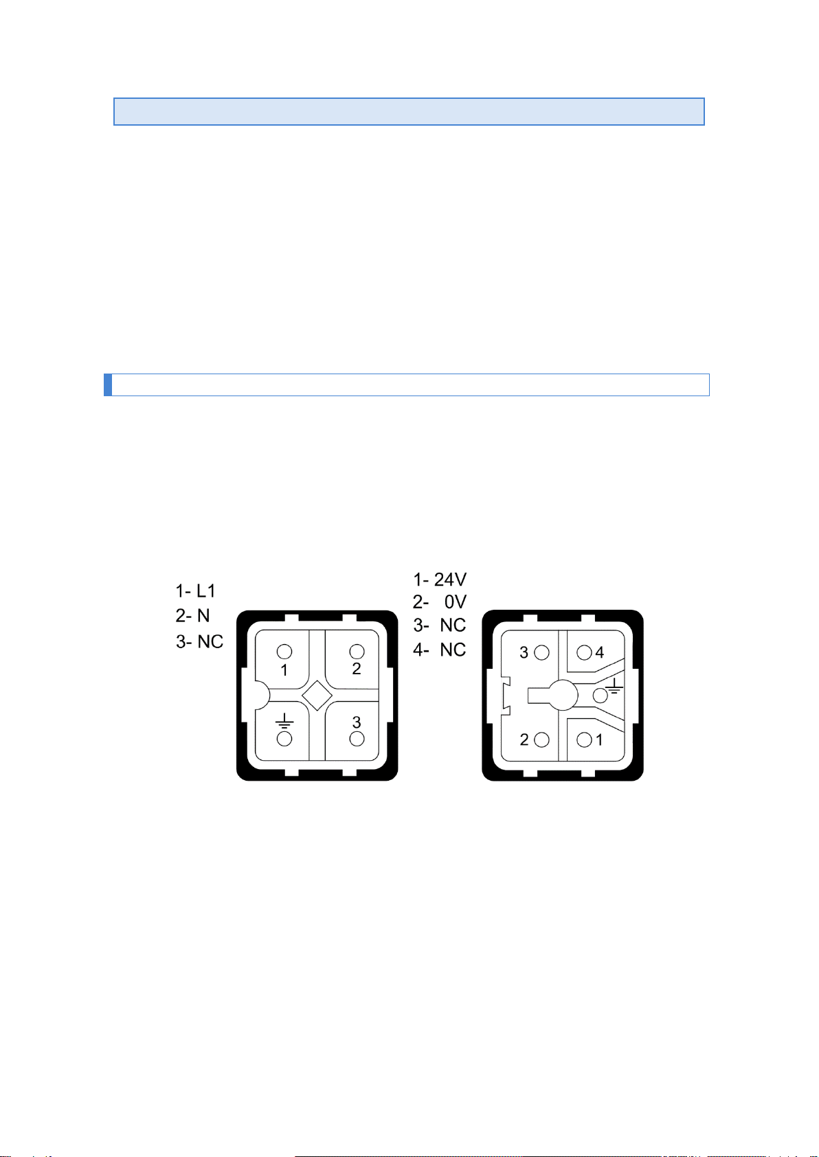
Before connecting the visualizer to the network, we must make sure that all connections
have been made correctly and that the visualizer is firmly placed.
Each time we connect the visualizer to the Power Network, an initial Reset occurs with a
test of all the segments that make up the visualizer. The test consists of the sequential illumination
of all digits with the value "8", all digits with value "0", all illuminated decimal points and finally the
version code. From this point three situations can occur:
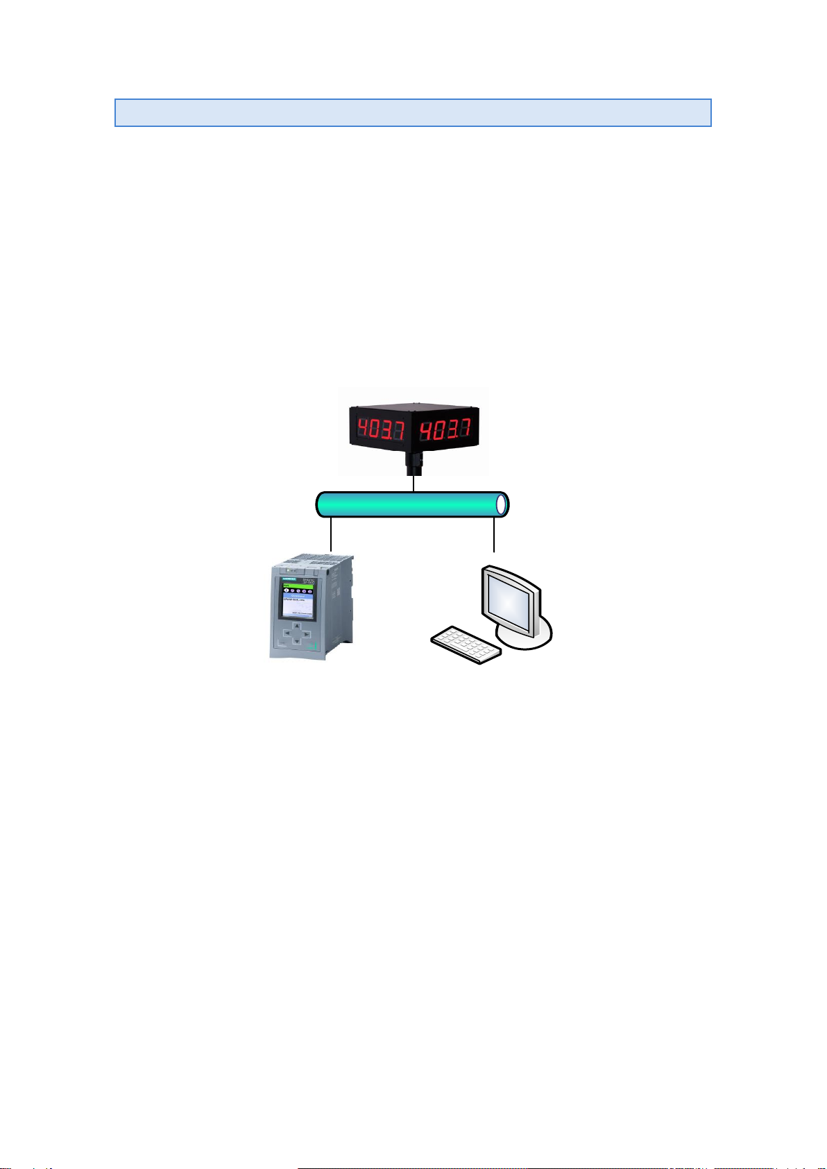
a) The viewer receives data over the Profinet network and displays it.
b) The viewer receives no data and the time without data is equal to zero (see section
4.2.2.3). Continues to display the Firmware version.
c) The viewer receives no data and the time without data is non-zero. After time without
data shows a hyphen in each digit.
3.2. Programming parameters
Before proceeding to use the visualizer, the configuration parameters must be
programmed, to parameterize the equipment according to the numerical values that we want to
represent.
The configuration of the parameters is done through a menu that is selected by two
buttons located on the inside of the display. The field that can be modified is displayed in blink.
The parameters that can be configured are:
1- Numeric data type (Float, UFloat, WORD, UWORD, ASCII)
2- Communication protocol (if the computer is multiprotocol)
3- Time without receiving data
B, C, D, E, nr, r1, r2 y r3- Only for viewers with color option.
F- To exit modifying parameters.
For the programming of the parameters, the three digits on the right of the viewer are
used. The third digit on the right, which is identified by having the decimal point enabled, indicates
the number of the parameter and the two digits on the right the value of the parameter. The digit
that is in flicker is the one that can be modified.

4.2.1 Access to parameter settings
To enter the sequence of modifying parameters, you must press and hold, the forward
key "*" for three seconds. After this time, the first parameter is displayed.
From this moment there are two options:
1- Modify the value of the parameter.
•By pressing “”forward key, you can select values and the parameter number
correspondingly.
•Press “”again to return to display the parameter number.
•To increase the value of the parameter, press the “+” key. That increases the
value of the selected digit until it reaches the maximum value the next press goes
to the minimum value.
If the parameter entered is incompatible with the computer, that parameter
will not be accepted. For example, our equipment has a parameter code for each
protocol ("2" ISO 1745, "3" ModBus ... "10" Profinet, etc). In a DN-NN family viewer
that in this version can only work in Profinet, it will not accept any parameter other
than "10".
2- Select another parameter.
To select another parameter, you must flash the parameter name using the "" key and
then select the new parameter using the "+" key. The parameter number is the third digit starting
from the right.
To exit the sequence of modifying parameters you must select the parameter F and then
press "".

1227K34A
4.2.2 Access to parameter settings
4.2.2.1 Parameter 1: Numeric data type
Allows you to select whether to work with numeric values in text format (ASCII) or with
Float or Word data types (with or without sign)
If the parameter entered is zero, the minimum value of this table will be saved. If the
value entered is greater than the allowed value, the maximum value of this table will be
saved.
4.2.2.2 Parameter 2: Communication protocol
The communication protocol is configured. The current version of the DN-NN family only
allows you to work with the Profinet protocol.
If the parameter entered is incompatible with the computer, that parameter will not
be accepted. For example, our equipment has a parameter code for each protocol ("2" ISO
1745, "3" ModBus... "10" Profinet, etc). This release will not accept any parameter other
than the one specified.
4.2.2.3 Parameter 3: Time without receiving data
This parameter allows you to schedule a time to warn that no data is being received. The
warning occurs if the scheduled time is exceeded. Every time a piece of data is received, time is
zeroed. The code "00" (No time) does not produce any warnings.
To indicate that the time has been exceeded, a hyphen is displayed in each digit.
Code
Time
Code
Time
00
No time
11
1 min.
01
2 s
12
2 min.
02
4 s
13
5 min.
03
6 s
14
10 min.
04
8 s
15
20 min.
05
10 s
16
40 min.
06
14 s
17
1 hour.
07
20 s
18
2 hours.
08
26 s
19
5 hours.
09
30 s
20
10 hours.
10
40 s
21
25 hours.
Parameter
Type
Numerical range
01
Float
-2147483648 to 2147483647
02
UFloat
0 to 4294967295
03
Word
-32768 to 32767
04
UWord
0 to 65535
05
ASCII
1 numeric character/digit
(Maximum 10 characters)
Parameter
Protocol
10
Profinet

4.2.2.4 Parameter 4: Parameters B, C, D, E (Color option)
The color option allows you to automatically modify the color of the digits according to the
current value. The possible colors are: Red, Green, and Yellow.
To be able to manage the color, 2 internal bits (r1 and r2) are used that are activated
depending on the value of the visualizer. To configure the activation levels of these bits,
2 parameters per internal bit are required, Parameters B, C configure the r1 and D bit, E
the R2 bit.
4.2.2.4.1 Parameter 4: Parameters B, C, D, E (Color option)
With the parameter B the form of activation and the delay or hysteresis are configured.
The C parameter sets the trigger level. The heavier digit allows you to set a negative
value.
Parameter B
Left digit
Control bit
Right digit
Activation
0
ON if Value > Parameter C
0
No delay or hysteresis
1
ON if Value < Parameter C
1
Delay 1s
2
Always OFF
2
Delay 2s
3
Delay 4s
4
Delay 6s
5
Delay 10s
6
Hysteresis = 2
7
Hysteresis = 4
8
Hysteresis = 8
9
Hysteresis = 12
4.2.2.4.2 Configuring the internal bit r2
With the D parameter, the form of activation and the delay or hysteresis are configured.
With the E parameter, the trigger level is configured. The heavier digit allows you to set a
negative value.
Parameter D
Left digit
Control bit
Right digit
Activation
0
ON if Value > Parameter E
0
No delay or hysteresis
1
ON if Value < Parameter E
1
Delay 1s
2
Siempre OFF
2
Delay 2s
3
Delay 4s
4
Delay 6s
5
Delay 10s
6
Hysteresis = 2
7
Hysteresis = 4
8
Hysteresis = 8
9
Hysteresis = 12

1227K34A
4.2.2.5 Parameters nr, r1, r2, r3 (Color option)
To define the color, the combination of the 2 internal bits (r1 and r2) is used.
The following parameters are used to define colors.
4.2.2.5.1 Use of a single color
To use a single color regardless of the value that is displayed, configure the following
parameters:
Parameter
Value
B
20
C
0
D
20
E
0
nr
color
r1
color
r2
color
r3
color
Parameters Cand Ecan have any value.
The parameters nr, r1, r2, and r3 must be assigned the same color.
Regardless of the color configured, red is used in the parameter programming.
4.2.2.6 Parameter F
To modify parameters. To exit modifying parameters, click the key (""). Before exiting,
the parameters are saved.
If you want to continue modifying parameters, press the "+" key until you reach the
parameter you want to modify.
Color if no internal bit is enabled. To change the color, press the *
key. Pressing + moves to the next parameter.
Color if r1 is enabled. To change the color, press the * key.
Pressing + moves to the next parameter.
Color if r2 is enabled. To change the color, press the * key.
Pressing + moves to the next parameter.
Color if both r1 and r2 are activated. To change the color, press
the * key. Pressing + moves to the next parameter.

5. PROTOCOL AND OPERATION OF WORK
This section will deal with the PROFINET protocol, as well as communication with the
visualizers through this protocol.
The numerical value notation used in this manual is as follows:
•When we treat a hexadecimal number, the number will be written followed by "h".
•When we treat a decimal number, the number will be written followed by "d".
•When we treat a binary number, the number will be written followed by "b".
•When we treat a number in ASCII, it will be described as such.
For example: the character X ASCII, can be seen as 58h, 88d or 1011000b, as needed
to be described at the time. The number 15 ASCII can be described as 31h 35h, 49d 53d
or 110001d 110101d depending on the context.
Definitions of words used in the description of this chapter:
Offline: Parameterization to be performed on the visualizer, through the configuration
options of the equipment itself or configuration software applications, prior to the installation or
network operation of the visualizer.
Online: Configuration change that can be made with the computer running on a network.
XXX or xxx: Sequences of 'X' are used to indicate characters that can be variable, such
as versions or dates.
< >: Among these signs is an option that the user must particularize according to the
equipment purchased.

1227K34A
5.1 PROFINET Protocol
This manual will describe the procedure for setting up and commissioning the visualizer
with the Siemens TIA Portal V13 tool. If you use third-party software, you should consult its
documentation to perform the process described here.
5.1.1 Before the configuration
Because each Profinet device is based on DNS (Domain Name System) and the naming
conventions for networked computers, it is imperative to assign an identifier name to the visualizer
(DeviceName). The DeviceName is assigned to the device using a Profinet tool that can be from
an engineering tool such as TIA Portal or a standalone tool.
In our viewers it is an independent tool, called SW67602
1
, which can be downloaded for
free from our website and that allows you to configure the DeviceName and other parameters of
the Ethernet network such as IP addresses, netmasks, etc. Generate with the new parameters
the corresponding GSD configuration file and update the Firmware of the visualizer with the new
configuration.
Let's see in which cases the use of this tool may or may not be necessary:
1. In the Profinet network there is only one display of the DN-NN family
Our displays are configured from the factory with a default DeviceName, which
corresponds to the model of the computer.
For example: If we have a DN-107 of 4 characters on one side (our reference
DN-107/4S) the DeviceName assigned is dn1x9. This device name includes all
the options in our Profinet range.
In installations where there is only one visualizer of the DN-NN family it is not
necessary to use this tool, since the best option is to download the GSD with the
default configuration that we have available on our website and start the
installation in TIA Portal, as described in section 0.
2. The Profinet network has more than one DN-NN family display
In this case if you want to install more than one numeric viewer, it will be
necessary to use this tool, since the DeviceName assigned by default will be
duplicated and we will have to change some of them so that they are different.
The procedure for using the SW67602 configuration application is described in
section 0.
1
It runs on MSWindows Operating Systems (XP. View,7,8,10)

5.1.2 Downloading the GSD file
On our website, on the product page corresponding to Profinet numeric displays you can
find the GSD file that allows you to configure the DN-109 series (Compatible for DN-107), DN-
119, DN-129, DN-189 for any number of digits either single/double-sided or with the color option.
The file format is as follows:
GSDML-V2.31-XXXxxx-XXXXXXX-DN1x9-XXXXXXXX.xml
Once downloaded we can proceed to configure the display with the corresponding
engineering tool.
5.1.3 Generating a cutom GSD file
In cases where we need to avoid duplication of devices with the same DeviceName, we
must use the SW67602 software, to modify the Profinet parameters, generate the new GSD and
update the Firmware of the visualizer.
On the Profinet display website, we will find the file FW_DNNN_Vx-xx.zip which contains
the configuration project of the DN-NN family visualizers.
Once unzipped we will have the FW_DN1x9_10C folder available.
*FW_DN1x9_10C is also compatible with DN-107/NN displays
Once the SW67602 software is installed, we will find the "Projects" folder in the installation
directory of said program. The folder with the configuration project, we will have to move it within
"Projects".
Once this action is done, we will run the application and the initial window of the program
will appear. Select "Open Configuration", to open the configuration project.
Fig. 2 Open Setup Project

1227K34A
We mark our configuration project and press OK. Select the "Set Communication" option
and a window will open that will allow us to modify the communication parameters.
Modify only the data fields derived from the discontinuous rectangles, as the
modification of any other field can cause the display to malfunction.
With the communication data updated to the requirements of the installation, we accept
the changes and click on the "PROFINET XML" option to generate a new updated GSD.
We assign a name in the data field, accept, and automatically generate the new GSD,
which we can locate within the folder that contains the configuration project, which will be located
within the "Projects" folder in the application.
Fig. 3 Set communication parameters
Fig. 4 Generate the updated GSD

As a final step, the firmware of the visualizer must be updated with the new parameters,
for this we will select the option "Update Device".
The IP address that our viewers have configured from the factory is 10.30.90.10. If it is a
new computer, this address must be entered in the data field. The "Ping" button will allow us to
detect the device before starting the update. If it finds this device, it will show us the message
"Device Found! ", we will press the "Next" button to continue with the update process. Once the
process is finished, we will have the viewer ready to install it with the TIA Portal utility or similar.
In case of not finding the device, when a "Ping" is made, it will show us the message
"Error!!! Check the IP Address". This can happen in already installed equipment that works with
an IP dynamically assigned by the PLC or in offline equipment, which for some reason has
changed the default IP address. If the IP of a computer is unknown, there are utilities that display
the communication parameters on networked Profinet computers. Among them, we highlight the
"Proneta" application from Siemens, which can be downloaded for free.
This program will perform a scan of the network and show us the connected Profinet
devices
Fig. 5 Update Display FW
Fig. 6 Profinet Displays

1227K34A
5.1.4 Installing the display in TIA Portal V13
This section indicates the steps for the integration of the visualizer into the Profinet
network.
1. Install the GSD/s of the Displays
In TIA Portal V13, click on the menu bar, the "Options" button and select "Manage
device description files" (The "source path" field must contain the directory where the
GSDs have been saved, to view them).
Mark the GSDs of the visualizers, which will be included in the project and press the
"Install" button. Wait for the installation process to complete and you can configure the
devices in the following steps.
1. Add the displays to the project
Press the "Devices and networks" button (1), then the drop-down list in the "Hardware
catalog" section, display "Other field devices" (2), select the "serial" module and in the
"Version" field (3) choose the GSD of the viewer that you want to include in the project. Drag
the serial module to the Network View window.
Fig. 7 Install the Device Description File (GSD)
Fig. 8 Add displays to your project

2. Define the Profinet network between displays and PLC’s
Connect the displays to the PLC, joining with the Ethernet cable connection, the PLC port
with the display ports.
Select each of the modules of the visualizations included in the project, and assign them
the IP (1), which they will have in the Profinet network. By double-clicking on a certain viewer,
the device view will be accessed.
3. Assign the I/P address space of the displays
In the device view, validate that the name of the tag (1), corresponds to the "DeviceName"
assigned to the device (TIA Portal, to avoid duplication of names, add the suffix _1,2,.. n. If
necessary, correct the name to match that of the device.)
Fig. 9 Define the connection of the displays with the PLC
Fig. 10 Assign the I/O address range of devices
This manual suits for next models
3
Table of contents
Other LARTET Monitor manuals