LARTET DN-107P User manual

1227K13D
OPERATION MANUAL
FOR DISPLAY
DN-107P


Index
1. INTRODUCTION....................................................................................................................... 1
2. GENERAL CHARACTERISTICS.............................................................................................. 1
2.1. Electrical characteristics .....................................................................................................1
2.1.1. Electrical characteristics of the DN-107/P displays. ....................................................1
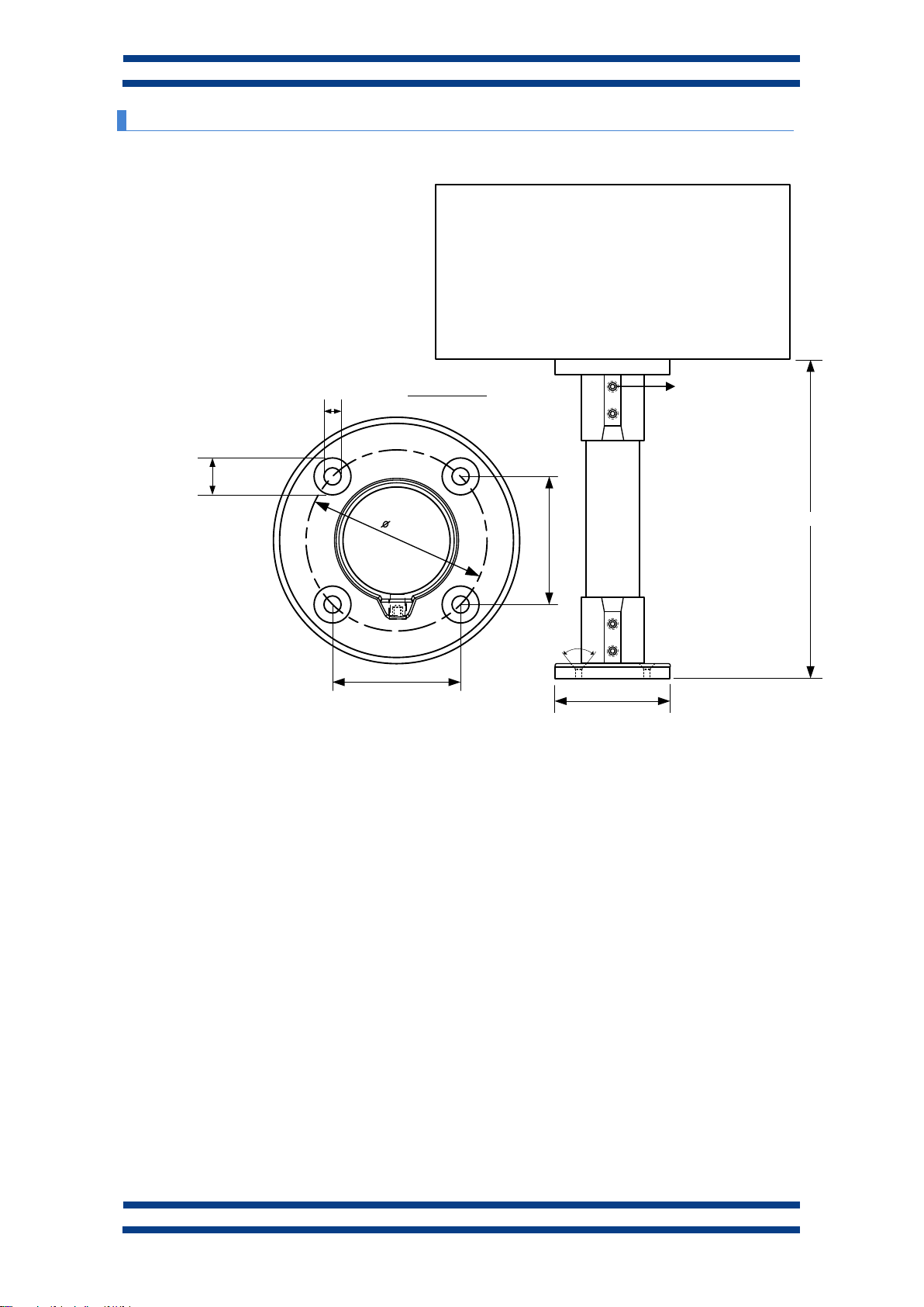
2.2. Dimensions and fixing of the displays ................................................................................2
2.2.1. Dimensions of the displays DN-107/3..........................................................................2
2.2.2. Dimensions of the displays DN-107/4..........................................................................2
2.2.3. Fixing of the displays....................................................................................................3
3. INSTALLATION......................................................................................................................... 1
3.1. Power supply ...................................................................................................................... 1
3.2. Wiring inputs.......................................................................................................................2
4. OPERATION.............................................................................................................................. 1
4.1. Initial reset........................................................................................................................... 1
4.2. Programming parameters...................................................................................................1
4.2.1. Enter to modify parameters..........................................................................................1
4.2.2. Exit modify parameters ................................................................................................1
4.2.3. Common parameters ................................................................................................... 2
4.2.4. Parameters of the function 03 (Counter)......................................................................2
4.2.5. Parameters of function 04 (Chronometer). ..................................................................4
4.2.6. Parameters of functions 05, 15 and 25 (Tachymeter). ................................................6
4.2.7. Parameters of function 06 (Binary) ..............................................................................7
4.2.8. Parameters of function 07 (Digit by digit)..................................................................... 7
4.3. Functions ............................................................................................................................ 8
4.3.1. Function 1. 8 bits multiplexed BCD.............................................................................. 8
4.3.2. Function 11. 8 bits multiplexed BCD............................................................................9
4.3.3. Function 2. Direct BCD. .............................................................................................10
4.3.4. Function 12. Direct BCD. ...........................................................................................10
4.3.5. Function 3. Counter....................................................................................................11
4.3.6. Function 4. Chronometer ...........................................................................................12
4.3.7. Function 5. Tachometer.............................................................................................13
4.3.8. Function 15. Tachometer with the less significant digit = 0. ...................................... 15
4.3.9. Function 25. Tachometer with the 2 less significant digit = 0. ...................................15
4.3.10. Function 6. Binary.................................................................................................... 15
4.3.11. Parameter 7. Digit by digit........................................................................................15
4.4. Colour configuration.......................................................................................................... 16

4.4.1. Using functions BCD, tachometer. binary or digit by digit.......................................... 16
4.4.2. Using functions counter or chronometer....................................................................17
4.4.3. Parameters to define the colour.................................................................................18
4.4.4. Work with only one colour..........................................................................................19

CHAPTER 1
INTRODUCTION
1-1
DN-107P displays series
1. INTRODUCTION
The family of numeric displays DN-107P has been designed to provide, in a single
display, the following functions:
Direct BCD. Only for 3 digits displays, with 12 inputs you may codify 3 digits.
Two more inputs lest you to codify the dot position.
Multiplexed BCD. For displays up to 4 digits. With 8 inputs you may codify all 4
digits values and their dots.
Counter. For displays up to 4 digits. Inputs for preset, reset, increase and
decrease. Input with fast and low speed selectable. Back-up for display value if no
power supply.
Tachometer. For displays of 3 or 4 digits. The display value is proportional to
the input frequency. Totally configurable.
Chronometer. For displays of 3 or 4 digits. It lets you configure a chronometer
with hours:minutes or minutes:seconds running in increment or decrement. The display
has inputs for preset, reset and input for run/stop.
Binary. For displays up to 4 digits. Displays the decimal value of binary codes
represented by the 14 inputs. Maximum value: 9999.
The size of digits of DN-107P is 57mm. The viewing distance from 30m to 120m, is one
of the most interesting characteristics.


CAPÍTULO 2 CARACTERÍSTICAS GENERALES 2-1
DN-107P displays series
2. GENERAL CHARACTERISTICS.
2.1. Electrical characteristics
2.1.1. Electrical characteristics of the DN-107/P displays.
Supply Voltage......................................88 to 264 VAC 47 to 63Hz.(Optional 24V)
Consumption ........................................35VA.
Display...................................................7 segments, 57mm high + decimal point.
................................................................Red led colour. Viewing distance: max 30 meters.
Parameter memory...............................Eeprom.
Control inputs .......................................12 to 24VCC. PNP NPN or Contact.
Relay option (R)....................................Contact SPDT. Maximum 48V 1A
Environmental Conditions...................Operation Temperature: -20 to 60ºC.
................................................................Storage Temperature: -30ºC to 70ºC.
................................................................Humidity: 5-95% RH non condensing.
................................................................Maximum environmental illumination: 1000 lux.
................................................................Sealing: IP41.

2-2 CARACTERÍSTICAS GENERALES CAPÍTULO 2
Display series DN-107P
2.2. Dimensions and fixing of the displays
2.2.1. Dimensions of the displays DN-107/3
245
120
70
40
All the measurements are in millimeters
2.2.2. Dimensions of the displays DN-107/4
245
120
70
40
All the measurements are in millimeters

CAPÍTULO 2 CARACTERÍSTICAS GENERALES 2-3
DN-107P displays series
2.2.3. Fixing of the displays
100
150/400/600
90 º
73,5
7
15
52
52
All the measurements are in millimeters
Fixing plate
M8


CAPÍTULO 3
INSTALACIÓN
3-1
DN-107P displays series
3. INSTALLATION
The installation of the DN-107NE is not particularly delicate but some important
considerations must be taken into account.
The display must not be anchored to places subject to vibrations, nor should it be
installed in places which generally surpass the limits specified in the display characteristics,
both in terms of temperature and humidity.
The degree of protection of displays DN-107P, is IP41, meaning that they are protected
against penetration by solid foreign objects of a diameter of about 1mm and against the vertical
fall of water droplets.
Displays DN-107P should not be installed in places with an illumination level in excess
of 1000 lux. Neither should the display be placed in direct sunlight as visibility would be lost.
In the electrical installation, proximity to lines of high intensity circulation and high
voltage lines must be avoided, as well as proximity to High Frequency generators and U/F
converters for motors.
3.1. Power supply
The power supply must be 88 to 264 VAC 47 to 63Hz or 19 to 36VDC.
The power supply conductor section will be in line with consumption and the ground
conductor will be a minimum section of 1.5mm².
The power supply connector for 220VAC has 5 contacts and is situated in the lower part
of the unit. Connect the power wires following the schema below
The power supply connector for 24VDC has 4 contacts and is situated in the lower part
of the unit. Connect the power wires following the schema below

3-2 INSTALLATION CHAPTER 3
Display series DN-107P
3.2. Wiring inputs
In all functions, the inputs should be between 12 to 26Vcc and allow PNP, NPN and contact
1 2 3 4 5 6 7 8 9 10 11 12 13
14 15 16 17 18 19 20 21 22 23 24 25
E1
E2
E3
E4
E7
E9
E8
E6
E5
E13
E12
E11
E10
E14
Vcc
0V
COM
SR1 SR2
PNP NPN
+
+
--
DB25 MALE CONECTOR
Auxiliary output voltage
DN-109 = 12V
DN-119 = 12V
DN-119C = 24V
DN-129 = 24V
DN-189 = 24V
Do not connect a
power supply
Each input has a different use depending on the function (BCD, counter, etc.). To know
how to wire them, see 4.3 “Functions”.
The inputs power supply must be between 12V and 26V CC with a maximum wave
of 500mV. Surpassing these values can damage the display. The auxiliary output can
supply up to 180mA

CHAPTER 4
OPERATION
4-1
DN-107P displays series
4. OPERATION
4.1. Initial reset.
Before connecting the display to the network, we must ensure that all of the connections
have been carried out correctly and that the display is firmly in place.
Each time we connect the display to the power supply network, an initial reset occurs
which tests all of the segments comprising the display. The test consists of the sequential
illumination of all of the digits with the number "8", all of the digits with the value "0", all of the
decimal points are lit up and finally the version code.
4.2. Programming parameters.
Displays DN-107 can be adapted to the specifications of each client by the
programming of parameters.
To program the parameters, the digits on the right of the display are used. The number
of the parameter is indicated by the digit on the left and the decimal point flashes while the digit
on the right is off.
4.2.1. Enter to modify parameters
In order to enter the sequence to modify the parameters, the Advance key “*” must be
pressed and held for three seconds. After this, the first parameters will be displayed, with the
digit flashing.
There are then two options:
1- Modify the parameter value
By pressing the Advance key "*", the values and the parameter number correlatively
can be selected.
To increase the parameter value, press the “+” key. After parameter 7 it returns to 1.
2- Select another parameter
In order to select another parameter, the parameter number must be made to flash
using the “*” key and then the new parameter may be selected using the “+” key. The number if
the parameter is: The left one when the decimal dot is activated in 2 digit displays. In 3 or more
digits displays the third digit starting from the right.
4.2.2. Exit modify parameters
In order to exit the sequence for modifying parameters, parameter F must be selected
then press “*”.

4-2 OPERATION CHAPTER 4
Display series DN-107P
4.2.3. Common parameters
4.2.3.1. Parameter 1: Function
This parameter determines the function of the display. Possible values are:
Parameter
value
Function
Digits
limit
01
8 bits. Multiplexed BCD. Models 3 or 4 digits. (-/White)
4
11
8 bits. Multiplexed BCD. Models 3 or 4 digits. (E/F)
4
02
Direct BDC. Only 3 digits models (-/White)
3
12
Direct BDC. Only 3 digits models. (E / F)
3
03
Counter
4
04
Chronometer
4
14
Chronometer format HH:MM:SS
4
05
Tachometer
4
06
Binary
4
07
Digit to digit
4
15
Tachometer with the less significant digit = 0
4
25
Tachometer with the 2 less significant digits = 0
4
See what each function does in 4.3 “Functions”.
In 01/11 (8 bit multiplexed BCD) and 02/12 (direct BCD ) functions, the function is
the only parameter configurable.
The chronometer function 14 is used in displays with format HH:MM . This function lets
to display the parameter number on the fourth digit.
4.2.4. Parameters of the function 03 (Counter)
Parameter 2. Co: Multiplying or splitter factor, maximum frequency and preset function.
Parameter 3. P1: Value of preset 1.
Parameter 4. P2: Value of preset 2.
Parameter 5. A1: Value of alarm 1.
Parameter 6. A2: Value of alarm 2.
Parameter 7. S1: Activation and temporization conditions of output 1.
Parameter 8. S2: Activation and temporization conditions of output 2.
Parameter 9. FA: Value of multiplying or splitter factor.
Parameter A. PU: Decimal point position.
Parameter F. in: Exit programming parameters.

CHAPTER 4
OPERATION
4-3
DN-107P displays series
4.2.4.1. Parameter 2 Co
This is a 2-digit parameter. The function of each digit is indicated in the following table.
Left digit
Operating modes
Right
digit
Automatic function
0
High counting frequency
0
Not activated
1
Low counting frequency
1
Counter = Alarm 1 →Reset
2
Counter = Alarm 2 →Reset
3
Counter = Alarm 1 →Preset 1
4
Counter = Alarm 2 →Preset 1
5
Counter = Alarm 1 →Preset 2
6
Counter = Alarm 2 →Preset 2
The digit on the left allows to adjust the type of sensor used. For contact type sensors
such as pushbuttons or relays, the low count frequency must be used to eliminate contact
bounces. For transistor output sensors such as inductive, photocells, etc. either of them can be
used considering that the low frequency admits a maximum frequency of 100Hz.
The automatic function (right digit) allows to modify the value of the counter when it has
a determinate value.
0 Counter’s value not modified.
1 Resets the counter if it is equal to alarm 1
2 Resets the counter if it is equal to alarm 2
3 Loads preset 1 if it is equal to alarm 1
4 Loads preset 1 if it is equal to alarm 2
5 Loads preset 2 if it is equal to alarm 1
6 Loads preset 2 if it is equal to alarm 2
The automatic function doesn’t work in high frequencies.
4.2.4.2. Parameter 3. P1: Preset 1 value
It can be from 0 to as many 9 as digits the display has.
4.2.4.3. Parameter 4. P2: Preset 2 value
It can be from 0 to as many 9 as digits the display has.
4.2.4.4. Parameter 5. A1: Alarm 1 value
It can be from 0 to as many 9 as digits the display has.
4.2.4.5. Parameter 6. A2: Alarm 2 value
It can be from 0 to as many 9 as digits the display has.
4.2.4.6. Parameter 7. S1: Activation and temporization conditions of output 1.
See 4.4.2 “Using functions counter or chronometer”
4.2.4.7. Parameter 8. S2: Activation and temporization conditions of output 2
See 4.4.2 “Using functions counter or chronometer”

4-4 OPERATION CHAPTER 4
Display series DN-107P
4.2.4.8. Parameter 9. FA: Value of the multiplying or splitter factor
Is the value at which the counter will be increased or decreased at each new impulse. It
can be programmed from the value 0.001 to 9999 (4 digit displays) and 0.01 to 999 (3 digit
displays.
The display behaves a multiplier for factors greater than 1 and a divisor for less than 1.
The position of the point is adjusted after modifying the last digit on the right (No digit
flashes), Press the + key to move the position of the point.
4.2.4.9. Parameter A. PU: Decimal point
Selects the decimal point position (the number of decimal digits). With a value of 0 no
decimal digits will be shown.
4.2.4.10. Parameter B. So: Exit modify parameters.
In order to exit the sequence for modifying parameters, select the last parameter in the
menu. Then press "*".
See the input wiring and examples in 4.3 “Functions”.
4.2.5. Parameters of function 04 (Chronometer).
The chronometer format and its maximum value depends on the display’s digit number:
3 Digits display: D.DD Maximum value: 9.59
4 Digits display: DD.DD Maximum value: 99.59
These displays can be configured to count hours/minutes or minutes/seconds.
Parameter 2. Co: Control of Hours-Minutes or Minutes-Seconds, increase/decrease
and function preset.
Parameter 3. P1: Value of preset 1.
Parameter 4. P2: Value of preset 2.
Parameter 5. A1: Value of alarm 1.
Parameter 6. A2: Value of alarm 2.
Parameter 7. S1: Activation and temporization conditions of output 1.
Parameter 8. S2: Activation and temporization conditions of output 2.
Parameter F. in: Exit programming parameters.

CHAPTER 4
OPERATION
4-5
DN-107P displays series
4.2.5.1. Parameter 2. Co
This is a 2 digit parameter. The function of each digit is indicated in the following table.
Left digit
Operating modes
Right
digit
Automatic function
0
Increase Hours/Minutes
0
Not activated
1
Decrease Hours/Minutes
1
Time = Alarm 1 →Reset
2
Inc/Dec Hours/Minutes →
Input 5
2
Time = Alarm 2 →Reset
3
Increase Minutes/Seconds
3
Time = Alarm 1 →Preset 1
4
Decrease Minutes/Seconds
4
Time = Alarm 2 →Preset 1
5
Inc/Dec Minutes/Seconds
→Input 5
5
Time = Alarm 1 →Preset 2
6
Time = Alarm 2 →Preset 2
7
Time = Alarm 1 →Stop
8
Time = Alarm 2 →Stop
In types of working 2 and 5 (Inc./Dec. Hours/Min. →input 5 and Inc./Dec. Min./Sec. →
input 5) the time is increased or decreased depending on the state of input5.
With the input 5 activated, the time increases. With the input 5 deactivated, the time
decreases.
The automatic function (right digit) permits modifying the stopwatch.
0 Chronometer value not modified.
1 Resets the chronometer if it is equal to alarm 1
2 Resets the chronometer if it is equal to alarm 2
3 Loads preset 1 if it is equal to alarm 1
4 Loads preset 1 if it is equal to alarm 2
5 Loads preset 2 if it is equal to alarm 1
6 Loads preset 2 if it is equal to alarm 2
7 Stops the chronometer if it is equal to alarm 1
8 Stops the chronometer if it is equal to alarm 2
4.2.5.2. Parameter 3. P1: Preset 1 value
The maximum value is 23h:59m or 59m:59s.
4.2.5.3. Parameter 4. P2: Preset 2 value
The maximum value is 23h:59m or 59m:59s.
4.2.5.4. Parameter 5. A1: Alarm 1 value
The maximum value is 23h:59m or 59m:59s.
4.2.5.5. Parameter 6. A2: Alarm 2 value
The maximum value is 23h:59m or 59m:59s.
4.2.5.6. Parameter 7. S1: Activation and temporization conditions of output 1.
See 4.4.2 “Using functions counter or chronometer”

4-6 OPERATION CHAPTER 4
Display series DN-107P
4.2.5.7. Parameter 8. S2: Activation and temporization conditions of output 2
See 4.4.2 “Using functions counter or chronometer”
4.2.5.8. Parameter B. So: Exit modify parameters.
In order to exit the sequence for modifying parameters, select the last parameter in the
menu. Then press "*".
See the input wiring and examples in 4.3.6 “Function 4. Chronometer”.
4.2.6. Parameters of functions 05, 15 and 25 (Tachymeter).
Parameter 2. FE: input frequency
Parameter 3. dt: display’s value.
Parameter 4. EL: updating time.
Parameter 5. Ll: Limit time without impulses.
Parameter 6. Pd: number of decimals.
Parameter 7. FA: mortifying factor.
Parameter F. in: Exits programming.
4.2.6.1. Parameter 2.FE: Input frequency.
Adjusts the value of the input frequency according to the following table:
Number of
digits
Maximum frequency
Minimum frequency
3
999
0,01
4
9999
0,001
The decimal point is selected with the increase key (+) after programming the frequency
4.2.6.2. Parameter 3.dI: Value of the display.
Selects the number shown when the frequency is equal to the input frequency of
parameter 2.
Number of
digits
Maximum value
Minimum value
3
999
0,01
4
9999
0,001
The decimal point is selected with the increase key (+ ) after programming the
frequency
4.2.6.3. Parameter 4.EL: Updating time
Selects the updating time of the display. The time is measured in tenths of seconds and
the rank is between 1 and 199 (0.1s and 19.9s).
With a big updating time there will be less changes on the frequency shown by the
display. If the input frequency is unstable, select a big updating time to reduce the display’s
changes.
4.2.6.4. Parameter 5.LI: Time without pulses limit.
Adjust the maximum time between two impulses. If this time is surpassed, the display
shows 0. The time is measured in seconds and the rank is between 1s and 99s

CHAPTER 4
OPERATION
4-7
DN-107P displays series
4.2.6.5. Parameter 6Pd: Number of decimals.
Selects the maximum number of decimal positions. If there isn’t enough space to show
all the integers numbers, the number of decimal positions will automatically decrease.
The possible values are: 0, 1, 2, 3, 4 and 9. A value of 9 indicates that there will be used
as many decimal positions as possible.
4.2.6.6. Parameter 7.FA: Average factor.
Selects the number of samples that are used to do an average and reduce the changes.
When the input frequency has a big change and you don’t want to see it, the average factor
reduces the change.
Each time that the data is updated, the new number erase the oldest. The possible
values are from 0 to 9. The number of samples are the average factor multiplied 5.
4.2.6.7. Parameter B. So: Exit modify parameters.
In order to exit the sequence for modifying parameters, select the last parameter in the
menu. Then press "*".
See the input wiring and examples in 4.3.7 “Function ”.
4.2.7. Parameters of function 06 (Binary)
4.2.7.1. Parameter A. PU: Decimal points
Selects the decimal point position (the number of decimal digits). With a value of 0 no
decimal digits will be shown.
4.2.8. Parameters of function 07 (Digit by digit)
Function 07 has no parameters, excepting in displays with colour or serial line options.

4-8 OPERATION CHAPTER 4
Display series DN-107P
4.3. Functions
4.3.1. Function 1. 8 bits multiplexed BCD.
The 8 bits multiplexed BCD function allows controlling displays from 3 to 4 digits with 8
data bits. The PLCs only need 8 data bits to control an 8 bits multiplexed BCD display.
The input’s power supply should be between 12V and 26V CC and can be connected to
PNP, NPN and CONTACT outputs. The function of each input is:
Inputs E5 and E6: If the four inputs are 0, with the E1to E4 the decimal point position is
codified. If not, they codify the digit’s position and E1, E2, E3 and E4 are the code of the value.
The digit 1 is in the right of the display.
Decimal point position
Digit
No point
1
2
3
4
E1
0
1
0
1
0
E2
0
0
1
1
0
E3
0
0
0
0
1
E4
0
0
0
0
0
Point selection
Digit point selection
1
2
3
4
ºE5
0
1
0
1
0
E6
0
0
1
1
0
Function
Symbol
:
+
/
%
-
º
= 01
Value
0
1
2
3
4
5
6
7
8
9
A
b
C
d
-
Space
= 11
Value
0
1
2
3
4
5
6
7
8
9
A
b
C
d
E
F
E1
0
1
0
1
0
1
0
1
0
1
0
1
0
1
0
1
E2
0
0
1
1
0
0
1
1
0
0
1
1
0
0
1
1
E3
0
0
0
0
1
1
1
1
0
0
0
0
1
1
1
1
E4
0
0
0
0
0
0
0
0
1
1
1
1
1
1
1
1
Table of contents
Other LARTET Monitor manuals