2GENERAL CHARACTERISTICS.
2.1 Electrical characteristics of the displays
2.1.1 Electrical characteristics of the DT-203 displays.
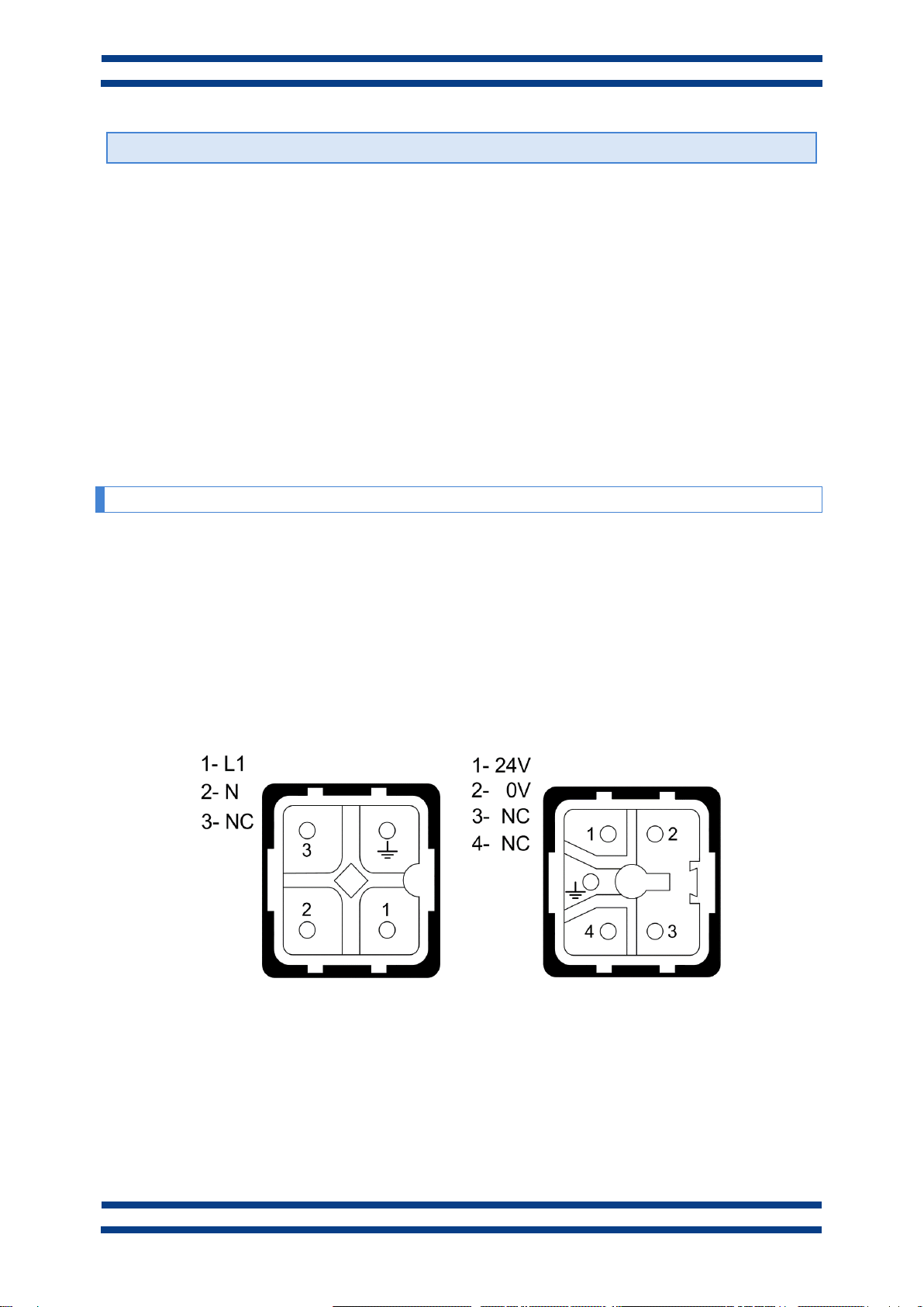
Supply Voltage...........................................88 to 264 VAC 47 to 63Hz. Option 24VDC.
Consumption .............................................See chapter 2.2.
Display .......................................................7x5 Dot matrix of 30mm high.
.....................................................................Red Led colour. Visibility 15 meters.
Parameter memory ....................................Eeprom.
Watch calendar ..........................................Second / Minute / Hour / Day / Month / Year.
Control inputs ............................................12 to 24Vcc. PNP, NPN or contact.
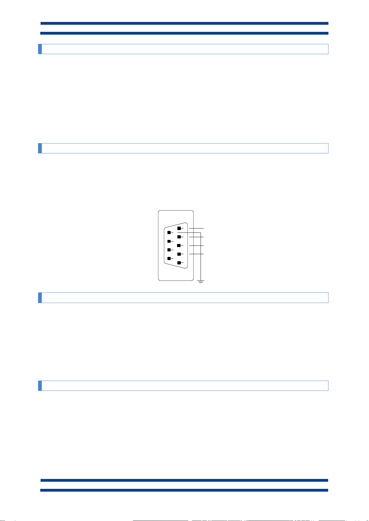
Serial line option (X)..................................RS-232 and RS-485. 9600 –19200 bauds
Relay option (R).........................................Contact SPDT. Maximum 48V 1A.
Environmental Conditions........................Operation Temperature: -20 to 60ºC.
.....................................................................Storage temperature: -30ºC to 70ºC.
.....................................................................Humidity: 5-95% without condensation.
.....................................................................Maximum environmental illumination: 1000 lux.
.....................................................................Sealing: IP41, IP54 and IP65.
2.1.2 Electrical characteristics of the DT-105 displays.
Supply Voltage...........................................88 to 264 VAC 47 to 63Hz. Option 24VDC.
Consumption .............................................See chapter 2.2.
Display .......................................................7x5 Dot matrix of 50mm high.
.....................................................................Red Led colour. Visibility 25 meters.
Parameter memory ....................................Eeprom.
Watch calendar ..........................................Second / Minute / Hour / Day / Month / Year.
Control inputs ............................................12 to 24Vcc. PNP, NPN or contact.
Serial line option (X)..................................RS-232 and RS-485. 9600 –19200 bauds
Relay option (R).........................................Contact SPDT. Maximum 48V 1A.
Environmental Conditions........................Operation Temperature: -20 to 60ºC.
.....................................................................Storage temperature: -30ºC to 70ºC.
.....................................................................Humidity: 5-95% without condensation.
.....................................................................Maximum environmental illumination: 1000 lux.
.....................................................................Sealing: IP41, IP54 and IP65.
2.1.3 Electrical characteristics of the DT-110 displays.
Supply Voltage...........................................88 to 264 VAC 47 to 63Hz. Option 24VDC.
Consumption .............................................See chapter 2.2.
Display .......................................................7x5 Dot matrix of 100mm high.
.....................................................................Red Led colour. Visibility 50 meters.
Parameter memory ....................................Eeprom.
Watch calendar ..........................................Second / Minute / Hour / Day / Month / Year.
Control inputs ............................................12 to 24Vcc. PNP, NPN or contact.
Serial line option (X)..................................RS-232 and RS-485. 9600 –19200 bauds
Relay option (R).........................................Contact SPDT. Maximum 48V 1A.
Environmental Conditions........................Operation Temperature: -20 to 60ºC.
.....................................................................Storage temperature: -30ºC to 70ºC.
.....................................................................Humidity 5-95% without condensation.
.....................................................................Maximum environmental illumination: 1000 lux.
.....................................................................Sealing: IP41, IP54 and IP65.