Lasermark LM800 User manual

LM800LM800
SeriesSeries
Electronic Self-Leveling Dual-BeamElectronic Self-Leveling Dual-Beam
Rotary LaserRotary Laser
LM800
Series
Electronic Self-Leveling Dual-Grade
Rotary Laser
LM800
LM800GR Instruction Manual
Manual de Instrucciones
Manuel d’Instructions
Manuale di Istruzioni
Bedienungsanleitung
Instruções de Utilização

2 • LM800 - LM800GR LM800 - LM800GR • 3
1
9
3
4
8
7
5
6
2
LM800
Series
Electronic Self-Leveling Dual-Beam
Rotary Laser
LM800
GR
MANUAL GRADE SETTING
1
3
4
5
2
LM800
Series
Electronic Self-Leveling Dual-Beam
Rotary Laser
LM800
GR
+
-
MANUALGRADESETTING
7
8
6
LM800 - Fig. 1 LM800GR - Fig. 2

Thank you for purchasing the LaserMark LM800 Series Electronic Self-Leveling
Rotary Laser Level.
Please read this manual thoroughly before operation
MODELS
LM800 LM800 Electronic Self-Leveling, Dual-Beam, Rotary Laser with Plumb
Down Laser. Dual-Grade when used with Remote Control.
LM800GR Electronic Self-Leveling, Single-Grade Rotary Laser. Dual-Grade when
used with Remote Control.
Copyright © 2005 CST/berger, All rights reserved.
The information contained herein is proprietary information of CST/berger and is subject to change
without notice.
This document shall not be copied or otherwise reproduced without CST’/berger’s written consent.
SAFETY AND CERTIFICATIONS
Working safely with this instrument is possible only when the operating and safety information are
read completely and the instructions contained therein are strictly followed.
The use of controls, adjustments, or the performance of procedures other than those specified
herein may result in hazardous radiation exposure.
Do not stare into the laser beams. Do not direct the laser beam at other persons. Do not
disassemble the instrument or attempt to perform any internal servicing. Laser class is indicated
on the instrument.
Repair and servicing of this laser are to be performed only by CST/berger or
authorized service centers.
This laser complies with all applicable portions of title 21 of the Code of Federal Regulations set by:
the Dept. Of Health, Education, and Welfare; the Food and Drug Administration; the Center for
Devices; and the Bureau of Radiological Health.
The instrument has also been tested and complies with the CE certification requirements set forth in the
EC regulations 89/336/EEC and EN 61000-6-1 (EN50082-1), EN 61000-6-3 (EN50081-1) and IEC 60-825-1.
4 • LM800 - LM800GR LM800 - LM800GR • 5
Fig. 3
Fig. 4
Fig. 5
X—AXIS ERROR
Y—AXIS ERROR
SPINDLE ERROR
Fig. 6
Fig. 7
Fig. 8
Y
+
–
+
–
X
Fig. 9
EN
LM800
Series
Electronic Self-Leveling Dual-Beam
Rotary Laser

LM800 - LM800GR • 7
1 Glass Enclosed
2 Self-Leveling (with ±5º) Rotary Laser
Beam
3 Anti-Drift System LED Indicator
4 Manual Mode LED Indicator
5 Battery Level LED Indicator
6 Remote Sensor eye
7 Top Cage with Gun Sight with “X” &
“Y” Identifiers
8 Heavy-Duty Handle – Built-in Trivet
(LM800 only) for Laydown and
Vertical Jobs with 5/8- 11 Tripod
Threads
9 Down Plumb Beam (LM800 only)
6 • LM800 - LM800GR
APPLICATIONS
Use your LM800 Series Self-Leveling Laser for many projects including:
Outdoor General Construction Applications & Site Preparation, Grading & Excavating,
Batterboards and Foundations, Masonry Work, Setting Concrete Forms, Machinery
Installation, Marking Elevation, Septic Work, Paving Roads, Driveways, Checking Depth of
Trenches.
Drop Ceiling Installation, Floors, Cabinets & Shelves, Carpentry, Pools, Decks & Patios,
Flagpoles, Aligning 90° Joints & Edges, Landscaping, Tile Work, Septic Work, Plumbing,
Batterboards, Fencing, Walls & Partitions, Remodeling, Siding Installation, Doors & Windows.
Operating Instructions for General Construction Applications
Note: A level plane of laser light is created by the rotating beam of the laser. The laser light can be
used to reference elevations with the use of a laser detector.
1. Place the instrument on a flat, level surface such as a tripod. Setup the instrument in an
area where it can not be obstructed and is set at a convenient height.
2. Press the “A” button. Allow the instrument to self-level.
3. Setup a "Benchmark".
Note: Setup a Benchmark
During the work day, periodically check your initial set-up to ensure that the laser reference has
not moved.
Establish, at a suitable distance (furthest possible), a benchmark (reference) on a stable surface
(ie. tree, building). Periodically during the work day, check the benchmark to ensure that your
setup has not moved.
Power Button (Allow 60
seconds for instrument to self-
level)
For LM800 – Use also to
activate the Plumb Down Beam
ADS Button– Anti-Drift System
ON | OFF
Manual Mode/Automatic Level
Button
Variable Rotation Button– 4
Speed Selections (LM800 Only)
Sweep Button– 4 Preset
Scanning/ Angles and spot.
(LM800 Only)
CW and CCW Button
Clockwise andCounter- Clock-
wise Head Positioning (Press
and Hold Button Moves the
Rotation More Quickly
For LM800– Use also during
Grade Mode.
Manual Grade Adjustment
Buttons
(LM800 GR Only)
ICONS
Reference in
the text
LM800
Series
Electronic Self-Leveling Dual-Beam
Rotary Laser
AA
LM800
Series
Electronic Self-Leveling Dual-Beam
Rotary Laser
BB
LM800
Series
Electronic Self-Leveling Dual-Beam
Rotary Laser
CC
LM800
Series
Electronic Self-Leveling Dual-Beam
Rotary Laser
DD
LM800
Series
Electronic Self-Leveling Dual-Beam
Rotary Laser
EE
LM800
Series
Electronic Self-Leveling Dual-Beam
Rotary Laser
FF
GG
HH
II
FEATURES - Fig. 1 & 2

LM800 - LM800GR • 98 • LM800 - LM800GR
Plumbing / Lay-Down (LM800 Only)
1. On a flat surface, place the instrument on its back using the built-in trivet (control
panel facing upward).
2. Press the “A” button once, and allow time for the instrument to self-level.
Variable Rotation Mode (LM800 Only)
The rotation mode will give you the option of increasing or decreasing the speed of
the rotating laser. This feature can be used to create a room-wide, 360° height
reference or vertical plumb line for general alignment, drop ceiling installation, and
more. Pressing the “D” button, will adjust the speed from 600, 300, 150, and 0 RPM.
Sweep or Scanning Mode (LM800 Only)
Instead of creating a room-wide reference line, the Sweep (Scanning) Mode
creates a shorter, brighter laser “chalk line” that can be used for leveling or
plumbing doors, windows, fixtures, and more. You may also use this feature to keep the instrument
from interfering with other lasers and detectors on site. Pressing the “E” button, will lengthen or
shorten the sweep of the laser beam. Preset angles of 0º, 10º, 45º, 90º, and 180º can be set.
Position the sweep area by using the “F” and “G” buttons.
Re-Leveling
If bumped or moved, the instrument will automatically attempt to re-level itself. On a job site, it
may be necessary to prevent re-leveling in order to prevent inaccurate measurements by the
operator. The Anti-Drift System (ADS) is used for this purpose (see Anti-Drift System - ADS). The
instrument can also be placed in Manual Mode to allow the instrument to continue operating when
out of level ( see Manual Mode ).
Axis Drive Error
If the laser is set up or tipped beyond its self-leveling range of ±5°, the laser head will initially
attempt to level; however, when the self-leveling limit is reached, an error will indicate an axis
error (Fig. 6). Turn the instrument OFF, move the instrument to a more level position, then turn the
instrument on again.
Spindle Motor Error
If the laser spindle motor fails to rotate or rotates outside of the
set speed, an error indicator will indicate a spindle motor error (Fig. 6). If this occurs, see
Troubleshooting.
4. Set the Variable Rotation Mode to the desired rotation speed of the laser head. Ideal speed
for use with laser detector is 600 RPM. (LM800GR: the rotation speed is fixed at 600 RPM)
5. Take elevation readings using the plane of laser light as a reference (Fig. 3). Follow the
Detector Operation Procedures in this manual.
Ceiling Grid Applications
1. Attach the laser to the optional wallmount bracket. Be sure the control buttons are facing
outward. Tightening the locking screw will secure the instrument to the bracket.
2. After installing the first piece of ceiling trim, attach the wallmount to it. Be sure the
wallmount is secure to the trim.
3. Press the “A” button. Allow the instrument to self-level.
4. Adjust the distance of the instrument from the grid, typically 1.5-inch (38mm) below the grid.
Loosen the adjustment screw and slide the instrument up/down on the wall mount. When
the desired height has been reached, tighten the adjustment screw to secure the instrument.
5. Setup a "Benchmark".
6. Install the ceiling grid. Attach the magnetic laser target to the ceiling trim being installed.
Adjust the height of the trim until the laser beam strikes the target (Fig. 4).
Laydown Applications (LM800 Only) - (Fig. 5)
1. Place the instrument in the laydown position on a flat, level surface.
2. Press the “A” button. Allow the
instrument to self-level.
3. Setup a "Benchmark"
OPERATIONS
Remove the laser from its carrying case.
Note:
Instruments are shipped with ADS on as the default setting. This setting can be changed by
the user (see Anti-Drift System - ADS )
Leveling
1. The instrument can stand alone on a level, sturdy surface or preferably secured to a 5⁄8" -11
surveyor’s tripod.
2. Press the “A” button once, and allow time (up to 60 seconds) for the instrument to self-level.
Note: The laser head may begin to rotate before leveling is complete. The self-leveling
speed is approximately 1° per 4 seconds.
3. After self-leveling, the instrument will begin operating in Rotation Mode for LM800-GR, last
select mode of operation (i.e. Sweep, Spot, Rotation Mode) for LM800.
LM800
Series
Electronic Self-Leveling Dual-Beam
Rotary Laser
LM800
Series
Electronic Self-Leveling Dual-Beam
Rotary Laser

LM800 - LM800GR • 1110 • LM800 - LM800GR
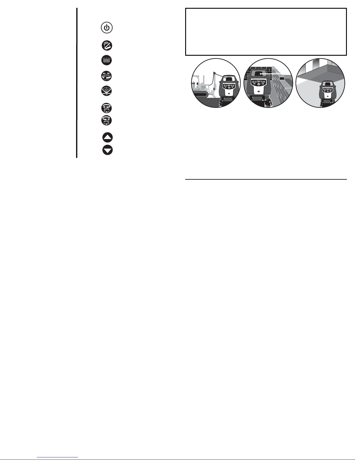
Grade Mode –Dual Axis Grade
The LM800 Series can also be used for Dual Axis Grade using the remote control (57-RC700).Fig. 8
The MODE button on the remote control when pressed will put the instrument in Manual Mode, if
ADS is not selected. Once in Manual Mode, the UP ("MORE") and DOWN ("LESS") arrow buttons on
the remote control adjusts the rotating head on the Y axis to the desired grade. The LEFT("MORE")
and RIGHT("LESS") arrow buttons on the remote control, adjusts the rotating head on the X axis to
the desired grade (Fig. 9).
Line Position Mode (LM800 Only) - Fig. 10
In this mode, the instrument allows you to fine-tune the location of your vertical (plumb) laser line.
For example, if you’ve established a plumb line and find that the line is slightly off to the left or right
of your target, use Line Position to jog the line into place without moving the entire instrument
(useful for floor and wall tile installation, walls or partitions, etc.). The laser will now remain aligned
to your target even if you enter other modes (Rotation, Spot, Sweep.)
Line Position mode is activated when the instrument is placed in the plumbing position (control
panel facing upward). While the instrument is in the pluming position, it can be used in Rotation,
Sweep, or Spot mode. To enter the Line Position mode and position the laser reference point, the
instrument must be rotating. Use the “F”and “G”buttons to position the laser reference point
while the instrument is rotating. If the instrument is in Spot mode or Sweep mode the “F” and “G”
buttons are used to move the spot or sweep.
NOTE: The LEFT and RIGHT Arrow buttons on the 57-RC700 Remote can be used to position the
laser reference point in any mode of operation. If the instrument is in Manual Mode, the Up and
Down Arrow buttons can also be used to position the laser reference point up and down.
Plumb Down Beam/Powering Off (LM800 Only)
The “A” button is a dual purpose button. This button is used to power the instrument on/off and to
turn on the plumb down beam. While the instrument is off, press the “A” button momentarily,
turning the instrument ON. Momentarily pressing the “A” button again, after the instrument is ON,
will toggle the plumb down beam on/off. To turn the instrument off, press and hold the “A” button .
The Manual and ADS LEDs will alternately flash to indicate that the “A” button can be released
(approx. 3 seconds).
Anti-Drift System – ADS
The Anti-Drift System, when ON, will signal to the operator that the instrument has
been moved out of level. When the instrument has been moved out of level, The
laser head will stop rotating and the beam and ADS LED will blink.
The default setting for ADS is user selectable. The default setting may be set to ADS ON or ADS
OFF. When the instrument is OFF, press and hold the “I” button (LM800-GR) or the “G” button
(LM800) and then press the “A” button. Once the instrument is on, turn the instrument off for 15
Sec and then back on. If ADS was ON (OFF), it will now be OFF (ON).
When the LM800 series is first turned on, the ADS feature does not begin recording for one minute. This
allows the instrument to be set up and adjusted.
To activate ADS, Turn off the Manual Mode (if it is on) and then press the “B” button. If after 1
minute, the instrument is disturbed and the ADS LED is flashing it is necessary to check any bench
marks that have been made and ensure the proper "HI" (Height of Instrument). Reset ADS, by
pressing the button one time, you will have an additional minute to set and check
your measurements.
To turn ADS off press the “B” button once. This will put the instrument into normal Auto Self-
Leveling mode.
Manual Mode
Manual mode disengages the leveling feature; allowing the instrument to be placed
in any position (to grade). To activate the Manual Mode, Turn off the ADS (if it is on)
and then press the “C” button. (Note: The instrument should be level before entering manual
mode to eliminate the possibility of error.) Once the button has been pressed the MANUAL light
will blink. Press the “C” button again to return to normal operation.
Note: When returning to normal operation the instrument must be within its leveling range. Re-set
the instrument to a level position before pressing the “C” button to the off position.
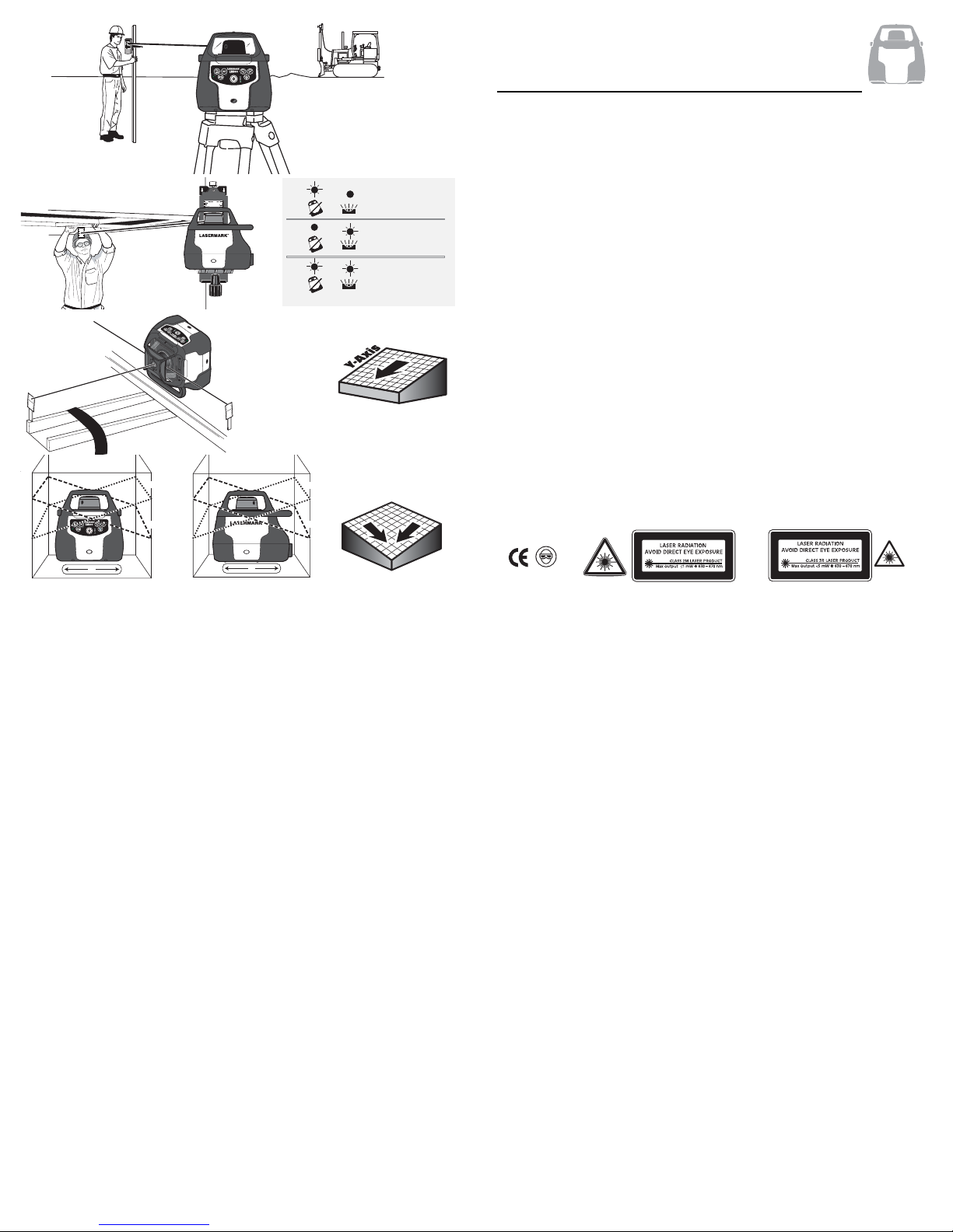
Grade Mode –Single Axis Grade
The single grade function is ideal for general site grading, checking excavations, landscaping and
drainage, and more.
The selected grade can be as much as a positive or negative 10%, and set in reference to the Y
axis of the instrument (Fig. 7), noted by the raised printing on the sides of the top cage of
the instrument.
The laser will react to “MORE” and “LESS” input. Allow the instrument ample time to react to the
input provided, between grade
setups or changes.
Note: LM800 will respond to “MORE” and “LESS” only in ROTATE mode, when using control panel.
NOTE: The total percent grade possible is from a perfectly level base position. If the
instrument is mounted on a tripod head which is not perfectly level, the grade
percentage range capability will be reduced by the slope of the base, as this affects
the tilt range of the laser head. For maximum grade range, ensure a level tripod head
using a spirit level before mounting your instrument.
LM800
Series
Electronic Self-Leveling Dual-Beam
Rotary Laser
LM800
Series
Electronic Self-Leveling Dual-Beam
Rotary Laser

LM800 - LM800GR • 1312 • LM800 - LM800GR
Upright Position Calibration – X axis
Keep the instrument in its current position. Power OFF the instrument.
1. Power On the instrument while holding the “C” button down, then release the “A” button. You
will know if Calibration Mode is activated when the MMAANNUUAALLand AADDSSLLEEDDs flash alternately.
2. The “C” and “B” buttons change the x-axis increments. The “C” button will produce a positive
(+) increment.
3. The “F” and “G” buttons change the y-axis increments. The “F” button will produce a positive
(+) increment. In the LM800GR the “H” and “I” Arrow buttons change the y-axis increments.
The “H” Arrow will produce a (+) increment.
4. You must raise or lower the beam to center between Position A and B on the target (Fig. 12).
The instrument will react to “+” and “–” input within the X+ quadrant. The instrument DOES
NOT react to adjustments until the instrument is forced to re-level (ie. rotate and
re-check Position “A”.
If Position B is below Position A, increase the increment (+).
If Position B is above Position A, decrease the increment (-).
5. Turn the instrument OFF. The adjustments are automatically saved.
You must now repeat the peg test to insure you have made the correct calibration. A peg test can
be done in Calibration Mode with a detector.
Upright Position Peg Test and Calibration – Y axis
To test the Y axis, mount the instrument on a tripod and place approximately 100 feet (30m) away
from the target, with the control side (Y– quadrant) facing the target; follow steps 2 thru 4 of
"Upright Position Peg Test – X axis". Calibrate as in "Upright Position Calibration – X axis", choosing
the Y axis to calibrate and adjusting “+” and “–” input as necessary within the Y+ quadrant (Fig.
13).
If you are unable to calibrate the instrument, or if the difference between points A and B is too
great to calibrate, please contact CST/berger or an authorized service center for assistance.
Laydown Position Peg Test – Z axis (LM800 Only)
1. To test the Z axis, place the instrument on its back using the built-in trivet (control panel facing
upward), 100 feet (30m) from a wall on a flat, level surface (Fig. 14).
2. Hang a plumb line down the wall at least 8 feet (2.5 m) long.
3. Press the “A” button and allow the instrument to self-level. If necessary, adjust the rotation
speed to easily view the laser beam on the wall. Orient the instrument parallel to the wall and
attempt to align with your plumb line.
If the laser line does not align with the plumb line, then calibration is necessary.
BATTERY REPLACEMENT
The battery indicator LED indicates the battery voltage level.
Green Fully Charged battery
Red Battery is Low, but will operate.
Flashing Red Battery is TOO Low for instrument to properly operate and battery should
be replaced/recharged immediately.
Rechargeable Battery Pack
The rechargeable battery pack (57-NB1000) will begin to perform optimally after five full charges
and discharges.
To charge the battery pack, ensure the power is off, and connect the charging plug to the battery
pack charge port. (1 - Fig. 11) Then plug the charger into the appropriate 110/230V AC outlet.
Charge time is typically around 8 hours depending on the discharge state of the battery pack. The
instrument can be charged and used at the same time, but the charge time will be extended.
CALIBRATION
Your LM800 Series Self-Leveling Laser is a sealed instrument and is calibrated to precise
accuracies at the factory. However, a calibration check is recommended before the initial use of
your laser, and then periodically from that point forward. Be sure to allow time (up to 60 seconds)
for the instrument to completely self-level before each check.
Upright Position Peg Test – X axis
1. To test the X axis, mount the laser on a tripod or a level, sturdy surface and place
approximately 100 feet (30m) away from a wall. Face the right side of the instrument to
the wall (Fig. 12).
2. Press the “A” button and allow the instrument to self-level. Using the laser detector, locate
and mark the position of the laser line on the
wall Position “A”).
3. Loosen the instrument from the tripod and rotate the instrument 180°. Ensure that the height of
the tripod does not change, as this will affect your results. Secure and re-level the instrument.
4. Again, using the laser detector, locate and mark the position of the laser on the wall (Position “B”).
5. Mark the centerline between Position A and Position B (Position “C”). Callibration is necessary
if the vertical difference between Position A and Position C or Position B and Position C is
greater than the specified accuracy.
LM800
Series
Electronic Self-Leveling Dual-Beam
Rotary Laser

LM800 - LM800GR • 1514 • LM800 - LM800GR
Vertical Leveling No Yes
Grade Capability with Control Panel– Single Axis (Up to ±10%)
with Remote– Dual Axis (Up to ±10%)
Self-Leveling Range ±5° ±5°
Battery Power 15± Hours Continuous Use with Fully Charged
Ni-Cad Battery Pack (variable w/ temp./usage)
Rotation Speed Fixed Variable (0,150, 300, 600)
Weight 5.5 ±lbs (2.5kg) with Battery
Visible Split Beam No Yes
Plumb Down Beam No Yes, using the POWER button
Scanning Feature No Yes
Operating temperature 22°F to 120°F (-6°C to 49°C)
Environment IP67 – Waterproof
TROUBLESHOOTING
The following information lists basic tests that can be performed to check the LM800 Series in the
event of poor performance.
Rechargeable Battery Pack: For maximum battery life, the battery pack must contain a full charge.
The batteries will begin to perform optimally after five full charges and discharges.
Instrument does not rotate or self-level, or produces “Error” message: Ensure that the instrument
is within its self-leveling range. Reset the internal processor by turning power OFF, wait 15
seconds, and power the instrument ON again. If the instrument rotates but does not self-level, be
sure that MANUAL mode is not selected.
If troubleshooting is not effective, please contact CST/berger or an authorized service
center for assistance.
WARRANTY
Two Year Warranty. CST/berger, a division of Stanley Works, warrants the LM800 against defects
in material and workmanship for a period of two years from the date of purchase. Deficient
products will be repaired or replaced at CST/berger's discretion.
For warranty and repair information, contact your local distributor.
For U.S.: Before returning the instrument to CST/berger, call (815) 432-9200 for a
Return Authorization Number from our Customer Service Department.
Laydown Position Calibration – Z axis (LM800 Only)
Keep the instrument in its current position. Power OFF the instrument.
1. Power ON (”A” button) the instrument while holding the “C” button down, then release the
“A” button. You will know if Calibration Mode is activated when the MMAANNUUAALLand AADDSSLLEEDDs
flash alternately.
2. The “C” and “B” button change the axis increments. The “C” button will produce a positive
(+) increment.
3. Select the “C” button to position the rotating beam counterclockwise, or the “B” button to
position the rotating beam clockwise into alignment with your hanging plumb line. For
example, the rotating beam must be positioned counterclockwise to align with the plumb line,
so you must select the “C” button (See Figure 14).
4. Turn the instrument OFF. The adjustments are automatically saved.
You must now repeat the peg test to insure you have made the correct calibration. A peg test can
be done in Calibration Mode.
MAINTENANCE AND CARE
Always clean the instrument after use. Use a soft, dry cloth to remove any dirt or moisture from the
instrument. Do not use benzene, paint thinner, or other solvents to clean the instrument. Store the
instrument in its case when not in use. Batteries should be removed before long-term storage.
ENVIRONMENTAL PROTECTION
Recycle raw materials instead of disposing as waste. The machine, accessories and
packaging should be sorted for environmental-friendly recycling. Do not throw used
batteries into waste, fire or water but dispose of in an environmentally friendly manner according to the
applicable legal regulations.
SPECIFICATIONS
Description LM800GR LM800
Operating Range Up to 2000’ (610m) diameter with laser detector
Class & Diode Power 2M - 650 nm 2M - 635 nm High Power
Leveling Accuracy ±1/16-in @100’ 1/16”@100’
(+/-1.5 mm @ 30m) (+/-1,5 mm@30m)
Vertical Accuracy N/A 1/8”@100’(6,4 mm@30m)
Leveling Type Electronic Self-Leveling
Horizontal Leveling Yes Yes

LM800 - LM800GR • 1716 • LM800 - LM800GR
Features (Fig. 16)
1 LCD readout window 5. Beam Resolution
2 Speaker 6. Volume ON | OFF
3 Beam Capture Window 7. LCD Readout Window (LD-400 and LD-120 only)
4 Power ON/OFF 8. Battery Door
Power
A 9-volt battery will provide up to 3 months of typical usage. When the instrument is turned on and
the low battery symbol remains lit, the battery should be replaced.
Operation– Laser Detector
1. Mount the instrument onto a sighting rod if you are using one. Turn on the instrument by
pressing the ON/OFF pad. The LCD symbols will momentarily flash and the “coarse” beam
indicator symbol will remain lit and the audio signal will be on (Fig. 17).
2. Expose the beam capture window of the laser detector towards the direction of the
rotating laser.
3. Slowly move the laser detector in an upward and downward direction until the LCD beam
indicator arrows appear and/or a pulsing audio signal is heard. Use the Beam Resolution
feature to choose between the coarse/low setting, used for approximating level or for initial
locating of the center level point, the medium setting, used for greater accuracy, and the
fine/high setting, used for the most accurate pinpointing of level. (to see the available
Resolutions, please refer to the Specs Table).
4. Move the detector upward when the low beam indicator light is lit (with volume on, a short
pulsing audio tone is heard). Move the detector downward when the high beam indicator
arrow is lit (with volume on, a long pulsing audio tone is heard). When the beam is level, the
level beam indicator line will be lit and a solid audio tone will be heard.
If the detector is not struck by a laser beam after 5-8 minutes, the detector will automatically shut
itself off to preserve battery life. Turn the instrument back on using the power button.
Special Features– Laser Detector
The LCD display of the detector LD-400 has seven distinct channels of information, indicating the
position of the detector in the plane of laser light, as indicated in Fig. 18 (the detectors LD-120 and
LD-100N have three).
As you move the detector closer to the center, the arrows fill in to indicate the laser position.
The detector has a unique memory feature, which preserves the last position of the laser beam if
the detector is moved out of the plane of laser light, as well as built in electronic filtering for bright
sunlight and electromagnetic interference.
The detector LD-400 has three speaker selections (Off, Loud (105dBA) and Louder (125+ dBA)),
whereas the models LD-120 and LD-100N have only two (Off and On).
CST/berger's liability under this warranty is limited to repair or replacement of the instrument. Any
attempt to repair the product by other thanfactory authorized personnel will void this warranty.
Calibration, batteries and maintenance are the responsibility of the user. Where permitted by law,
CST/berger is not responsible for incidental or consequential damages.
Agents of CST/berger cannot change this warranty. CST/berger is not responsible for damage
resulting from wear, abuse, or alteration of this product. The user is expected to follow
ALL operating instructions.
This warranty may provide you with additional rights that vary by state, province or nation.
LASERMARK is a registered trademark of CST/berger.
IMPORTANT NOTE: The customer is responsible for the correct use and care of the instrument.
Moreover he is completely responsible for checking the job along its prosecution, and therefore for
the calibration of the instrument. Calibration and care are not covered by warranty.
Subject to change without notice
57-RC700 REMOTE CONTROL - (Fig. 15)
The remote control can be used up to a maximum of 100 feet (30 m) away from the instrument. The
remote must be pointed towards the instrument for proper operation. Requires 2 ‘AA’ Alkaline
batteries.
(1) Variable Rotation adjusts to preset rotation speeds–LM800 Only
(2) Line Positioning (only in lay-down position) – LM800 Only
X-Axis Grade Adjustment– LM800/LM800GR
(3) CCW- positions the laser in sweep or spot mode -- LM800 Only
(4) N/A–
(5) Y-Axis Grade Adjustment LM800/LM800GR
(6) Scan/Sweep Mode- adjusts to preset sweep angles– LM800 Only
(7) CW-positions the laser in sweep or spot mode -- LM800 Only
(8) Manual Mode– Places instrument in manual grade if ADS is not selected.
UNIVERSAL LASER DETECTOR
Introduction
The LaserMark® Universal Laser Detector aids in locating and targeting a visible or invisible beam
emitted by a rotary laser; perfect for use in outdoor conditions, where sunlight and distance may
make locating the beam more difficult. The laser detector includes a rod clamp which allows to
mount the detector onto square, round or oval sighting rods.

LM800 - LM800GR • 1918 • LM800 - LM800GR
Gracias por su confianza en nuestros niveles láser LaserMark LM800.
Se recomienda leer atentamente estas instrucciones de uso, antes de la primera
utilización del láser.
MODELOS
57-LM800 LaserMark Láser autonivelante electrónico Horizontal / Vertical, Doble
Plomada arriba y abajo. Doble Inclinación manual en posiciones horizon
tal y vertical, utilizando el mando a distancia
57-LM800GR LaserMark Láser autonivelante electrónico Horizontal con Inclinación
manual. Doble Inclinación manual, uilizando el mando a distancia
Copyright© 2005 CS/berger. Derechos reservados.
Toda esta información es propiedad de CST/berger. Este documento no debe ser copiado
o reproducido sin el consentimiento escrito de CST/berger.
SEGURIDAD Y ESPECIFICACIONES
Es posible trabajar con el aparato sin peligro, sólo después de haber leído atentamente las
instrucciones para el uso y las advertencias de seguridad, y siguiendo estrictamente las
instrucciones.
El uso de instrumentos ópticos, controles, ajustes o procedimientos de funcionamiento distintos a
los especificados en el presente manual pueden provocar una exposición a radiación peligrosa. La
clase del láser está indicada en la etiqueta.
No mirar hacia el rayo. No apuntar el rayo láser hacia otras personas. No desmontar el
instrumento, ni intentar hacer ninguna reparación. La reparación y el mantenimiento de este láser
deben ser realizados solamente por CST/berger o centros de servicio autorizados.
El equipo cumple con todas las especificaciones del artículo 21 del Código de Regulación Federal
(U.S.A.) el Departamento de Sanidad, Educación, Alimentación y del Centro para la
Salud Radiológica.
El láser también cumple con las especificaciones CE según las normas 89/336/EEC, EN 61000-6-1
(EN50082-1), EN 61000-6-3 (EN50081-1) y IEC 60-825-1.
Care of Your Universal Laser Detector
This instrument is gasket sealed for water and dust protection. Use a soft, dry cloth to remove any
dirt or moisture from the instrument before storage. Do not use benzene, paint thinner, or other
solvents to clean the instrument. Remove battery before long-term storage of the instrument.
Specifications
* Note: Sensitivity values based on standard conditions with most lasers; may vary slightly due to
make, manufacturer, beam size, or working conditions.
Subject to change without notice
DDeessccrriippttiioonnLLDD--440000LLDD--112200LLDD--110000NN
Dimensions 6.6” H x 3“ W x 1” D (169mm x 76mm x 25mm)
Weight 10 oz. (275g)
Range Up to 2000-ft (610m) Diameter
Beam Resolution *
Fine ±0.75mm
Medium ±1.5mm
Wide ±3mm
Medium ±1.5 mm
Wide ±3 mm
Medium ±1.5mm
Wide ±3mm
Readout LCD, 2 windows LCD, 2 windows LCD, 1 window
Power One 9-volt battery provides 3 months of typical usage
Warranty 1 year (For warranty conditions see “Warranty”)
LM800
Series
Electronic Self-Leveling Dual-Beam
Rotary Laser
E

LM800 - LM800GR • 2120 • LM800 - LM800GR
APLICACIONES
Utilice su nivel láser de Nivelación Automática para estos y muchos otros proyectos:
NIVELACIONES EN INTERIORES: Instalación de falsos techos, armarios, mostradores, ventanas.
NIVELACIONES EN EXTERIORES: Porches, cubiertas, cercados, postes, jardines,
inclinaciones, cementos.
Instrucciones de manejo en aplicaciones generales
Nota: El rayo láser giratorio crea un plano de luz a nivel. Esta luz láser puede utilizarse junto con
un receptor láser como referencia de elevaciones.
1. Coloque la unidad en una superficie llana y nivelada (por ejemplo, un trípode). Instale la
unidad en una zona libre de obstáculos al paso del láser y situada a una altura adecuada.
2. Pulse el botón de encendido. Deje que la unidad se nivele automáticamente.
3. Fije una marca de referencia.
4. Fije el modo de rotación variable a la velocidad a la que quiera que gire el cabezal del láser.
La velocidad ideal para el uso con receptor láser es de 600 r.p.m. (El láser LM800GR tiene
una velocidad de rotación fija de 600 r.p.m.)
5. Tome las medidas de elevación tomando como referencia el plano de luz láser (Fig. 3). Siga
las instrucciones para el manejo del receptor que aparecen en este manual.
1 Cabeza protegida mediante
urna de cristal
2 Cabeza rotatoria, campo de
autonivelación” de +/- 5°
3 Indicación alarma
antimovimiento (ADS)
4 Indicación Funcion Manual
5 Indicación LED de carga de
las pilas
6 Tres receptores del mando
a distancia
7 Punto de mira con
indicaciones de los ejes “X”
y “Y”
8 Asa de transporte / Rosca
5/8” x 11 para colocar
verticalmente el láser en
trípode
9 Salida de la plomada hacia
abajo (sólo LM800)/ Rosca
5/8” x 11 estandard
IInntteerrrruuppttoorrOONN//OOFFFF(conexión /
desconexión) – 60 segundos para
que el láser se autonivele.
(Sólo para LM800 – Una segunda
pulsación apaga la plomada de
abajo / para apagado total
mantener pulsado el interruptor
unos dos segundos)
IInntteerrrruuppttoorrsistema de alarma
antimovimiento ((AADDSS))
IInntteerrrruuppttoorrffuunncciióónnmmaannuuaall
IInntteerrrruuppttoorrddeeaajjuusstteeddeellaa
vveelloocciiddaaddde la cabeza. Cuatro
velocidades (LM800GR – sólo una
velocidad)
IInntteerrrruuppttoorr
ddee““bbaarrrriiddoo””. 4 ángulos
fijos y punto fijo (Sólo LM800)
IInntteerrrruuppttoorreessddiirreecccciioonnaalleessddeellaa
ccaabbeezzaa. Rotación en ambos
sentidos. Manteniendo presionado
los botones se aumenta la
velocidad de rotación de la cabeza
(LM800 – Utilizar también en el
Modo Inclinación Manual)
IInntteerrrruuppttoorreessppaarraaaajjuussttaarrllaass
iinncclliinnaacciioonneessmanuales (sólo
LM800GR)
DESCRIPCIÓN DEL PANEL
DE CONTROL
Referencia
nel texto
CARACTERISTICAS
Fig. 1 & 2
LM800
Series
Electronic Self-Leveling Dual-Beam
Rotary Laser
LM800
Series
Electronic Self-Leveling Dual-Beam
Rotary Laser
LM800
Series
Electronic Self-Leveling Dual-Beam
Rotary Laser
LM800
Series
Electronic Self-Leveling Dual-Beam
Rotary Laser
LM800
Series
Electronic Self-Leveling Dual-Beam
Rotary Laser
LM800
Series
Electronic Self-Leveling Dual-Beam
Rotary Laser
AA
BB
CC
DD
FF
EE
HH
GG
II
ESTABLECER UNA REFERENCIA
Durante el día de trabajo, compruebe periódicamente la configuración inicial para asegurarse de
que la referencia del láser no se ha movido.
Establezca una marca de referencia en una superficie fija, como un árbol
o un edificio, a una distancia adecuada (lo más lejos posible). Compruebe periódicamente la
marca de referencia a lo largo del día para asegurarse de que la configuración no ha variado.

Rotación vertical (LM800)
1. Coloque la unidad en posición “tumbada” sobre una superficie nivelada lisa utilizando la
asa, con el panel de control hacia arriba.
2. Presionar el interruptor “A” una vez, y dejar aprox. 60 segundos al láser para que se
ponga a nivel.
Para un ajuste fino de la línea vertical o de la plomada, ver “Función Posición Línea”.
Rotación de la cabeza (LM800)
Con este “Funcion Rotación” se puede aumentar o disminuir la velocidad de
rotación de la cabeza.
Presionando varias veces el interruptor “D”, se consigue una velocidad de 600, 300,
150 o 0 RPS.
Funcion “barrido” (LM800)
El funcion “barrido” del láser LM800 crea una línea láser muy visible, que puede ser
dirigida girando la cabeza rotatoria. Esto es particularmente útil cuando hay que
delimitar el área del rayo láser para evitar interferencias con otros láser o
receptores en la obra. Además con esta función se aumenta de una manera considerable la
visibilidad del rayo láser. Se puede utilizar esta función en horizontal y en vertical.
Presionando el interruptor “E” se elige entre ángulos fijos de 0°, 10°, 45°, 90° y 180º. Con los
interruptores “F” y “G” se dirige la cabeza rotatoria
Auto-nivelación
En caso de que el instrumento sea golpeado o desnivelado, el instrumento intenta auto-nivelarse
automáticamente. En la obra, más vale evitar que el láser vuelva a auto-nivelarse, para evitar
medidas imprecisas; para eso se utiliza la Función alarma antimovimiento (ADS).
Es también posible seleccionar la Función Manual para permitir que el láser siga trabajando
cuando esté fuera de nivel (ver “Función Manual”).
Error “fuera de nivelación”
En caso que el láser sea golpeado más allá de su “campo de autonivelación” de +/- 5°, el láser
intenta autonivelarse, pero cuando ha llegado a su límite, una indicación evidenciará un error (Fig.
6). Apagar el láser, ponerlo en una posición más nivelada, luego encenderlo de nuevo.
Error “Spindle Motor”
Si con el motor en funcionamiento la cabeza no gira, se produce un error de Spindle indicado
mediante el encendido intermitiente de los dos LED rojos (Fig. 6). Dirigirse a la sección “Solución
de Problemas”.
LM800 - LM800GR • 2322 • LM800 - LM800GR
Uso en falsos techos con rejilla
1. Monte el láser en el soporte de pared (opcional). Asegúrese de que los botones de control
queden mirando hacia afuera. La unidad se afianza al soporte apretando el tornillo
de sujeción.
2. Después de instalar el primer puntal en el techo, fíjele el soporte de pared. Asegúrese de
que el soporte de pared está firmemente sujeto al puntal.
3. Pulse el botón de encendido “A”. Deje que la unidad se nivele automáticamente.
4. Ajuste la distancia del aparato a la rejilla (normalmente unos 38 mm por debajo de ésta).
Afloje el tornillo de ajuste y deslice la unidad hacia arriba o abajo a lo largo del soporte de
pared. Cuando logre la altura deseada, apriete el tornillo de ajuste para afianzar la unidad.
5. Fije una marca de referencia.
6. Instale el enrejado en el techo. Instale el objetivo magnético del láser al puntal del techo
que va a montar. Ajuste la altura del puntal hasta que el rayo láser alcance el objetivo
magnético (Fig. 4).
Aplicaciones en superficie (sólo LM800) – (Fig. 5)
1. Coloque la unidad en una superficie plana y equilibrada.
2. Pulse el botón de encendido. Deje que la unidad se nivele automáticamente.
3. Fije una marca de referencia.
FUNCIONAMIENTO
Sacar el láser del maletín.
Nota: TODOS LOS INSTRUMENTOS VIENEN DE FÁBRICA CON LA FUNCIÓN ADS POR DEFECTO.
No obstante el usuario puede variarlo (ver “Sistema Alarma Antimovimiento – ADS”).
Nivelación
1. El láser se puede colocar sobre cualquier superficie lisa o montarlo en un trípode estándar
con rosca de 5/8” x 11.
2. Presionar el interruptor “A” una vez, y dejar aprox. 60 segundos al láser para que se
autonivele.
Nota: La cabeza puede empezar a girar antes que el láser se ha nivelado. La velocidad de
nivelación es de aprox. 1° cada 4 segundos.
3. Cuando el láser esté nivelado, empieza a funcionar en “modo rotación” en el modelo LM800-
GR; en el último modo seleccionado antes de apagarlo (por ej. Barrido, Punto Fijo, Rotación)
en el modelo LM800.
LM800
Series
Electronic Self-Leveling Dual-Beam
Rotary Laser
LM800
Series
Electronic Self-Leveling Dual-Beam
Rotary Laser

Nota: El LM800 reaccionará al cambio de grados sólo en Función Rotación, cuando se utilize los
botones del panel de la unidad. Con el mando a distancia se pueden cambiar los grados
indipendientemente de la función (PUNTO, BARRIDO, ROTACION).
Utilizando el mando a distanzia 57-RC700, se puede realizar la doble inclinación (Fig. 8), mediante la
desconexión del ADS, pulsación de la tecla “Función Manual”, y la utilización de los cuatro
botones indicados con el símbolo “punta flecha”.
Las dos flechas arriba y abajo inclinan el plano Y y las flechas derecha e izquierda inclinan el
plano X (Fig. 9).
Función posición línea (LM800) – Fig. 10
En esta función, la unidad permite ajustar la posición del plano vertical (plomada).
Por ejemplo, si ha establecido una orientación y se da cuenta que está desviada hacia la derecha
o izquierda del objetivo, use la función “Posición de la Línea” para colocar la línea en su lugar sin
tener que mover la unidad (útil para la instalación de paredes y tabiqueria, ecc.). El láser se
mantendrá alineado, incluso al cambiar a otras funciones (rotación, punto, punto-a-punto).
Posición de línea será activado únicamente si la unidad es situada en posición de nivelación
vertical (panel de control hacia arriba). En esta posición el láser puede trabajar en funcion
Rotación, Barrido, o Punto. Para activar la Función Posición Línea y orientar la línea, el láser tiene
que estar en Rotación. Use los botones “F” y “G”, para ajustar la posición del punto de referencia
laser. Cuando el láser esté en función Punto o Barrido, presionando estos botones “F” y “G”, se
mueve el punto láser en el sentido contrario a las agujas del reloj o en el sentido de las agujas del
reloj, así como si el láser estuviera en nivelación horizontal.
Nota: Con el mando a distancia 57-RC700 utilizar el botón izquierdo o el botón derecho para
orientar la posición del plano láser, independientemente que el láser esté en Función Rotación,
Punto o Barrido.
Se puede analogamente orientar el plano vertical utilizando como referencia el punto laser
horizontal (emitido desde la parte superior de la unidad); el plano vertical se moverá manteniendo
un ángulo de 90º con el punto.
NOTA: En Función Manual, se pueden también utilizar los otros dos botones “punta flecha” para
inclinar el plano vertical.
LM800 - LM800GR • 25
Sistema de alarma antimovimiento - ADS –
Esta función avisa al usuario cuando el láser puede variar la cota de trabajo. Con
esta función conectada, cuando la cota del instrumento varíe porqué por ej. el
trípode se ha movido, la cabeza detiene su rotación, y la indicación ADS y la señala
láser parpadean. Esta función puede ser activada tanto en la rotación horizontal como en la
rotación vertical (LM800).
El usuario puede ajustar por defecto en ON o OFF. Con la unidad apagada, mantener pulsado el
botón “I” (LM800GR) o “G” (LM800), y después apretar el botón “A”. Cuando la unidad está
encendida, apagarla durante 15 segundos y encenderla otra vez.
Si la función ADS estaba ajustada por defecto en ON (OFF), estará ahora en OFF (ON).
Cuando se activa la función ADS, hay que esperar 1 minuto para que esta función sea realmente
activa. Eso permite el ajuste del láser.
Para activar la función ADS, desconectar la Función Manual, si está conectado, presionando “C”,
y depués presionar “B”.
Después de un minuto, si el láser está golpeado y la indicación ADS parpadea, el usuario tiene que
dirigirse al láser, controlar que ha pasado y luego nivelarlo, presionando el interruptor ADS (“B”);
ahora tiene otro minuto para ajustar el láser. Presionando el interruptor “B” otra vez se
desconecta la función ADS y el láser vuelve a auto-nivelarse normalmente.
Función manual
La función manual desconecta la autonivelación del láser; así se puede colocar el
instrumento en todas las posiciones.
Para activar la función manual, apague el ADS (si está conectado), luego presione el interruptor
“C”. (Nota: Se aconseja esperar que el láser esté nivelado y la cabeza gire, antes de activar el
funcion manual, así se elimina la posibilidad de error). Después el indicador de “Función Manual”
parpadeará. Presione otra vez el interruptor “C” para volver a trabajar en funcion autonivelante.
Nota: Cuando se vuelva a trabajar en función autonivelante, el láser tiene que estar posicionado
dentro de su campo de autonivelación; antes de presionar este interruptor, asegúrese que el láser
esté bastante nivelado.
Ajuste de las Inclinaciones - Inclinación manual individual
Esta función es ideal para hacer en general inclinaciones en una obra, controlar excavaciones,
drenaje etc.
La inclinación seleccionada puede ser tanto positiva como negativa en un 10% máximo, y ajustar
una referencia al eje Y de la unidad (Fig. 7).
Dar tiempo a la unidad para reaccionar entre cambios de grados.
24 • LM800 - LM800GR
LM800
Series
Electronic Self-Leveling Dual-Beam
Rotary Laser
Nota: Se puede obtener el 10% sólo cuando el láser está sobre una base perfectamente
nivelada. Si por ejemplo el trípode no está perfectamente nivelado, el porcentaje de inclinación
posible será disminuido de la inclinación de la cabeza del trípode, pues esta influye en el campo
de movimiento de la cabeza del láser.
LM800
Series
Electronic Self-Leveling Dual-Beam
Rotary Laser

Calibración del error horizontal– Eje X
No mueva el instrumento de su posición actual. Apague la unidad.
1. Encienda el láser mientras tiene presionado el interruptor “C”; luego soltar el botón “A”. El
láser está ahora en el función “calibración” y para indicarlo los LEDs de “Función Manual
”y de “ADS” parpadean alternadamente.
2. Los botones “C” y “B” cambian los incrementos del eje X. El botón “C” sube el rayo.
3. Los botones “F” y “G” cambian los incrementos del eje Y. El botón “F” sube el rayo.
LM800GR: los botones “H” y “I” cambian los incrementos del eje Y. El botón “H” sube el
rayo.
4. Hay que subir o bajar el rayo láser para buscar el centro entre los puntos “A” y “B” en la
pared (Fig. 12). La unidad reaccionará al cambio de los incrementos en el cuadrante X(+). La
unidad no reacciona a los ajustes hasta que está forzada a volver a nivelar (rotar y volver a
comprobar el punto “A”).
Si la marca B está bajo A, hay que subir el rayo presionando el botón “C”
Si B está arriba de A, hay que bajar el rayo presionando el botón “B”.
5. Apague el láser. Las correcciones se guardan automáticamente. Comprobar de nuevo la
precisión de la rotación repitiendo los pasos 1-4 de la sección precedente. La comprobación
se puede hacer en Modo Calibración con la ayuda del receptor láser. Ajustar cuanto sea
necesario.
Comprobación de error en la rotación horizontal y calibración- Eje Y
Si desea comprobar también el eje “Y”, montar la unidad en un trípode y situarlo aprox. a 100 pies
(30 metros) de distancia del objetivo, con el lado de control (cuadrante Y- ) encarando al objetivo;
seguir los pasos 2 a 4 de “ Comprobación de error en la rotación horizontal –eje X). Calibrar como
en “Calibración del error horizontal – eje X”, seleccionando el eje Y para calibrar y ajustar “+” y “-
“ dentro del cuadrante Y+ (Fig. 13).
Si la calibración no sale bien, o si la diferencia entre los puntos A y B es demasiado grande para
corregirla electrónicamente, póngase por favor en contacto con su proveedor o con un centro de
Servicio Autorizado CST/berger.
Comprobación en la rotación vertical - Eje “Z” (sólo LM800)
1. Coloque la unidad en posición “tumbada” a 100 pies (30 metros) de una pared sobre una
superficie nivelada lisa, con el panel de control hacia arriba y con un lado del instrumento
hacia la pared (Fig. 14).
2. Cuelgue una plomada de por lo menos 8 pies (2,5 m) a una pared.
3. Presione el interruptor “A” y permita que la unidad se autonivele. Si necesario, ajuste la
velocidad de rotación de la cabeza de una manera que se pueda ver claramente la línea
láser sobre la pared. Ponga el láser paralelo a la pared y alinee la línea láser con la
plomada.
Si esto no es posible, el eje Z debe ser calibrado.
LM800 - LM800GR • 27
Plomada hacia abajo / Desconexión del láser (Sólo LM800)
El botón encendido/apagado “A” además de encender y apagar el láser, conecta también la
plomada hacia abajo mediante una segunda pulsación. Una tercera pulsación desconectaría la
plomada, y así sucesivamente. Para apagar el láser, mantener presionado el botón “A” durante
unos dos/tres segundos, hasta que los LEDs rojos de Manual y ADS parpadeen alternadamente.
SUSTITUCIÓN DE LA BATERIA
El color del LED indica el nivel de carga de la bateria.
Verde Carga total
Rojo Carga baja, aunque en funcionamiento
Rojo parpadeante Bateria agotada. Cargue o reemplace inmediatamente.
Bateria recargable
La bateria (57-NB1000) tendrá un rendimiento óptimo después de cinco ciclos de carga.
La bateria tiene que ser cargada cuando esté montada en el láser. Asegúrese que el instrumento
está apagado, y conectar el enchufe con la toma que se encuentra en la parte lateral de la unidad
(1 – Fig- 11)). Luego introduzca el enchufe del cargador en la toma de 220 V. El tiempo de carga
completa es de aprox. 8 horas. Durante la carga se puede utilizar el láser, pero sólo una pequeña
parte de la bateria recibirá carga.
CALIBRACIÓN
Su nivel láser es una unidad con grado de protección IP54 y calibrada en fábrica para trabajos
precisos. Se recomienda hacer una prueba de calibración antes de comenzar a utilizarlo y luego
periódicamente desde ese momento en adelante.
Permita al láser aprox. 60 segundos para que se nivele antes de controlarlo.
Comprobación de error en la rotación horizontal (Eje “X”)
1. Coloque la unidad a 100 pies (30 metros) de una pared encima de una superficie nivelada
lisa o de un trípode con un adaptador de 5/8” x 11. Alinee el laser de manera que, con usted
encarado con el panel frontal, la pared le quede a la derecha (Fig. 12).
2. Encienda el láser y permita que se autonivele por sí mismo. Utilizando el receptor láser,
detecte el rayo láser y haga una marca “A” en la pared.
3. Aflojar el láser del trípode y girar el instrumento 180°. Asegúrese que la cota no ha
cambiado y renivele la unidad.
4. Utilizando de nuevo el receptor, detecte el rayo láser y marque este nuevo punto como “B”.
5. Localice la línea central entre “A” y “B” y marque este punto como “C”. Si la diferencia
vertical entre “A” y “C” o “B” y “C” es mayor que la tolerancia del instrumento, entonces
proceda a su calibración.
26 • LM800 - LM800GR
LM800
Series
Electronic Self-Leveling Dual-Beam
Rotary Laser

AAuuttoonniivveellaacciióónneelleeccttrróónniiccaa
Horizontal si si
Vertical no si
InncclliinnaacciióónnmmaannuuaallCon los botones del panel de control un eje hasta +/- 10%
Mediante el mando a distancia doble inclinación hasta +/-10%
RRaannggooddeeaauuttoonniivveellaacciióónn+/- 5° +/- 5°
DDuurraacciióónnddeellaabbaatteerrííaamás que 15 horas de uso continuado con bateria recargable ni-
cad a plena carga (según temperatura)
VVeelloocciiddaaddddeerroottaacciióónnfijo 600 RPM variable 0,150,300,600 RPM
PPeessoo2.5 libras (2,5 kg) con pilas
PPlloommaaddaaaarrrriibbaano si
PPlloommaaddaaaabbaajjoono si, mediante el boton “A”
BBaarrrriiddoono si
TTeemmppeerraattuurraaddeettrraabbaajjoode 22°F a 120°F (de –6°C a +49°C)
GGrraaddooddeepprrootteecccciióónnIP67
SOLUCIÓN DE PROBLEMAS
Estas informaciones sirven como ayuda básica en caso de que el rendimiento del láser no
sea óptimo.
BBaatteerrííaarreeccaarrggaabbllee– Para obtener el rendimiento mejor, la batería tiene que ser cargada
completamente. Como en la mayoría de las baterias de níkel-cadmio, cuanto más cargada esté,
más le costará cargarse completamente. La bateria tendrá un rendimiento óptimo después de
cinco ciclos de carga.
EElllláásseerrnnoosseeaauuttoonniivveellaaoollaaccaabbeezzaannooggiirraa,,oommuueessttrraauunneerrrroorr––Asegurarse que el instrumento
está dentro su campo de autonivelación. Reiniciar el procesador interno apagando el láser,
esperando unos 15 segundos y encendiéndolo de nuevo. Si la cabeza gira, pero el láser no se
autonivela, asegurarse que la Función Manual NO esté seleccionado.
Si no es posible solucionar el problema, póngase en contacto por favor con Su proveedor.
GARANTIA del láser
CST/Berger
a division of Stanley Works
, garantiza sus instrumentos electrónicos de medición
contra deficiencias en materiales o mano de obra durante los dos años posteriores a la fecha
de compra.
Los productos defectuosos serán reparados o reemplazados, a elección de CST/Berger, tras ser
recibidos junto con su prueba de compra.
LM800 - LM800GR • 29
Calibración de posición tumbaba – eje Z (sólo LM800)
Apague la unidad presionando el interruptor”A”.
1. Encienda la unidad mientras mantiene presionado el interruptor “C”; luego soltar el botón
“A”. El láser está ahora en el función “calibración” y para indicarlo los dos LEDs de
“Función manual” y “ADS” parpadean alternadamente.
2. Los botones “C” y “B” cambian los incrementos del eje Z. El botón “C” produce un
incremento positivo (+).
3. Seleccionar el botón “C” para rotar el rayo laser hacia la izquierda , o el botón “B” hacia la
derecha para alinearlo con la línea de plomada. Por ejemplo: el rayo debe rotar hacia la
izquierda para alinearse con la línea de plomada, entonces debe usar el botón “C” (ver Fig. 14).
4. Apague el láser. Las correcciones se guardan automáticamente.
Comprobar de nuevo la precisión de la rotación repitiendo los pasos 1-3 de la sección precedente.
La comprobación se puede hacer en Modo Calibración.
MANTENIMIENTO Y CONSERVACIÓN
Después del uso, limpiar el instrumento utilizando un paño suave y seco para eliminar la humedad.
No utilizar ni detergentes ni disolventes agresivos.
Guardar el láser en su maletín cuando no vaya a usarlo. En caso de no utilizar el aparato durante
un largo período, se aconseja quitar la bateria.
MEDIDAS ECOLÓGICAS
Recuperación de materias primas en lugar de producir desperdicios.
Aparato, accesorios y embalaje deberían someterse a un proceso de reciclaje. No tirar las pilas
gastadas entre los desperdicios domésticos o al fuego o al agua; eliminarlas de manera ecológica
de acuerdo a las directrices legales.
DATOS TÉCNICOS
Descripción LM800GR LM800
DDiissttaanncciiaaHasta 2000 pies (610 m) en diámetro con el receptor láser
CCllaassee--DDiiooddooLLáásseerr2M - 650 nm 2M - 635 nm “high power”
PPrreecciissiióónn+/- 1/16 pul a 100 pies +/- 1/16 pul a 100 pies
(+/- 1,5 mm a 30 m) (+/- 1,5 mm a 30 m)
PPrreecciissiióónnvveerrttiiccaall--+/- 1/8 pul a 100 pies (+/- 6,4 mm a 30 m)
28 • LM800 - LM800GR

RECEPTOR LÁSER
IInnttrroodduucccciióónn
El receptor láser ayuda a localizar y dirigir señales láser visibles y no visibles emitidas por un láser
rotativo. Es perfecto para utilizar en condiciones de exterior donde la luz del sol y la distancia
pueden hacer esta tarea más difícil. Los receptores láser LD-400, LD-120 y LD-100 incorporan un
soporte desmontable con tornillo que permite su uso con reglas topográficas cuadradas,
circulares u ovales.
Características del receptor (Fig. 16)
1 Pantalla LCD de lectura 5 Resolución del rayo
2 Altavoz 6 Volumen ON/OFF
3 Pantalla para capturar el rayo 7 Pantalla LCD de lectura (sólo LD-400 y LD-120)
4 Encendido ON/OFF 8 Tapa de la pila
Alimentación
Una pila de 9 voltios proporcionará más de tres meses de uso normal. Cuando la unidad esté
encendida y el piloto de batería baja permanezca encendido, la pila debe ser sustituida. Quitando
la cubierta se permite el acceso a la pila para su sustitución.
Funcionamiento
1. En caso de utilizaciín de una mira o regla, montar el receptor mediante su soporte. Encender
la unidad presionando el interruptor ON/OFF. Los simbolos de la pantalla LCD parpadearán
momentáneamente, los receptores de señal indicadora permanecerán encendidos y
también la señal acustica (Fig. 17).
2. Colocar el panel frontal del receptor láser hacia la dirección del láser rotativo.
3. Mover lentamente el receptor láser hacia arriba o hacia abajo hasta que las flechas de la
señal LCD receptora aparezcan y/o una señal de audio se escuche. Seleccionar la
resolución deseada, según las condiciones de trabajo y la precisión que se quiere obtener
(para ver las resoluciones disponibles en los diferentes modelos, consulte el cuadro
siguiente).
4. Mover el receptor hacia arriba cuando el indicador de señal inferior esté encendido; una
pulsación de tono corto de audio se escuchará. Mover el receptor hacia abajo cuando el
indicador de señal superior esté encendido; una pulsación de tono largo de audio se
escuchará. Cuando la señal esté nivelada, la línea indicadora de nivel se encenderá y un
tono sólido de audio se escuchará. Si el receptor no recibe una señal láser para 5-8
minutos, este se apagará automáticamente para preservar la duración de la pila. Encender
de nuevo la unidad utilizando el botón de ON/OFF.
Características especiales
La pantalla LCD del receptor LD-400 contiene 7 intervalos luminosos como indicado el la fig. 18
(Los receptores LD-100N y LD-120 sólo tienen 3) para indicar la posición del receptor respecto al
plano de la señal láser.
LM800 - LM800GR • 31
Para información sobre garantía y reparación, contactar:
ddiissttrriibbuuiiddoorrllooccaall,,ooCCSSTT//BBEERRGGEERR.
Para E.E.U.U., antes de devolver el instrumento a CST/Berger, por favor llamar al (815)432-9200
para un Número de Autorización de Devolución del Departamento de Atención al Cliente.
Esta garantía no cubre deficiencias causadas por daños accidentales, desgaste por el uso o usos
diferentes de los indicados por el fabricante o reparaciones o alteraciones de estos productos no
autorizadas por CST/Berger.
Cualquier reparación o reemplazo durante la vigencia de esta Garantía no afecta a su fecha
de vencimiento.
Dentro de lo autorizado por la legislación vigente, CST/Berger no se obliga por esta Garantía a
compensar pérdidas como resultado de deficiencias en el producto.
Nada de lo establecido en esta Garantía limitará la responsabilidad de CST/Berger para con los
compradores en caso de (1) muerte o daños personales causados por su negligencia o (2) mala
conducta intencionada o gran negligencia.
Esta Garantía no puede ser alterada sin la autorización de CST/Berger.
Esta Garantía no afecta a los derechos implícitos de los compradores de estos productos.
LaserMarkTM es una marca registrada de CST/berger.
NNOOTTAAIIMMPPOORRTTAANNTTEE::El comprador es responsable del correcto uso y mantenimiento del
instrumento. Y además es de su responsabilidad controlar la buena ejecución del trabajo y por
consiguiente la calibración del instrumento. Mantenimiento y calibración no están en garantía.
CST/berger se reserva el derecho de aportar modificaciones técnicas sin previo aviso.
MANDO A DISTANCIA 57-RC700 - (Fig. 15)
El mando a distancia puede ser utilizado hasta 100 pies (30 metros) de distancia, en dirección del
láser y necesita 2 pilas alcalinas tipo “AA”.
(1) Ajusta la velocidad de la cabeza (LM800)
(2) Posición línea (sólo con el LM800 en posición tumbada) / Ajuste inclinacion eje X
(LM800/LM800GR)
(3) Gira el punto fijo y el barrido en sentido contrario a las agujas del reloj (LM800)
(4) N/A
(5) Ajuste inclinacion eje Y (LM800/LM800GR)
(6) Ajusta los ángulos del barrido (LM800)
(7) Gira el punto fijo y el barrido en el sentido de las agujas del reloj (LM800)
(8) Conecta la función manual cuando el ADS no esté conectado
30 • LM800 - LM800GR

Vous venez de faire l’acquisition du niveau laser rotatif électronique de la série
LM800 de LaserMark et nous vous en remercions.
Avant de l’utiliser, veuillez lire attentivement les instructions du présent manuel se
rapportant à son utilisation.
MODÈLES
LM800 Laser à nivellement automatique, Horizontal/Vertical, Équer
rage, et d’aplomb vers le bas. Double pente avec télécomande.
LM800GR Laser à nivellement automatique, Horizontal, Pente
Manuelle. Double pente avec télécommande.
Copyright© 2005 CST/berger, a division of Stanley Works. Tous droits réservés.
Les informations contenues dans le présent manuel appartiennent à CST/berger qui se réserve le
droit d’apporter toute modification technique sans préavis.
Interdiction de copier ou de reproduire le présent manuel sans avoir obtenu auparavant
l’autorisation écrite de CST/berger.
CONSIGNES DE SÉCURITÉ ET HOMOLOGATIONS
Il est indispensable de lire l’intégrité des informations relatives au fonctionnement et à la sécurité
de l’appareil pour l’utiliser en toute sécurité et de vous conformer scrupuleusement aux
instructions s’y rapportant.
Une utilisation des commandes, le recours à des procédures ou des réglages non conformes à
ceux spécifiés dans le présent manuel risquent d’exposer l’opérateur à de dangereux
rayonnements.
Ne fixez pas du regard les faisceaux du laser. N’orientez pas le faisceau du laser en direction
d’une personne. N’essayez pas de démonter l’instrument ou d’effectuer une opération interne
d’entretien. La classe à laquelle appartient le laser figure sur l’instrument.
Seules les techniciens de centres d’entretien homologués ou de CST/berger sont habilités à
effectuer des réparations ou des opérations de maintenance sur le présent instrument.
Le laser du présent instrument est conforme à l’intégralité des sections applicables du titre 21 du
Code of Federal Regulations (code des réglementations fédérales) rédigé par les ministères et
organismes américains suivants: Department Of Health, Education and Welfare (ministères de la
santé, de l’éducation et des affaires sociales), le Food and Drug Administration (administration des
produits alimentaires et pharmaceutiques), le Center for Devices (direction des dispositifs) et le
Bureau of Radiological Health (bureau de la santé radiologique).
Le présent instrument est également conforme aux normes de certification CE définies par les
réglementations européennes suivantes: 89/336/CEE et EN 61000-6-1 (EN50082-1), EN 61000-6-3
(EN50081-1) et IEC 60825-1.
LM800 - LM800GR • 33
A medida que mueva el receptor hacia el centro, las flechas se rellenarán para indicar la posición
del láser.
El receptor memoriza la última posición de la señal, de funcion que si fuera desplazado de posición
lo detectaría. La unidad tiene incorporado un filtro electrónico para la luz del sol muy brillante y
para las interferencias electromagnéticas.
En el modelo LD-400 el detector acústico tiene tres selecciones, apagado, medio (105 dBA) y alto
(+125 dBA) (Los modelos LD-100N y LD-120 sólo tienen dos: apagado y encendido).
Mantenimiento y conservación
El receptor es resistente al agua y a la suciedad. Utilice un trapo seco para quitar la suciedad o
humedad del instrumento antes de guardarlo. No utilice benceno, disolvente de pintura, u otros
disolventes para limpiar el instrumento.
DATOS TÉCNICOS
* Nota: Estos valores de resolución se basan sobre condiciones standard con la mayoría de
instrumentos láser; pueden variar según la marca, el tipo, la dimension del rayo, las condiciones
de trabajo.
CST/berger se reserva el derecho de aportar modificaciones técnicas sin previo aviso.
32 • LM800 - LM800GR
DDeessccrriippcciióónnLLDD--440000LLDD--112200LLDD--110000NN
Dimensiones 6.6” x 3” x 1” (169 x 76 x 25 mm)
Peso 10 onzas (275 g)
Distancia Hasta 2000 pies (610 m) en diámetro
Resolución **Estrecha +/-0,75 m
Media +/- 1,5 mm
Ancha +/- 3 mm
Media +/- 1,5 mm
Ancha +/- 3 mm
Media +/- 1,5 mm
Ancha +/- 3 mm
Lectura LCD, 2 ventanas LCD, 2 ventanas LCD 1 ventana
Alimentación Una pila de 9 voltios proporciona 3 meses de uso habitual
Garantia un año (para las condiciones ver “Garantia del láser”)
F
LM800
Series
Electronic Self-Leveling Dual-Beam
Rotary Laser

APPLICATIONS
Les instruments laser avec autonivellement de la série LM800 peuvent servir dans
de nombreux cas:
Constructions standard en extérieur et préparation des sites, mesures et excavations,
chaises d’implantations et fondations, travaux de maçonnerie, positionnement des coffrages,
installation des machines, marquages des hauteurs, fausses septiques, dallages des routes,
chaussées, vérification de la profondeur des tranchées.
Installation de faux plafonds, sols, meubles et étagères, menuiserie, piscines, terrasses et patios,
hampes de drapeau, équerrage des joints et des rebords, carrelages, fausses septiques, travaux
de plomberie, planches de repère, clôtures, murs et cloisons, remaniement, bardages, portes
et fenêtres..
Instructions de fonctionnement pour les applications de
construction générale
Remarque: Le faisceau rotatif du laser crée un plan lumineux de niveau. Ce plan lumineux peut être
utilisé afin de référencer les différents points d’élévation à l’aide d’un détecteur laser.
1. Positionnez l’instrument sur une surface plane et de niveau, par exemple sur un trépied.
Installez-le à la bonne hauteur, dans une zone sans obstacle susceptible d’interférer avec
son fonctionnement.
2. Appuyez sur le bouton “A”. Laissez l’instrument s’autoniveler.
LM800 - LM800GR • 35
1 Tête laser protegeé avec verre
2 Tête rotative à nivellement automa-
tique de ± 5°
3 Voyant du ADS – (Fonction de sécurité)
4 Voyant du mode Manuel
5 Voyant d’usure des piles
6 Capteur de distance
7 Visée avec repères « X » et « Y »
8 Poignée renforcée – filetages intégrés
5/8 de pouce pour travaux verticaux
et horizontaux
9 Faisceau d’aplomb vers le bas
(LM800 uniquement)
34 • LM800 - LM800GR
BBoouuttoonndd’’aalliimmeennttaattiioonn::patientez
pendant 60 secondes pour laisser
à l’instrument le temps de
s’autoniveler. Pour le LM800: il
sert également à activer le
faisceau d’aplomb vers le bas.
BBoouuttoonnAADDSS::Fonction de sécurité
MARCHE | ARRÊT
BBoouuttoonnmmooddeeMMaannuueell/Nivellement
automatique
BBoouuttoonnRRoottaattiioonnvvaarriiaabbllee::
4 vitesses différentes (LM800
uniquement)
BBoouuttoonnBBaalla
ayyaaggee::4 paramètres
prédéfinis pour les modes
Balayage / Angles et Point.
(LM800 uniquement)
BBoouuttoonnssSSHHeettSSCCHH:
positionnement de la tête du laser
dans le sens horaire et dans le
sens contre horaire (pour
augmenter la vitesse de rotation,
appuyez sur ce bouton, puis
maintenez-le enfoncé).Pour le
LM800 – Utilisez également ce
bouton en mode Pente
BBoouuttoonnssddeerrééggllaaggeemmaannuueellddeess
ppeenntteess- (LM800 GR uniquement)
ICONES
Réf. dans
le texte
AA
LM800
Series
Electronic Self-Leveling Dual-Beam
Rotary Laser
BB
CC
LM800
Series
Electronic Self-Leveling Dual-Beam
Rotary Laser
LM800
Series
Electronic Self-Leveling Dual-Beam
Rotary Laser
LM800
Series
Electronic Self-Leveling Dual-Beam
Rotary Laser
LM800
Series
Electronic Self-Leveling Dual-Beam
Rotary Laser
LM800
Series
Electronic Self-Leveling Dual-Beam
Rotary Laser
DD
EE
FF
GG
HH
II
FONCTIONNALITÉS
(Fig. 1 & 2)
Définition d'un « point de référence »
Lors d’une journée de travail, vérifiez à intervalles réguliers votre configuration initiale afin de
vous assurer que votre point de référence n’a pas été déplacé.
Définissez un point de référence sur une surface stable (un arbre, un bâtiment, etc.), celle-ci
devant être aussi éloignée que possible de l’instrument. Au cours de la journée de travail,
vérifiez périodiquement votre point de référence afin de vous assurer qu’il n’a pas été déplacé.

Mise à niveau
1. Vous pouvez positionner l’instrument sur une surface plane et stable ou, de préférence, le
fixer à un trépied de géomètre.
2. Appuyez une seule fois sur le bouton “A”, puis laissez l’instrument s’autoniveler (cette
opération peut prendre jusqu’à 60 secondes).
Remarque: la tête du laser peut commencer à tourner avant le terme du processus de mise à
niveau. La vitesse d’autonivellement est d’environ 1° par 4 secondes.
3. Au terme du processus d’autonivellement, le LM800-GR commence à fonctionner en mode
Rotation et le LM800 en mode Balayage, Point ou Rotation, en fonction du dernier mode
sélectionné.
Plombs / Plans verticaux (LM800 uniquement)
1. Sur une surface plane, positionnez l’instrument sur sa partie arrière à l’aide du trépied
intégré, en orientant le panneau de commande de l’instrument vers le haut.
2. Appuyez une seule fois sur le bouton “A”, puis laissez l’instrument s’autoniveler.
Mode Rotation variable (LM800 uniquement)
Le mode Rotation vous permet d’augmenter ou de diminuer la vitesse de rotation du
laser. Vous pouvez utiliser cette fonctionnalité afin de créer une ligne de référence
sur 360°, de la largeur de la pièce ou une ligne de plomb verticale pour effectuer
des alignements standard, installer des plafonds, etc. Le bouton “D”
vous permet de sélectionner différentes vitesses de rotation: 600, 300, 150 et 0 tr/mn.
Mode Balayage (LM800 uniquement)
À l’inverse du mode précédent, celui-ci permet de créer, non pas une ligne de
référence de la périphérie de la pièce, mais un balayage sur un angle
programmable(cordeau à tracer) pouvant être utilisée pour la mise à niveau ou
d’aplomb des portes, des fenêtres, des fixations, etc. Vous pouvez également utiliser cette
fonctionnalité pour empêcher que l’instrument n’interfère avec d’autres lasers ou détecteurs du
site. Le bouton “E” vous permet d’allonger ou de raccourcir le balayage du faisceau laser. Vous
pouvez paramétrer cette fonction sur les angles prédéfinis suivants: 0°, 10°, 45°, 90° et 180°.
Positionnez la zone de balayage à l’aide des boutons “F” (sens horaire) et “G”
(sens contre horaire).
Remise à niveau
Si l’instrument est déplacé ou secoué, il essaie automatiquement de se remettre à niveau. Sur les
chantiers, il peut s’avérer nécessaire d’empêcher cette opération afin d’éviter le relevé de
mesures inexactes par l’opérateur. La Fonction de sécurité (ADS) est utilisé à cette fin (voir
Système ADS). Vous pouvez également faire basculer l’instrument en mode Manuel afin qu’il
puisse continuer à fonctionner lorsqu’il n’est plus de niveau (voir Mode Manuel).
LM800 - LM800GR • 37
3. Définissez un « point de référence ».
4. Définissez le mode Rotation variable sur la vitesse de rotation souhaitée (vitesse de rotation
de la tête du laser). 600 tr/mn correspond à la vitesse idéale pour une utilisation avec un
détecteur laser.
5. Mesurez les différents points d’élévation à l’aide du plan lumineux (utilisé comme référence)
(Fig. 3). Conformez-vous aux procédures d’utilisation du détecteur figurant dans le
présent manuel.
Utilisations pour grilles de plafond
1. Fixez l’instrument au support de fixation murale (fourni en option). Assurez-vous que les
boutons de commande sont accéssibles. Serrez la vis de verrouillage pour fixer
complètement l’instrument au support.
2. Après avoir installé la cornière de rive, fixez-y le support mural. Assurez-vous que le support
mural est correctement fixé à la cornière.
3. Appuyez sur le bouton “A”. Laissez l’instrument s’autoniveler.
4. Réglez hauteur entre l’instrument et l’ossature, en principe 38 mm en dessous de celle-ci, à
l’aide de la cible magnétique. Desserrez la vis de réglage et faites glisser l’instrument
verticalement sur le support de fixation. Lorsque la hauteur souhaitée est atteinte, serrez la
vis de réglage pour fixer complètement l’instrument.
5. Définissez un « point de référence ».
6. Installez les porteurs primaires et secondaires. Fixez la cible magnétique à l’ossature en
cours d’installation. Adaptez la hauteur du laser sur son support de sorte que le faisceau se
trouve sur une valeur repérable de la cible (Fig. 4).
7. La cible vous sert maintenant de référence pour régler la planimètrie de l’ossature.
Plans verticaux (LM800 uniquement) – (Fig. 5)
1. Positionnez l’instrument à l’horizontale sur une surface plane et de niveau.
2. Appuyez sur le bouton “A”. Laissez l’instrument s’autoniveler.
3. Définissez un « point de référence ».
FONCTIONNEMENT
Retirez le laser rotatif de son boîtier de transport.
Remarque: La fonction de sécurité est activé par défaut sur les instruments livrés. L’utilisateur peut
modifier ce paramètre (voir Système AADDSS)
36 • LM800 - LM800GR
LM800
Series
Electronic Self-Leveling Dual-Beam
Rotary Laser
LM800
Series
Electronic Self-Leveling Dual-Beam
Rotary Laser

bouton “C” pour revenir à un mode de fonctionnement standard.
Remarque: lorsque l’instrument revient à un mode de fonctionnement standard, il doit se trouver
dans sa plage de mise à niveau. Remettez l’instrument de niveau avant de mettre le bouton
MANUEL en position ARRÊT.
Mode Pente – Pente Manuelle Simple
Cette fonction est idéale pour effectuer des mesures sur des chantiers standard, vérifier les
excavations, les aménagements paysagers et les travaux d’écoulement des eaux, etc.
La pente manuelle possible dans une plage de +10 % à -10 % sur l’axe Y de l’instrument (Fig. 7)
(vous trouverez l’emplacement de cet axe sur l’impression gaufrée du boîtier).
Le laser réagira en fonction des données saisies: « PLUS D’INCLINAISON » ou « MOINS
D’INCLINAISON ». Laissez largement le temps à l’instrument de s’adapter aux modifications ou
réglages effectués.
Remarque: lors de l’utilisation du panneau de commande, le LM800 répond uniquement aux
données « PLUS D’INCLINAISON » et « MOINS D’INCLINAISON » s’il est en mode ROTATION.
En vous servant de la télécommande (57-RC700), le Double Pente peut être activé sur l’instrument
de la série LM800 (Fig. 8).
Quand vous appuyez sur le bouton MODE de la télécommande, l’instrument passe en mode Manuel
si la fonction ADS n’est pas activé. Une fois en mode Manuel, les boutons FLÈCHES DU HAUT («
PLUS ») et DU BAS (« MOINS ») de la télécommande permettent de changer l’angle de la tête
rotative par rapport à l’axe Y. Les boutons FLÈCHES DE GAUCHE (« PLUS ») et DROITE (« MOINS »)
de la télécommande permettent de changer l’angle de la tête rotative par rapport à l’axe X (Fig. 9).
Mode Position de la ligne (LM800 uniquement) – Fig. 10
Ce mode vous permet de régler avec précision l’emplacement de votre ligne laser verticale (ligne
de plomb).
Par exemple, si vous avez défini une ligne de plomb et que celle-ci se trouve être légèrement
décalée sur la droite ou sur la gauche par rapport au point visé, utilisez ce mode afin de la
positionner correctement par petit palier successif, sans avoir à déplacer complètement
l’instrument (utile pour le carrelage des sols et des murs, pour les murs ou cloisons, etc.). Le laser
reste ensuite aligné avec le point visé, même si vous activez d’autres modes (Rotation, Point, Balayage).
LM800 - LM800GR • 39
Erreur d’axe
Si le laser rotatif sort de sa plage d’autonivellement (± 5°), en raison d’une secousse ou d’un
mauvais positionnement, la tête du laser essaie, dans un premier temps, de se remettre à niveau.
Toutefois, si cette dernière atteint sa limite d’autonivellement, une erreur d’axe survient, signalée
par le voyant correspondant (Fig. 6). Mettez l’instrument hors tension, repositionnez-le pour le
mettre à niveau, puis mettez-le à nouveau sous tension.
Erreur fuseau – Disfoncionnement de l’axe rotatif
Si l'axe du moteur du laser est endommagé ou ne fonctionne pas correctement, une indication
d'erreur s'affichera (Fig. 6). Dans ce cas, vous reporter aux “Tableaux des anomalies”.
Anti-Drift System (ADS) – Fonction de sécurité
Lorsque le système ADS est activé, il indique à l’opérateur que l’instrument n’est
plus de niveau. La tête du laser cesse alors de tourner et la diode et l’indicateur
ADS clignotent.
Cette fonction peut être sélectionnée par l’opérateur: il peut la régler de manière à ce qu’elle soit
sur OFF ou sur ON par défaut lorsqu’il allume le laser. Lorsque l’instrument est hors tension,
appuyez sur le bouton “I” (LM800-GR) ou sur le bouton “G” (LM800) et maintenez-les enfoncés;
appuyez ensuite sur le bouton “A”. Une fois l’instrument sous tension, mettez-le hors tension
pendant 15 secondes, puis remettez-le à nouveau sous tension. Si la fonction ADS était activé, il se
désactivera (et vice-versa).
Quand la serie LM800 démarre, la fonction ADS ne se déclenche pas avant 1 minute; temps
nécessaire pour que l'instrument se nivelle et s'ajuste.
Pour activer la fonction ADS, désactivez le mode Manuel (s’il est activé), puis appuyez sur le
bouton “B”. Si, au bout d’une minute, l’instrument manifeste des signes de dysfonctionnement et
si le voyant du ADS clignote, vérifiez tous les points de référence enregistrés et assurez-vous que
l’instrument est à la bonne hauteur (BH). Réinitialisez la fonction ADS en appuyant une fois sur le
bouton. Vous bénéficierez encore d’une minute pour définir et vérifier vos mesures.
Pour arrêter la fonction ADS, appuyez une fois sur le bouton “B”. Cette opération fait basculer
l’instrument en mode Autonivellement (mode standard).
Mode Manuel
Le mode Manuel désenclenche la fonctionnalité de mise à niveau, ce qui vous
permet de placer l’instrument dans n’importe quelle position par rapport au degré
d’inclinaison choisi. Pour activer le mode Manuel, désactivez la fonction ADS (s’il est en marche),
puis appuyez sur le bouton “C”. Remarque: pour éviter la survenue d’erreurs, l’instrument doit être
de niveau et la tête du laser en train de tourner lors de l’activation du mode MMaannuueel. Après avoir
appuyé sur ce bouton, le voyant correspondant commence à clignoter. Appuyez à nouveau sur le
38 • LM800 - LM800GR
LM800
Series
Electronic Self-Leveling Dual-Beam
Rotary Laser
LM800
Series
Electronic Self-Leveling Dual-Beam
Rotary Laser
REMARQUE: la plage de déplacement en degré la plus élevée possible est calculée pour un
positionnement parfaitement de niveau. Si l’instrument est fixé à un trépied qui n’est pas
complètement de niveau, cette plage sera réduite en fonction du degré d’inclinaison du trépied,
la plage d’inclinaison de la tête du laser en étant également modifiée. Pour obtenir une plage
maximale, mettez le trépied parfaitement de niveau à l’aide d’un niveau de maçon avant d’y fixer
l’instrument.
This manual suits for next models
1
Table of contents
Languages:
Other Lasermark Laser Level manuals