Lawn-Boy 63600 User manual

Operator’s Manual
Original Instructions (EN)
Register your product at www.lawnboy.com
Form No. 3353-338 Rev A
48in Snow Blade
Precision Series Riding Mowers
Model No. 63600—Serial No. 250000001 and Up
2
W2005 by Lawn-Boy Inc.
8111 Lyndale Avenue South
Bloomington, MN 55420-1196
Contact us at www.lawnboy.com
All Rights Reserved
Printed in the USA
Contents
Page
Introduction 2. . . . . . . . . . . . . . . . . . . . . . . . . . . . . . . .
Installation 3. . . . . . . . . . . . . . . . . . . . . . . . . . . . . . . . .
Loose Parts 3. . . . . . . . . . . . . . . . . . . . . . . . . . . . . .
Removing the Mower 4. . . . . . . . . . . . . . . . . . . . .
Assembling the Blade 4. . . . . . . . . . . . . . . . . . . . .
Preparing the Machine 6. . . . . . . . . . . . . . . . . . . . .
Installing the Extension Spring 6. . . . . . . . . . . . . .
Installing the Snow Blade 8. . . . . . . . . . . . . . . . . .
Operation 10. . . . . . . . . . . . . . . . . . . . . . . . . . . . . . . . . .
Lowering and Raising the Blade 10. . . . . . . . . . . . .
Adjusting the Blade Angle 10. . . . . . . . . . . . . . . . . .
Setting the Blade Height 11. . . . . . . . . . . . . . . . . . .
Adjusting the Blade Trip Springs 11. . . . . . . . . . . .
Tips for Using the Blade 11. . . . . . . . . . . . . . . . . . .
Maintenance 12. . . . . . . . . . . . . . . . . . . . . . . . . . . . . . . .
Recommended Maintenance Schedule 12. . . . . . . .
Greasing and Lubricating the Blade 12. . . . . . . . . .
Reversing the Scraper 13. . . . . . . . . . . . . . . . . . . . .
Removing the Blade 13. . . . . . . . . . . . . . . . . . . . . . .
Storing the Blade 15. . . . . . . . . . . . . . . . . . . . . . . . .
Introduction
Read this manual carefully to learn how to operate and
maintain your product properly. The information in this
manual can help you and others avoid injury and product
damage. Although Lawn-Boy designs and produces safe
products, you are responsible for operating the product
properly and safely.
Whenever you need service, genuine Lawn-Boy parts, or
additional information, contact an Authorized Service
Dealer or Lawn-Boy Customer Service and have the
model and serial numbers of your product ready. Figure 1
illustrates the location of the model and serial numbers on
the product.
m–7049 1
Figure 1
1. Location of the model and serial numbers
Write the product model and serial numbers in the space
below:
Model No.
Serial No.
This manual identifies potential hazards and has special
safety messages that help you and others avoid personal
injury and even death. Danger, Warning, and Caution are
signal words used to identify the level of hazard.
However, regardless of the hazard, be extremely careful.
Danger signals an extreme hazard that will cause serious
injury or death if you do not follow the recommended
precautions.
Warning signals a hazard that may cause serious injury or
death if you do not follow the recommended precautions.
Caution signals a hazard that may cause minor or
moderate injury if you do not follow the recommended
precautions.
This manual uses two other words to highlight
information. Important calls attention to special
mechanical information and Note: emphasizes general
information worthy of special attention.

3
Installation
Note: Determine the left and right sides of the machine from the normal operating position of the machine.
Note: Some parts will not be used on all machines.
Loose Parts
Description Qty. Use
Blade assembly
Rod
Cotter pin, 1 inch
Skid
Carriage bolt, 3/8 x 1 inch
Flat washer, 3/8 inch
Locknut, 3/8 inch
Frame assembly
Bolt, 3/4 x 3-3/4 inch
Locknut, 3/4 inch
Index lever
Bolt, 1/4 x 2 inch
Locknut, 1/4 inch
Cotter pin, 1-1/4 inch
1
1
2
2
4
4
4
1
1
1
1
1
1
1
Assembling the blade
Lift arm
Bolt , 5/16 x 3/4 inch
Nut, 5/16 inch
1
4
4
Preparing the machine
Support rod bracket
Front spring mount
Bolt, 3/8 x 1-1/4 inch
Extension spring
Rear spring mount
Bolt, 1/4 x 3/4 inch
Locknut, 1/4 inch
1
1
2
1
1
1
1
Installing the extension spring1
Side plate
Bolt, 3/8 x 1 inch
Flat washer, 3/8 inch
Flange nut, 3/8 inch
Lift mount assembly
Lift rod
Clevis pin
Cotter pin, 3/4 inch
Shoulder bolt,
2
6
3
7
1
1
1
2
1
Installing the snow blade

4
Description UseQty.
Operator’s manual 1Read before installing the snow blade
Registration card 1Fill out and return to Lawn-Boy
1Parts not used on machines with Model number 81250.
Removing the Mower
Note: Retain all parts for installing the mower on the
machine in the future.
1. Park the machine on a level surface and disengage the
blade control (PTO).
2. Move the motion control levers to the brake position,
stop the engine, remove the key, and wait for all
moving parts to stop before leaving the operating
position.
3. Lower the height-of-cut lever to the lowest position.
4. Remove the hairpin cotter and clevis pin from the
front support rod on each side of the mower (Fig. 2).
m–6431
1
2
Figure 2
1. Hairpin cotter and clevis
pin
2. Support rod
5. Remove the nuts on support rods in the front and then
remove them by guiding them out of the machine from
the back.
6. Remove the hairpin cotter and washer from the
adjusting rod (Fig. 3) on each side of the mower.
Note: Some machines leveling bracket may have a
different orientation than depicted in Figure . Make sure to
note the orientation of the bracket for your machine and
apply it when installing the mower deck. Refer to your
Operator’s Manual for more information.
m–6432
2
1
2
3
Figure 3
1. Leveling bracket
2. Hairpin cotter and washer
3. Adjusting rod
7. Remove the hairpin cotter and washer at the mower
leveling brackets (Fig. 3) on each side of the mower.
8. Slide the brackets off of the mounting pin.
9. Slide the mower rearward and remove the mower belt
from the engine pulley.
10. Slide the mower out from underneath the tractor.
Assembling the Blade
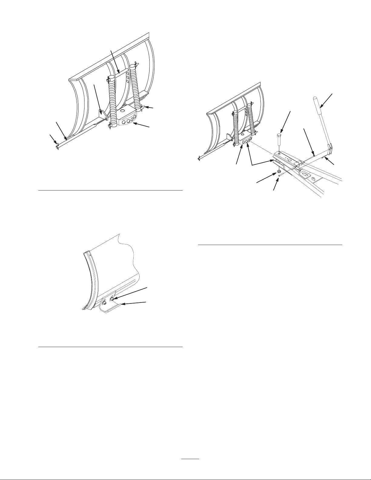
1. Lift and rotate the channel assembly (Fig. 4) so that
the holes align with the lower blade mounts.
2. Slide the rod through the holes and secure it with two
cotter pins (1 inch) (Fig. 4).
5
m–3269
1
3
2
3
4
5
Figure 4
1. Channel assembly
2. Rod
3. Cotter pin, 1 inch
4. Lower blade mounts
5. Upper rod
3. Bend the ends of the cotter pins to secure the rod.
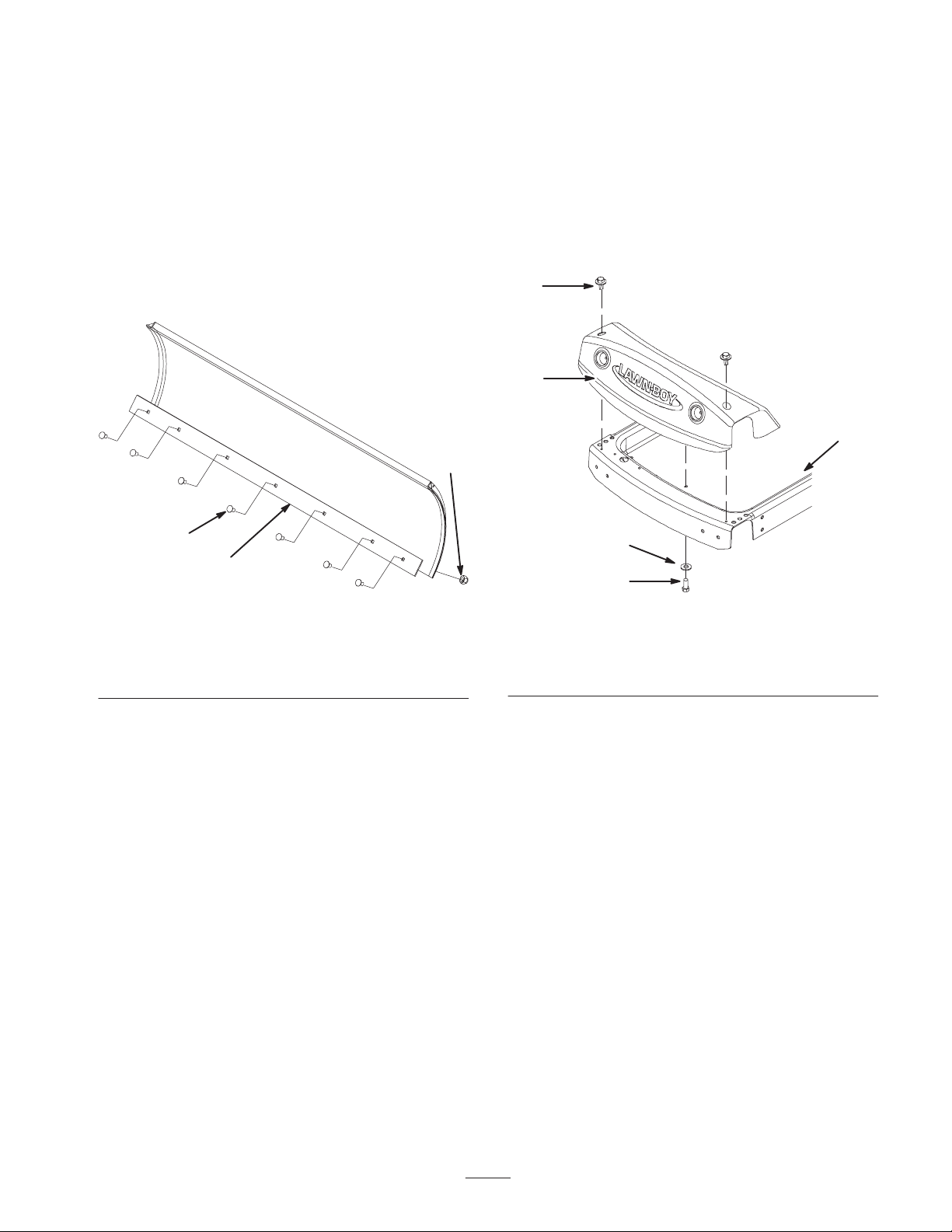
4. Attach the skids to both sides of the blade with 4
carriage bolts (3/8 x 1 inch), flat washers (3/8 inch),
and locknuts (3/8 inch) (Fig. 5).
m–5559
1
2, 3, 4
Figure 5
1. Skid
2. Carriage bolt, 3/8 x 1 inch
3. Flat washer, 3/8 inch
4. Locknut, 3/8 inch
Note: Use the slotted holes to position the skid height
according to what type of surface you will be plowing.
Position the skids lower for plowing rough surfaces or
higher for plowing smoother surfaces.
5. Apply a general purpose grease to the pivot area of the
frame and channel (Fig. 6).
6. Slide the blade channel assembly between the frame
mount and secure it with a bolt (3/4 x 3-3/4 inch) and
locknut (3/4 inch) (Fig. 6).
Note: Do not tighten the nut and bolt excessively; this
avoids binding on the channel weldment as it pivots from
side to side.
m–5567
12
3
4
5
6
7
8
Figure 6
1. Channel assembly
2. Grease here
3. Bolt, 3/4 x 3-3/4 inch
4. Locknut, 3/4 inch
5. Index lever
6. Bolt, 1/4 x 2 inch
7. Locknut, 1/4 inch
8. Cotter pin, 1-1/4 inch
7. Attach the index lever to the frame assembly with a
bolt (1/4 x 2 inch) and locknut (1/4 inch) (Fig. 6).
8. Connect the index lever to the angle pin with a cotter
pin (1-1/4 inch) (Fig. 6).
9. Bend the end of the cotter pin to secure the lever.
6
Preparing the Machine
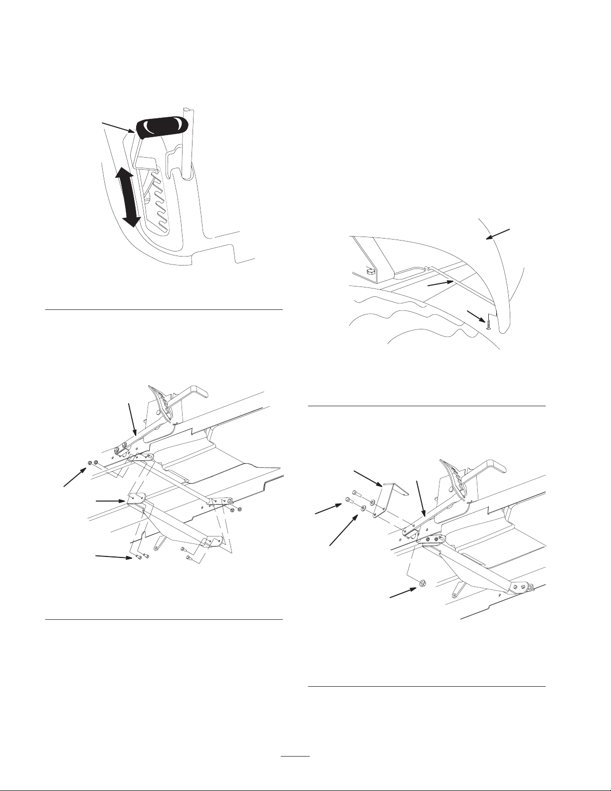
1. Move the lift lever into the lowest position to install
the lift arm (Fig. 7).
1
Figure 7
1. Lift lever
2. Attach the lift arm to the the machine lift arm
assembly using 4 bolts (5/16 x 3/4 inch) and 4 nuts
(5/16 inch) as shown in figure 8. The nuts are to be
installed on the outside to prevent interference when
operating the blade.
2
1
3
4
m–8193
Figure 8
1. Lift arm
2. Bolts, 5/16 x 3/4 inch
3. Locknuts, 5/16 inch
4. Lift lever
Installing the Extension Spring
Note: Machines with Model number 81250 have an
extension spring assembly installed and therefore the
following procedure does not need to be performed.
Please move ahead to Installing the Snow Blade on
page 8.
1. Locate the support rod securing the right side cover to
the machine frame.
2. Remove the screw securing the support rod to the right
side cover.
3. Remove the support rod and retain all parts.
m–8194
1
2
3
Figure 9
1. Right side cover
2. Support rod
3. Screw
4. Remove the 2 bolts, 2 washers, and nut connecting the
lever to the lift block. Discard the 2 bolts and retain
the washers and locknut.
5
2
3
1
m–8195
4
Figure 10
1. Lift arm
2. Bolt, 3/8 x 1-1/4 inch
3. Washer
4. Locknut
5. Front spring mount
5. Attach the front spring mount to the lift lever using 2
bolts (3/8 x 1-1/4 inch) and the washers and locknut
removed in step 4 (Fig. 10).
7
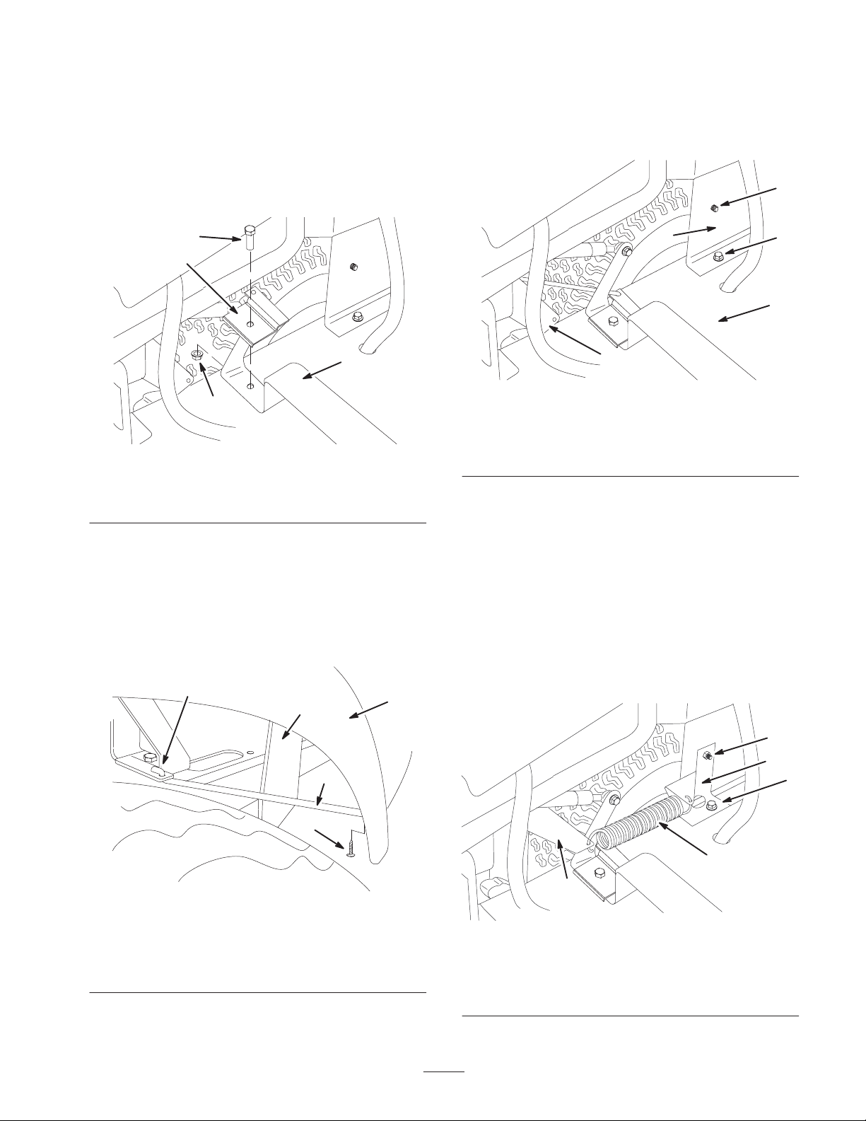
6. Lift the seat forward to access the interior of the
machine.
7. Remove the bolt and locknut securing right side of the
seat brace to the frame. Retain all fasteners
8. Install the support rod bracket over the hole in the seat
brace. Secure the bracket and brace to the frame using
the bolt and locknut removed previously (Fig. 11).
1
2
3
4
m–8196
Figure 11
1. Bolt
2. Bracket
3. Seat brace
4. Locknut
9. Install the support rod into the support rod bracket as
shown in Figure 12.
Note: The orientation of the Z bend in the support rod has
flipped to accommodate the new support rod bracket.
10. Secure the rod to the right side cover using the screw
removed previously.
m–8197
1
2
3
5
4
Figure 12
1. Right side cover
2. Support rod
3. Screw
4. Z bend, flipped orientation
5. Front spring mount
11. Remove the front bolt and nut in the base of the gas
tank plate (Fig. 13). Retain these fasteners.
12. Remove the upper screw in the gas tank plate and
discard (Fig. 13).
3
4
5
1
2
m–8198
Figure 13
1. Tractor frame
2. Gas tank plate
3. Front bolt
4. Upper screw
5. Front spring mount
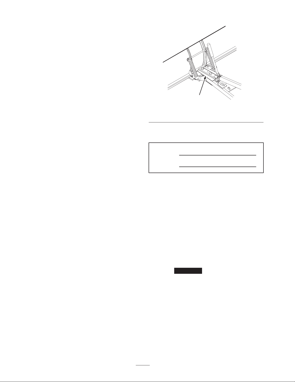
13. Install the rear spring mount to the gas tank plate using
the front bolt removed in step 11 (Fig. 14).
14. Secure the rear spring mount to the gas tank plate
using a bolt (1/4 x 3/4 inch) and locknut (1/4 inch)
(Fig. 14).
15. Raise the lift lever to the highest possible position.
16. Attach one end of the spring to the front spring mount
and the other to the rear spring mount (Fig. 14).
Note: This will require the spring to be partially extended
during this step.
5, 6
1
2
3
4
m–8199
Figure 14
1. Rear spring mount
2. Spring
3. Front spring mount
4. Front bolt
5. Bolt, 1/4 x 3/4 inch
6. Locknut, 1/4 inch

8
17. Lower the seat back into position.
Installing the Snow Blade
1. Attach a side plate to the right side of the machine
frame using 2 bolts (3/8 x 1 inch) and 2 flange nuts
(3/8 inch) (Fig. 15).
Note: Torque the side plate bolts to 30 ft.-lb. (41 N⋅m).
m–7044
1
2
3
4
Figure 15
1. Side plate
2. Bolt, 3/8 x 1 inch
3. Flange nut, 3/8 inch
4. Tractor frame
2. Lift the blade assembly off the ground and slide the
frame assembly beneath the machine as depicted by
the arrows shown in figure 16.
m–8174
1
2
4
3
Figure 16
1. Lift the blade assembly
2. Slide the frame assembly
under the tractor
3. Snow blade assembly
4. Rear shaft
Note: The snow blade is in position when the rear shaft of
the frame assembly has moved past the lift arm and is
lined up with the hole in the side plate.
3. Lift the rear shaft of the frame assembly up and into
the side plate hole (Fig. 17).
m–7046
1
2
Figure 17
1. Rear shaft 2. Side plate hole
4. Install the other side plate on the left side of the unit
over the rear shaft using 2 bolts (3/8 x 1 inch) and 2
flange nuts (3/8 inch).
Note: Torque the side plate bolts to 30 ft.-lb. (41 N⋅m).
5. Remove 2 bolts (1/4 inch), securing the foot plate to
the frame (Fig. 18). Remove the bolt and washer from
under the foot rest. Retain all fasteners.
m–8175
3
1
2
4
5
Figure 18
1. Foot rest
2. Frame
3. Bolt (1/4–20 inch)
4. Washer
5. Bolt (1/4–10 inch)
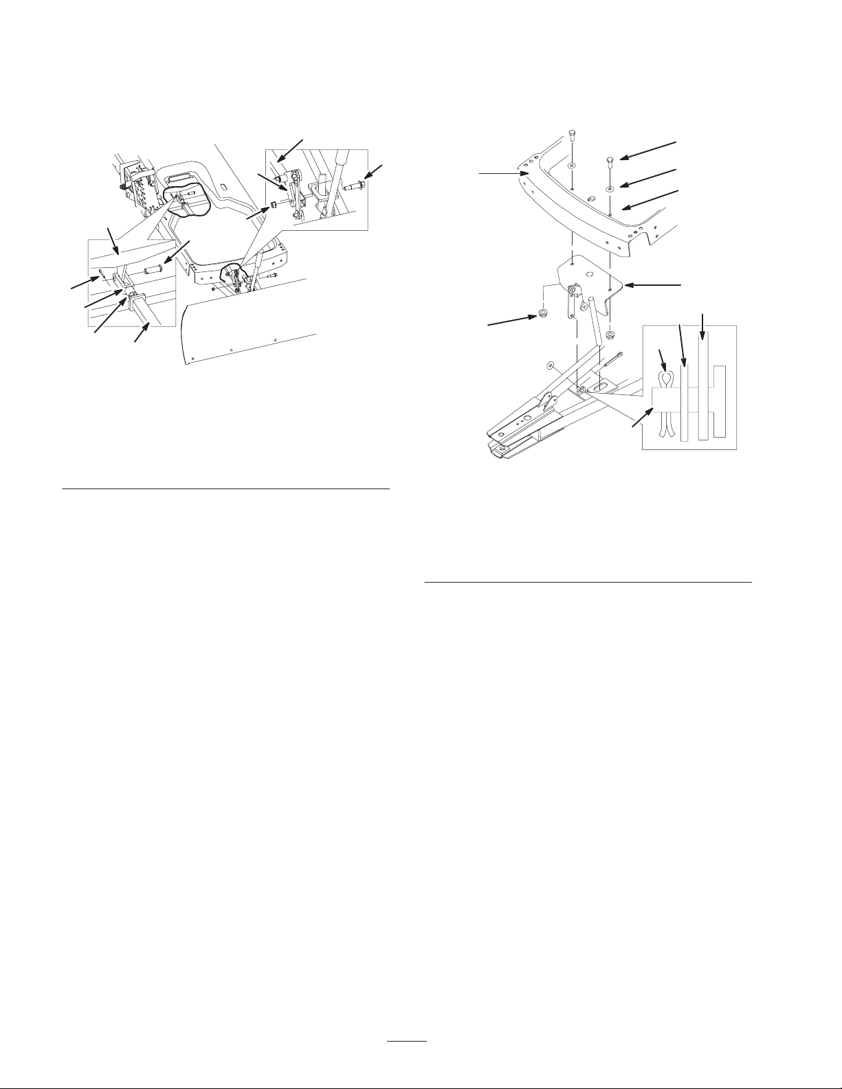
6. Remove the foot plate to access the existing holes in
the machine frame (Fig. 19).

9
m–8176
5
2
4
6
1
3
10 7
8
9
Figure 19
1. Existing hole
2. Bolt, 3/8 x 1 inch
3. Washer, 3/8 inch
4. Flange nut, 3/8 inch
5. Tractor frame
6. Lift mount assembly
7. Lift link
8. Frame assembly post
9. Cotter pin, 3/4 inch
10. Washer, 3/8 inch
7. Install the lift mount assembly using 2 bolts
(3/8 x 1 inch), 2 washers (3/8 inch) and 2 flange nuts
(3/8 inch) as shown in figure 19.
Note: Move the lift mount assembly into position from the
side of the unit in order to install it in the correct
orientation.
8. Place the link lift over the frame assembly post and
use a washer (3/8 inch) and cotter pin (3/4 inch) to
hold it in place (Fig. 19).
9. Bend the end of the cotter pin to secure the lift link.
Connecting the Lift Rod
1. Move the lift rod into position beneath the machine
and above the frame assembly (Fig. 20).
m–7048
1
7
5
1
3
4
9
8
2
6
Figure 20
1. Lift rod
2. Shoulder bolt
3. Flange nut
4. Pivot arm
5. Lift arm
6. Clevis pin
7. Cotter pin, (3/4 inch)
8. Yoke
9. Jam nut
2. Attach the lift rod to the pivot arm of the lift mount
using the shoulder bolt and flange nut (3/8 inch) as
shown in figure 20.
3. Line up the holes in the lift rod yoke and the lift arm
(Fig. 20).
Note: If needed, adjust the length of the lift rod arm by
loosening the jam nut and turn the yoke to either lengthen
or shorten the lift rod.
4. Set the blade height to ensure the full range of motion
with the lift lever. See Setting the Blade Height on
page 11.
5. Install the lift rod to the lift arm using a clevis pin and
cotter pin (3/4 inch) as shown in figure 20.
6. Bend the ends of the cotter pins to secure the clevis
pin.
7. Replace the foot plate with the fasteners removed
previously (Fig. 18).

10
Operation
Important This snow blade should be used for
plowing snow only.
If you hit fixed objects with the blade, the
machine could stop abruptly, causing you to lose
control, sustain personal injury, and equipment
damage.
•Travel at a safe, slow speed.
•Check the area to be plowed and mark all fixed
objects so that you can avoid them.
Caution
Lowering and Raising the
Blade
Use the lift lever to lower and raise the blade (Fig. 21).
To rest the blade on the ground, put the lift lever in the
lowest position.
1
Figure 21
1. Lift lever
Note: Raise the lift lever to highest position when
transporting the blade.
Adjusting the Blade Angle
There are five positions for the side to side angle of the
blade. To change the blade angle, perform the following
procedure:
1. Raise the blade.
2. Push the index lever forward with one hand (Fig. 22)
while positioning the blade with the other hand until
you have reached the desired blade angle.
3. Release the index lever.
Note: The angle pin must snap into the hole in the channel
to retain the blade position.
1
m–5566
Figure 22
1. Index lever

11
Setting the Blade Height
Set the operating height using the following procedure.
1. Move the lift lever into the second lowest position.
2. Remove the cotter pin and clevis pin attaching the lift
rod to the lift arm.
3. Move the lift rod down and out of the lift arm so that
the yoke can turn freely (Fig. 23) and loosen the jam
nut.
m–7052
1
3
2
4
Figure 23
1. Lift rod
2. Lift arm
3. Yoke
4. Jam nut
4. Move lift rod forward as far as possible and hold it in
that position (Fig. 23).
5. Turn the yoke to adjust the length of the lift rod
(Fig. 23). The lift rod is in position when the holes in
the yoke line up with the lift arm.
6. Install the lift rod to lift arm using the clevis pin and
cotter pin removed previously.
7. Bend the end of the cotter pin to secure the clevis pin.
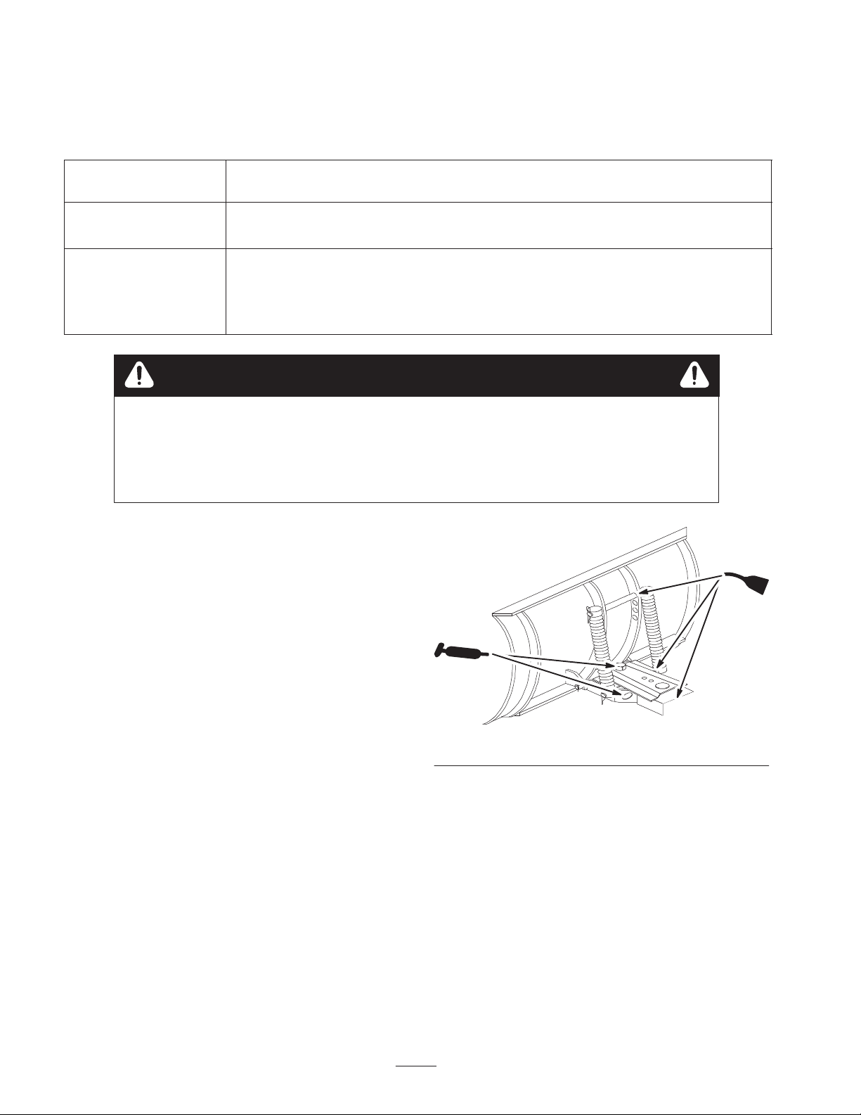
Adjusting the Blade Trip
Springs
The blade trip springs can be mounted in four positions.
The top hole provides the greatest scraping pressure and
the bottom hole provides the least scraping pressure
(Fig. 24).
1. Remove the hairpin cotter and slide the rod from the
blade and springs (Fig. 24).
2. Slide the rod through the springs and the new hole
position in the blade (Fig. 24).
m–3395
1
2
3
4
Figure 24
1. Hairpin cotter
2. Rod
3. Spring
4. Top hole
Tips for Using the Blade
To obtain the best possible results with your blade, follow
these tips:
•Remove snow as soon as possible after it falls.
•Remove snow from a driveway by making one pass
down the center and then plowing snow to either side
on successive passes.
12
Maintenance
Recommended Maintenance Schedule
Maintenance Service
Interval Maintenance Procedure
25 hours
•Grease the channel pivot.
•Oil the linkages.
Yearly/Storage Service
•Grease the channel pivot.
•Oil the linkages.
•Examine the scraper for wear and replace if necessary.
•Paint any chipped surfaces.
Caution
If you leave the key in the ignition switch, someone could accidently start the engine and
seriously injure you or other bystanders.
Remove the key from the ignition and disconnect the wire from the spark plug before you do
any maintenance. Set the wire aside so that it does not accidentally contact the spark plug.
Greasing and Lubricating the
Blade
Grease and oil the blade after every 25 operating hours or
once a year, whichever occurs first.
Grease type: general-purpose grease
Oil type: SAE 10W or 10W30
Greasing the Channel Pivot
1. Lower the blade.
2. Set the parking brake, stop the engine, and remove the
ignition key.
3. Clean the area around the channel pivot with a rag.
Apply grease to the pivot bolt, frame, and channel
indexing holes (Fig. 25).
4. Wipe off excess grease.
m–1473
Figure 25
Oiling the Linkages
1. Set the parking brake, stop the engine, and remove the
ignition key.
2. Place a few drops of oil on all movable linkages
(Fig. 25).
3. Wipe off excess oil.
13
Reversing the Scraper
Periodically inspect the scraper blade for wear. Reverse
the scraper blade when it becomes worn and before the
working surface contacts the housing.
1. Raise the blade and support the housing off of the
ground.
2. Remove the carriage bolts and locknuts securing the
scraper (Fig. 26).
3. Reverse the scraper and install it with the previously
removed hardware (Fig. 26).
m–5568
1
2
3
Figure 26
1. Scraper
2. Carriage bolt
3. Locknuts
Removing the Blade
Note: Retain all parts for installing the snow blade on the
machine in the future.
1. Move the lift lever into the lowest position to remove
the blade.
2. Remove 2 bolts (1/4 inch), securing the foot plate to
the frame (Fig. 27). Remove the bolt and washer from
under the foot rest. Retain all fasteners.
m–8175
3
1
2
4
5
Figure 27
1. Foot rest
2. Frame
3. Bolt (1/4–20 inch)
4. Washer
5. Bolt (1/4–10 inch)
3. Remove the foot plate to access the existing holes in
the machine frame (Fig. 27).
14
4. Remove the shoulder bolt and flange nut (3/8 inch)
attaching the lift rod to the pivot arm of the lift mount
as shown in figure 28.
m–7048
1
7
5
1
3
4
9
8
2
6
Figure 28
1. Lift rod
2. Shoulder bolt
3. Flange nut
4. Pivot arm
5. Lift arm
6. Clevis pin
7. Cotter pin, (3/4 inch)
8. Yoke
9. Jam nut
5. Remove the cotter pin (3/4 inch) and washer (3/8 inch)
securing the lift mount to the frame assembly
(Fig. 29).
6. Remove the clevis pin and cotter pin (3/4 inch)
securing the lift rod to the lift arm (Fig. 28).
7. Remove the lift rod from the machine.
8. Remove the 2 bolts (3/8 x 1 inch), 2 washers (3/8 inch)
and 2 flange nuts (3/8 inch) securing the lift mount
assembly to the tractor frame (Fig. 29).
m–8176
5
2
4
6
1
3
10 7
8
9
Figure 29
1. Existing hole
2. Bolt, 3/8 x 1 inch
3. Washer, 3/8 inch
4. Flange nut, 3/8 inch
5. Tractor frame
6. Lift mount assembly
7. Lift link
8. Frame assembly post
9. Cotter pin, 3/4 inch
10. Washer, 3/8 inch
9. Remove the lift mount from the machine.
Note: Move the lift mount assembly out of position from
the side of the machine.
10. Remove the 4 bolts (3/8 x 1 inch) and 4 flange nuts
(3/8 inch) securing side plates to the tractor frame.
11. Remove the side plates and lower the frame assembly
to the ground.
12. Remove the 4 bolts (5/16 x 3/4 inch) and 4 nuts
(5/16 inch) securing the lift arm to machine.
13. Remove the lift arm.
14. Slide the snow blade assembly out from under neath
the machine.
15. Replace the foot plate with the fasteners removed
previously.

15
Storing the Blade
1. Before long-term storage, wash the entire blade
assembly with mild detergent and water to remove dirt
and grime.
2. Check the condition of the scraper; refer to Reversing
the Scraper Blade, page 13.
3. Grease and oil the blade; refer to Greasing and
Lubricating the Blade, page 12.
4. Check and tighten all bolts, nuts, and screws. Repair or
replace any part that is damaged.
5. Paint all scratched or bare metal surfaces. Paint is
available from your Authorized Lawn-Boy Dealer.
6. Store the blade in a clean, dry garage or storage area.
7. Cover the machine to protect it and keep it clean.

Table of contents
Other Lawn-Boy Snow Blower manuals


