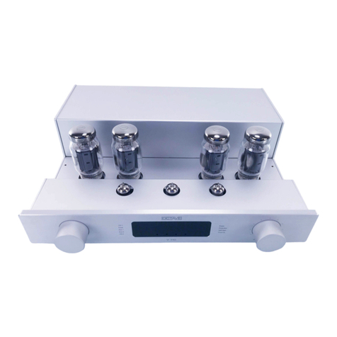
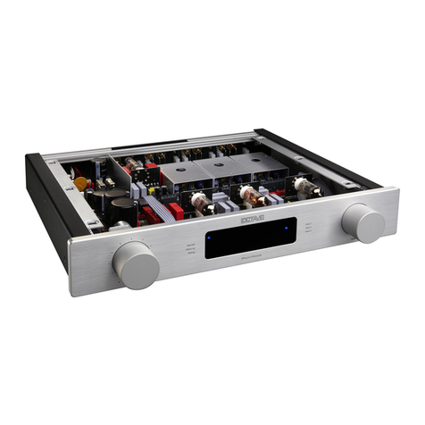
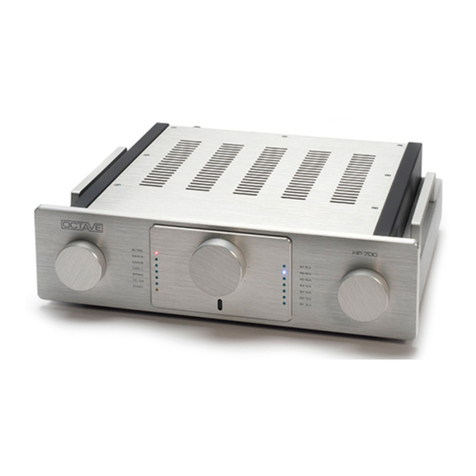
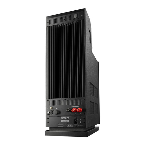
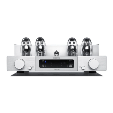
Octave JUBILEE Pre User manual

JUBILEE Pre

1
FOREWORD
I wish to personally thank you for choosing
OCTAVE products and congratulate you on
your purchase of your new
Jubilee preamplifier.
Here at our head office in Karlsbad, right on
the edge of the Black Forest, we have been
designing and building high quality, long-
lasting hi-fi equipment for over 20 years
that will – quite literally – provide you with
hours of musical pleasure for many years to
come.
Today's loudspeakers and high-resolution
source equipment continue to be very
demanding of amplifiers. As a result, achiev-
ing improved amplifier sound quality re-
quires greater levels of technical innovation
than ever before.
OCTAVE specializes in the ongoing devel-
opment of upgradeable circuit designs and
has earned a reputation over recent years
as a world leader in the field of high-end
tube amplifier design. Thanks to our years of
experience and our in-depth understanding
of amplifier technologies and their side ef-
fects, OCTAVE is able to achieve a musical
quality and degree of reliability that seemed
impossible or unaffordable only a few years
ago
I trust that you will enjoy many hours of wonderful music with your
OCTAVE amplifier.
Andreas Hofmann
Chief Designer and Owner of OCTAVE Audio

3
CONTENTS
Page
Foreword ................................................................................................................................1
Contents.................................................................................................................................3
1. Introduction
1.1. What makes OCTAVE amplifiers special ...........................................................4
1.2. Description of the Jubilee preamplifier................................................................5
2. Safety precautions
2.1. Before you begin.................................................................................................6
2.2. Positioning ..........................................................................................................7
3. Operation
3.1. Jubilee preamplifier front panel...........................................................................8
3.2. Jubilee preamplifier top view...............................................................................9
4. Connections
4.1. Rear panel Jubilee preamplifier ........................................................................10
4.2. Rear panel Jubilee power supply......................................................................12
5. Installation ........................................................................................................................13
6. Tubes
6.1. Tube layout.......................................................................................................14
6.2. General information ..........................................................................................15
6.3. Replacing tubes................................................................................................15
7. Service notes
7.1. Troubleshooting................................................................................................16
7.2. Service address................................................................................................17
8. Specification
8.1. Dimensions.......................................................................................................18
8.2. Response Curves .............................................................................................20
8.3. Technical specification..................................................................................... 21

4
1. INTRODUCTION
1.1 WHAT MAKES OCTAVE AMPLIFIERS SPECIAL
Technology
Tubes themselves do not themselves guar-
antee high quality sound. Only by partner-
ing them with innovative electronics de-
signed to create the optimum conditions for
the tubes you can achieve consistently high
sound quality.
OCTAVE amplifiers are equipped with a
power management system whose design
is unique. This electronic monitoring and
protection system is comprised of a soft-
start control and a protection system. An
electronic control module regulates and
controls all the functions of our amplifiers.
When you switch it on, the soft start circuit
ensures that the tube heaters and operating
voltages are ramped up gently. If a fault
should occur, the protection system steps
in to switch the power off virtually instanta-
neously. This intelligent power manage-
ment system guarantees total protection
against all conceivable faults.
An optimized power supply, sophisticated
power supply circuitry and the high load
stability of the output stages ensure that
every power amp and integrated amp bear-
ing the OCTAVE name is capable of devel-
oping its full sonic qualities with virtually
any loudspeaker.
Together, these measures deliver a su-
premely consistent sound quality and a
dependability that is recognized as world
class.
Manufacturing
Every OCTAVE amplifier is 100 percent
"made in Germany". Our products are built
individually by hand and thoroughly tested
before they leave the factory. We design
and make our own custom transformers. We
maintain extremely high quality standards
through close cooperation with specialist
suppliers and by insisting on producing me-
chanical components in house on the latest
CNC machines. The most important contrib-
uting factor, however, is the highly qualified
and enthusiastic team working here at OC-
TAVE. The company owner, Andreas Hof-
mann, retains ultimately responsibility for the
design and development of all OCTAVE
products.
Sound
OCTAVE is fully convinced of the musicality
and sonic superiority of tubes. But our ex-
perience tells us that using tubes does not
automatically lead to audiophile sound qual-
ity. We appreciate that the sound character-
istics of an amplifier are a result of the inter-
action of its component parts. This means
that a high degree of technical skill must be
applied to optimizing every detail in order to
design a reliable amplifier that will maintain
its characteristics over time and that will
convince the critical listener over the long
term that its reproduction of music is both
honest and natural

5
1. INTRODUCTION
1.2 DESCRIPTION OF THE JUBILEE PREAMPLIFIER
Circuit design
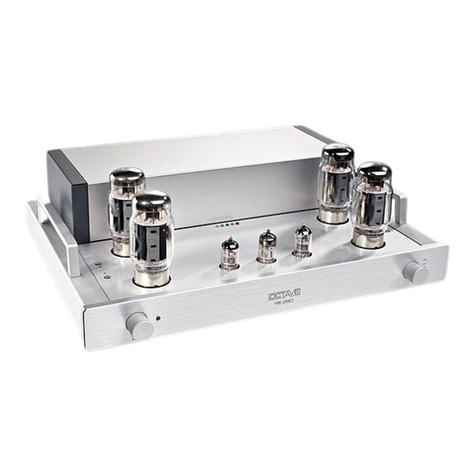
OCTAVE has designed its reference ampli-
fier – the Jubilee preamp – as a two-stage
hybrid amplifier. Tube circuitry manages the
high precision balanced stage and amplifies
the signal. The high output current require-
ments are satisfied by an output impedance
converter implemented with semiconduc-
tors. The unique combination of tubes and
transistors allows the Jubilee to do without
overall negative feedback and thus deliver
the undeniable sonic benefits of a zero
feedback design. However, any amplifier
that dispenses with negative feedback also
dispenses with the corrective mechanism
provided by negative feedback circuitry. In
the Jubilee preamplifier, we solve this prob-
lem through the extremely high specifica-
tion of the output stages and power supply
section, creating virtually perfect conditions
for achieving perfectly accurate amplifica-
tion – without the need for corrective
mechanisms.
Whether the source equipment is con-
nected via the RCA / CINCH phono or XLR
inputs, the Jubilee tube preamp always
produces a perfectly balanced output signal
and delivers an optimum sonic performance
independent of the source type. The XLR
inputs are fitted with step-up transformers
that have no sonic signature of their own.
Because they introduce no noise or phase
shifts, step-up transformers are the tech-
nology of choice for this application in pro-
fessional recording studios. What is more,
they also perform the function of a ground
lift circuit, eliminating the risk of interference
and hum that is particularly critical when
dealing with complex multi-amp rigs con-
nected via balanced inputs.
The low impedance output is yet another
feature designed to enhance the sound
quality and versatility of the Jubilee pream-
plifier. Only a semiconductor-based output
stage is able to cope with long cable runs
and integrate perfectly with low impedance
power amplifiers
It would be impossible to implement such an
uncritical output using tubes alone without
sacrificing accuracy in the low bass and
extreme high frequencies.
Outboard power supply
The outboard power supply, which was de-
veloped exclusively for the Jubilee preampli-
fier, substantially enhances the sound qual-
ity of the preamp by separating the pream-
plifier from the mains (simulated battery
operation). The separate power supply stops
noise pollution from entering the preamp's
signal processing circuitry. It also provides
highly accurate and stable electronic voltage
regulation, which is one of the ways we en-
sure this product's consistent performance
over time.
The Jubilee's sophisticated power manage-
ment system guarantees a long and reliable
life and incorporates highly refined soft-start
technologies that help the tubes achieve
their theoretical maximum service life of up
to 50,000 hours.
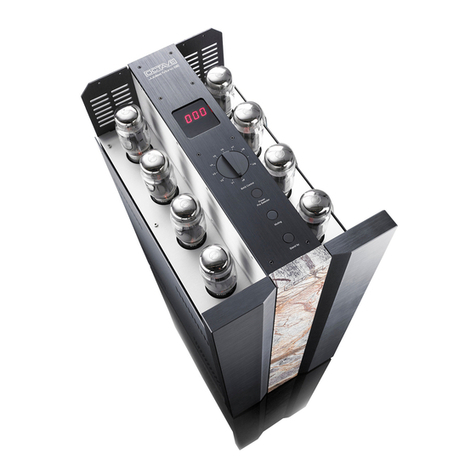
Build quality
The volume control with its precision ball
bearings is centrally placed within a polished
Labrador natural stone slab, flanked by two,
three-centimetre thick, solid aluminium pan-
els. The extremely stable, low resonance,
all-aluminium casing eliminates any possibil-
ity of magnetic distortion. Before leaving the
factory, each hand-built Jubilee preamplifier
is thoroughly inspected and subjected to a
48- hour soak test
6
2. SAFETY PRECAUTIONS
2.1 BEFORE YOU BEGIN
Read the instructions before switching
the unit on.
Please read through this manual carefully
before switching on your amplifier and pay
particular attention to the safety instructions.
Please keep this manual safe for future ref-
erence and retain the original packing to use
whenever your amplifier is transported.
In case of emergency: disconnect the
plug from the mains supply
Never use an amplifier that is damaged or
faulty. Make sure that it cannot be used until
it has been repaired by a qualified service
engineer. You should also remove the mains
plug if you expect not to use the amplifier for
a long period.
Do not open the case
There are dangerously high voltages and hot
tubes inside this equipment. To avoid a burn
or the risk of electric shock, never allow
anyone except qualified personnel to open
the case.
Servicing and maintenance
To avoid the risk of any other hazards, ser-
vicing, repairs and other modifications to this
OCTAVE equipment should only be carried
out by qualified personnel. Always replace
fuses with ones of the same type and rating.
If your amplifier requires servicing, please
ship or take your equipment directly to OC-
TAVE or to one of our authorized service
centres.
Explanation of the symbols
The lightning flash with arrowhead symbol
within an equilateral triangle is intended to
alert the user to the presence of uninsulated
'dangerous voltages' within the product's
enclosure that may be sufficient to constitute
a risk of electric shock to persons.
The exclamation point within an equilateral
triangle is intended to alert the user to im-
portant operating and maintenance instruc-
tions.
The CE mark certifies that this electrical
equipment complies with current European
Union product safety regulations such as
the Low Voltage Directive and the Electro-
magnetic Compatibility Directive.
Before connecting up
The Jubilee preamplifier is designed to
operate exclusively with the power supply
supplied. Make sure before connecting the
power cord that your amplifier is suitable
for your local supply voltage.
Protection class
In Japan this amplifier is a protection class
2, no earth connector. In other countries it
is a protection class 1 device (with protec-
tive earth conductor).
Adjusting the volume
While you are setting your amplifier up,
turn the volume control anticlockwise, close
to the minimum setting. High sound pres-
sure levels can damage to your hearing as
well as your loudspeakers.
Safety warning: Hot tubes
Tube equipment gets very hot and takes
about 20 minutes to cool down after you
have switched it off. The exterior of the
case, which can also heat up during normal
operation, and the protective grill fitted over
the external tubes are designed to protect
children and others from being burned
should they ever touch the hot tubes.
Warning: Remove the protective grill at
your own risk. OCTAVE accepts no re-
sponsibility for injuries caused by the re-
moval of this grill.
Warranty
OCTAVE can only guarantee the safety,
reliability and performance of this unit if
modifications and repairs are carried out by
specialized personnel and if the amplifier is
operated in accordance with the instruc-
tions contained in this manual.

7
2. SAFETY PRECAUTIONS
2.2 POSITIONING
1. Location
OCTAVE equipment is designed strictly for
use in a dry domestic environment and
should never be used in the open air or in
damp rooms.
Never place plants or liquid filled objects
such as bottles or glasses on your OC-
TAVE equipment. Take care that objects do
not fall or liquids are not spilled into the
enclosure. Should this happen, remove the
mains plug immediately and have your
amplifier checked by a qualified service
technician.
Condensation may form if the equipment is
taken from a warm environment into a cold
one. In this case, wait until the room has
warmed up before switching the amplifier
on.
Avoid installing the unit close to sources of
heat such as radiators or anywhere that it
may be in direct sunlight. Do not operate
the unit near flammable materials, gases or
vapours. Avoid areas where there may be
heavy accumulations of dust or where the
unit may be subject to mechanical vibration.
2. Level, stable base
Place your OCTAVE amplifier on a stable,
even surface. Special hi-fi equipment sup-
ports can be beneficial.
3. Good ventilation
Make sure that your amplifier has a good
flow of air around it. If you intend to install
your equipment in a cupboard or a shelf,
ensure that there is at least a two centimetre
gap between the ventilation slots and the
bottom of the shelf and a 20 centimetre gap
between each of the walls. The rear panel of
cupboards should have ventilation holes to
prevent heat build up. The equipment should
not be placed on a soft surface such as car-
pet or foam sheeting.
4. Hum
Encapsulated transformers reduce the affect
of magnetic interference on cables and other
hi-fi components such as CD players or
tuners. Nevertheless, you should not place
any other electronic components directly on
or below your OCTAVE equipment.
You should always keep sensitive input cir-
cuitry well away from amplifier power sup-
plies. The mains transformer is located on
the left hand side of most audio equipment.
The input circuitry on OCTAVE amplifiers is
located directly behind the inputs.
5. Power supply
Do not position the Jubilee's power supply
directly on or next to the preamplifier. You
should also avoid placing any equipment
containing sensitive input circuitry, such as a
phono preamp, close to the power supply
(see Section 4. Hum)
Power
supplies
in hi-fi
equipment

8
3. OPERATION
3.1 JUBILEE PREAMPLIFIER FRONT PANEL
The Jubilee preamplifier is equipped with a
delay timer function that helps conserve
tube life. The output is muted (muting LED
illuminates) for six minutes during the start
phase
The muting function is also activated when
the gain switch
4
is used (See Sec. 3.2.)
MODE SELECTOR KNOB
Operate
Is the outboard power supply switched on,
the Operate LED illuminates the correct
work of the power supply. This LED needs
2 minutes delay. When the Muting LED
switches off, the amplifier is ready for use.
Tape 2
Playback of recorder connected to the Tape
2 input
Tape 1
Playback of recorder connected to the Tape
1 input
Source
Playback of the source that has been se-
lected with the input selector knob
3
When the Mode Selector is set to Source,
you can record the source you are listening
to via the two tape outs (Tape 1, Tape 2). To
do this, Tape Copy
6
must be switched off
(see Section 3.2).
Muting
You should mute the preamplifier outputs by
Connecting turning the knob to the Muting
position (LED illuminates) before connecting
or disconnecting source equipment. The
muting switch allows you to do this without
having to switch the Jubilee preamplifier off.
2
VOLUME CONTROL
Turn the volume control anticlockwise near
to its zero position (close to 8 o'clock) before
switching on. High sound pressure levels
can damage your hearing as well as your
loudspeakers
3
INPUT SELECTOR KNOB
(SOURCE)
Selects the input sources Phono, Tuner,
Aux, CD and CD Sym (balanced XLR in-
put). See also Connections on page 10.
Switch-on
delay timer
Connecting
components
Turn the
volume control
down before
using the
p
reamplifier

9
3. OPERATION
3.2 JUBILEE PREAMPLIFIER TOP VIEW
4
GAIN
Facility for switching between high (H) and
low (L) gain. The appropriate LED illumi-
nates to show which position is active.
H (HIGH) position:
This is the standard position for the majority
of power amplifiers and loudspeakers.
L (LOW) position:
A lower gain setting is recommended only
when high efficiency speakers such as
horns are being used.
When switching between gain settings, the
muting function is activated to prevent
switching noises being sent to your ampli-
fier and loudspeakers. The outputs are
restored after a short time. (The muting
LED turns off.) The gain and phase
switches should not be operated at the
same time or immediately after each other,
as this could cause cracking noises through
your system.
5
PHASE SWITCH
Phase switching of the output signal (0 and
180 degrees) applies to both the balanced
XLR and the RCA / CINCH phono outputs.
LED on: 180 degrees phase shift
LED off: 0 degrees phase shift
6
COPY (tape copy function, tape to
tape)
LED on: Tape Copy on
LED off: Tape Copy off
Copying can be carried out from Tape 1 to
Tape 2 and vice versa. Select the copy di-
rection with pushbutton switch
7
(2->1 or
1->2).
7
Tape Copy direction
2 —>1 (LED illuminated)
Tape 2 is the source; Tape 1 is recording
1 —> 2 (LED illuminated)
Tape 1 is the source; Tape 2 is recording
You can monitor your recordings (off-tape)
with the mode selector knob in positions
Tape 1 or Tape 2
Gain
selection
Off-tape
monitoring

10
4. CONNECTIONS
4.1 REAR PANEL JUBILEE PREAMPLIFIER
General points: The following applies to all connections:
L (LEFT): left stereo channel, R (RIGHT): right stereo channel
XLR pin connections: 1: GROUND, 2: + (hot) 3: — (cold)
8
RC
Connector for the infrared receiver. The
remote control is optional
9
CD SYM Section
Line level XLR input for sources with bal-
anced outputs (CD player)
The INPUT MODE switch CD SYM allows
to switch the CD XLR input between bal-
anced (XLR) and unbalanced mode.
10
PHONO Section
An additional line level input with the option
of XLR or RCA / CINCH inputs that you can
use to connect sources such as an external
phono preamplifier.
The INPUT MODE switch allows to switch
from balanced (XLR) to unbalanced (RCA /
CINCH) mode. Both of these inputs are
wired in parallel.
Please note that only one line level phono
input (either XLR or RCA / CINCH) can be
used at a time.
The PHONO inputs are not suitable for use
with a turntable without an external phono
preamplifier.
GND (GROUND)
Additional ground connection for external
units like phono preamp and so on
11
GROUND LIFT XLR-INPUTS
Ground lift switch for XLR inputs
Switch position:CONNECT TO GROUND:
Connects the XLR ground to chassis ground
(see Section 7.1 Troubleshooting: hum on
XLR input)
Switch position: DISCONNECT
Disconnects the XLR input ground from the
output ground
In true balanced operation, the ground con-
nection is not necessary, since it does not
carry a signal. Lifting the ground will help
keep out unwanted noise and interference in
balanced operation. If you have source
equipment fitted with a separate earth, you
should also use the DISCONNECT position
to avoid ground loop problems.
Channe
l
orientation
Phono
inpu
t
Ground
connections
in balanced
operation

11
4. CONNECTIONS
4.1 REAR PANEL JUBILEE PREAMPLIFIER
(Power amplifiers are also normally
grounded.) If the INPUT MODE switch is in
the ASYM position, XLR inputs are con-
nected by default; GROUND LIFT does not
work for this input.
12
Phono preamp inputs (RCA/CINCH)
These inputs are active in the PHONO
INPUT MODE ASYM setting. The RCA /
CINCH inputs are wired in parallel to the
balanced (XLR) inputs. You can therefore
use either the RCA / CINCH or the XLR
sockets to connect a phono preamplifier.
13
Tuner input (RCA / CINCH)
Additional line level input for a radio tuner
14
AUX input (RCA / CINCH)
Additional line level input for other sources
such as a video recorder or a television.
15
CD input (unbalanced RCA / CINCH)
Additional input for CD player
16
Tape inputs/outputs
Analogue inputs/outputs for two recording
devices (cassette, DAT or CD recorder)
Tape 2 REC
Output (record) Tape 2
Tape 2 PLAY
Input (replay) Tape 2. With option BYPASS
tape 2 play is the bypass input. Gain from
bypass to RCA out is 0 dB for gain low and
+ 6 dB for the balanced outputs.
Tape 1 REC
Output (record) Tape 1
Tape 1 PLAY
Input (replay) Tape 1
Outputs (2 x RCA / CINCH / XLR)
Output to power amplifiers in unbalanced
mode via the RCA / CINCH sockets or in
balanced mode via the XLR sockets.
17
RCA / CINCH outputs
Two sets of output sockets for connecting to
two separate power amplifiers with unbalan-
ced inputs (RCA / CINCH)
18
XLR outputs
Two sets of XLR output sockets for connect-
ing to two separate power amplifiers with
balanced inputs.
19
Special power connector for the out-
board power supply

12
4. CONNECTIONS
4.1 REAR PANEL JUBILEE POWER SUPPLY
21
Mains Power connection
Before plugging the power cord into the
wall socket, make sure that your amplifier is
suitable for your local supply voltage.
Check the information on the rear of the
Jubilee power supply
23
.
To exclude the risk of electric malfunction,
connect the power supply with the Jubilee
preamp
24
before you connect the power
supply to the mains.
22
Fuse holder
Warning: Fuses should be changed only by
a qualified technician.
Fuses must be replaced with ones of the
same type and rating (refer to markings on
original fuse) You will find further informa-
tion in the Specifications section 8.3. or on
the rear of the power supply
24
Connecting cable from the power
supply to the Jubilee preamplifier
Please switch off the power supply before
connecting this cable to the preamp. Ob-
serve the anti-rotation lug and take care not
over tighten the coupling ring.
Main
s
connection
replacin
g
fuse
s
Before con-
necting up:
switch off the
p
ower supply
20
Remote control for the Jubilee
power amplifiers
Remote switching of the mains power of the
Jubilee amps.
Connector: 6,3 mm jack plug (mono)

13
5. INSTALLATION
1. In your own interest, please observe the
Safety Precautions in Section 2.1 and the
Positioning advice in Section 2.2.
2. Before connecting your OCTAVE ampli-
fier, switch off all other hi-fi equipment. This
will avoid possible problems when you
connect your other components to the pre-
amp.
3. Connect your source components such
as CD player, a phono preamplifier, a tuner
and one or two recording devices. You will
find advice on connecting your source
components and information on pin con-
nections in Section 4.1.
Connect the cables from your signal
sources such as CD player to the appropri-
ate inputs (XLR or RCA / CINCH phono) on
your Jubilee preamplifier. Also, connect the
Record Out of recording equipment to the
tape inputs on your Jubilee preamplifier.
4. Connect the leads from your Jubilee
preamplifier (XLR or RCA / CINCH) to the
appropriate inputs on your power amplifi-
ers.
Make sure that the power supply is
switched off before you connect the power
supply cable.
When inserting the connector, observe the
anti-rotation lug and take care not over
tighten the coupling ring.
5. Turn the volume control anticlockwise
close to the minimum setting. Remember
that high sound pressure levels can dam-
age to your hearing as well as your loud-
speakers.
6. Connect the power supply to the wall
socket. Plug the power cord
24
of the Jubi-
lee power supply into the special socket
on the preamplifier.
19
Jubilee power supply front:
Power Supply
25 26
7. Switch the power supply on (switch
26
).
LED
25
on the front panel of the power sup-
ply will illuminate
Wait until the Muting LED on the Jubilee
preamplifier goes out. The unit will be ready
for use in about six minutes.
8. Now you can adjust the settings (GAIN,
PHA-SE etc.) as described in Section 3.
9. Switch your other components on.
10. Select a source using input selector
knob
3
and adjust the volume to your nor-
mal listening level.
11. Running in
Tube equipment generally takes about three
months to run in and start sounding its best.
Daily use is useful during this period but it is
not necessary to leave the equipment on
continuously, as this does not greatly reduce
the running-in time.
12. Please keep this manual safe for future
reference and retain the original packing for
use whenever your amplifier is transported.
Connectin
g
the powe
r
suppl
y
Reduce
volume
Running in

14
6. TUBES
6.1 TUBE LAYOUT
Tube complement
27
,
28
,
29
30
sockets:
All sockets are fitted with
ECC 82 family
tubes.
The ECC 82 tube is also known as: E82CC,
ECC802S, 12AU6, 5814, 6189W
Sockets
29
and
30
require selected,
matched tubes with equal systems. The
systems of tube
27
+
28
must be
matched to less than 5%
In position
27
the use of the genuine spe-
cial tube E80CC is allowed. The use of this
tube is only in this position practical !
31
Automatic discharge LED (red)
LED on:
When the amplifier has been switched off,
this LED remains lit until the power supply
capacitors have been discharged.
LED off
The power supply capacitors are dis-
charged. If disconnected from the mains
supply, there are no dangerous voltages
present inside the equipment

15
6. TUBES
6.2 GENERAL INFORMATION
Tube life
Thanks to the protection circuits and soft-
start electronics, you can expect your out-
put tubes to last for an average of five
years.
Differences in tube service life
Faulty tubes can be replaced individually. It
is not necessary to replace an entire set.
Running in
New tubes can require a relatively long time
(up to 300 hours) to achieve their optimum
sound quality.
Faulty tubes
Manufacturing faults in tubes may only be-
come evident after about 100 hours of use.
You should therefore be wary of installing
untested tubes. However, faulty tubes or
tubes of the incorrect type will normally not
damage the amplifier. Nevertheless, they
may cause loud crackling noices in your
loudspeakers.
6.3 REPLACING TUBES
1. For safety reasons, only qualified per-
sonnel should open the amplifier and re-
place the tubes.
2. Switch off the preamplifier, unplug the
power cord from the wall socket and allow
the unit 10 minutes to cool down.
3. The Jubilee's automatic discharge sys-
tem will discharge the power supply capaci-
tors. The red LED
31
will be lit during this
time (see Tube Layout, Section 6.1). To
avoid an electric shock, wait until this LED
has extinguished before opening the case.
4. Remove the acrylic cover and the right
stainless steel lid above the input selector
knob
3
.
5. Take out the old tubes
Carefully remove the tubes from their sock-
ets, taking care not to exert sideward-
pressure on the sockets.
6. Fit new tubes
Please only use original OCTAVE replace-
ment tubes. These have been tested and
selected for use in our amplifiers.
Please ensure that the tube pins are all
perfectly straight before inserting your new
tubes. Straighten any bent pins very
carefully by hand if necessary. No adjust-
ments are necessary to your amplifier after
fitting new tubes.
7. Cleaning tips
Cleaning agents and contact cleaners are
not recommended for tube sockets. Clean
dirty sockets with compressed air and clean
dirty tube pins carefully using a wire brush.
A toothbrush dipped in isopropyl alcohol
also works well.

16
7. SERVICE NOTES
7.1 TROUBLESHOOTING
Amplifier will not switch on
POSSIBLE CAUSES
> The Jubilee power supply power cord is
loose or not connected correctly
> No or faulty power connection between
preamp and power supply
> Blown fuse in the Jubilee power supply
REMEDY
> Connect power cord and check the wall
socket and power connections
> Check the connection of the power cord to
the wall socket and the power cord between
the Jubilee power supply and preamp
> Have a qualified service engineer check
your equipment and replace the fuses (iden-
tical rating and type!)
Preamp turns on, but no sound
POSSIBLE CAUSES
> Amplifier has only recently been switched
on or the gain switch has been operated
> The Jubilee preamplifier has muted (Mut-
ing LED illuminated) or the volume control
is turned down
> Input selector knob or mode selector
knob not set correctly
> Power amplifiers or source equipment not
switched on or not in play mode
> Problem with the installation: faulty leads
between source equipment and/or power
amplifier and the Jubilee preamplifier
REMEDY
> Wait until the preamplifier has warmed up
(about. 6 minutes) and the Operate LED is lit
> Deactivate Muting on the Mode Selector
knob (LED will extinguish) or slowly turn
up the volume with volume knob 2.
> Check the setting of the Input Selector
3
and Mode Selector knob .
> Switch on power amplifiers. Switch on
source equipment and play some music
> Check leads and connections and correct
faults
Humming and crackling
POSSIBLE CAUSES
> The connecting lead phono plugs are not
making a proper connection to ground
> Inadequate contact between the phono
plug's signal pin and the phono socket
> Hum on XLR input
REMEDY
> Check your interconnect cables and make
sure that phono plugs are a tight fit. If the
plugs appear loose, you can try bending the
ground contacts (on the outside of the plug)
in slightly.
> Try another interconnect or, if necessary,
have the RCA / CINCH phono sockets re-
placed by the OCTAVE service department.
> GROUND LIFT XLR INPUTS
11
(See
Connections in Sect. 4.1) in DISCONNECT
position. Lifting the ground helps to prevent
unwanted noise in balanced operation.

17
7. SERVICE NOTES
7.1 TROUBLESHOOTING
Cracking noises when switching on and off
POSSIBLE CAUSES
> Household electrical equipment such as
older refrigerators or 12-volt halogen light-
ing systems can generate strong radio
interference when they switch on and off.
This electrical interference can cause an
audible crack or pop through the speakers.
REMEDY
> Connect your hi-fi system to a central
mains distribution board plugged into a wall
socket. Do not connect any other electrical
equipment either to the board or socket.
Volume imbalance between the left and right channels
POSSIBLE CAUSES
> Damaged cables and poorly fitting phono
plugs can create resistance in the signal
path, which can cause one channel to
sound louder than the other.
> Recording equipment (reel-to-reel, cas-
sette, CD or DAT recorder) with a faulty
input or lead can overload the output and
cause an imbalance between the left and
right channels.
REMEDY
> Change the lead, clean plugs and sockets
with isopropyl alcohol.
Warning: Do not use contact cleaning
sprays.
> To isolate the cause of the problem, dis-
connect your recording device(s) one at a
time. Check the interconnect cables used for
recording and renew them if necessary. If
you still have not alleviated the cause of the
problem, have your recording equipment
checked for faults.
Increased hiss on one channel
POSSIBLE CAUSES
> Hiss that varies in level is a sign of a
faulty or worn driver tube.
REMEDY
> You must replace the tube that is causing
the problem. Return the amplifier to us. We
will also gladly ship replacement tubes. You
will find important instructions on replacing
tubes in Section 6.1.
Please note:
OCTAVE offers a 12-month warranty on
tubes.
7.2 SERVICE ADDRESS
If none of these service tips have helped
because your problem is not included here,
please contact your OCTAVE dealer or mail
our Service Support directly.

18
8. SPECIFICATION
8.1 DIMENSIONS OF CASE IN MM
POWER SUPPLY, FRONT VIEW
152
22
0
Power Supply
POWER SUPPLY, SIDE VIEW
480
ca
530
152

19
8. SPECIFICATION
8.1 DIMENSIONS OF CASE IN MM
JUBILEE PREAMPLIFIER, FRONT VIEW
JUBILEE PREAMPLIFIER, SIDE VIEW
480
ca
560
152

20
8. SPECIFICATION
8.2 RESPONSE CURVES
Frequency response
60m
10
100m
200m
500m
1
2
5
V
1
0
2
00
k2
0
50
1
00
2
00
500
1k 2k
5
k1
0
k2
0
k
50
k1
00
kH
z
Extremely linear frequency response. No drop in level at
lowest bass frequencies.
Distortion spectrum
-180
-60
-170
-160
-150
-140
-130
-120
-110
-100
-90
-80
-70
dB
30
2
0
k
50
1
00
2
00
500
1k 2k
5
k1
0
kHz
Distortion spectrum at 1 kHz: only second harmonic k2 is discernible;
no residual hum at 50/100Hz.
Table of contents
Other Octave Amplifier manuals

Octave
Octave V110 User manual

Octave
Octave V 70 Class A User manual

Octave
Octave v70se User manual

Octave
Octave V70 User manual

Octave
Octave JUBILEE Mono User manual

Octave
Octave HP 300 MK2 User manual

Octave
Octave JUBILEE MONO SE User manual

Octave
Octave V 110 SE User manual

Octave
Octave Phono Module User manual

Octave
Octave V 80 SE User manual

Octave
Octave Black Box User manual

Octave
Octave HP500MK3 User manual

Octave
Octave HP 300 SE User manual

Octave
Octave V 16 Single Ended User manual

Octave
Octave Phono EQ.2 User manual

Octave
Octave RE 280 MK2 User manual

Octave
Octave Phono Module User manual

Octave
Octave Super Black Box User manual

Octave
Octave V 50 MKII User manual

Octave
Octave HP 700 User manual