lb display Series User manual
1
Operation Manual
Display Speakers and Soundbars
2
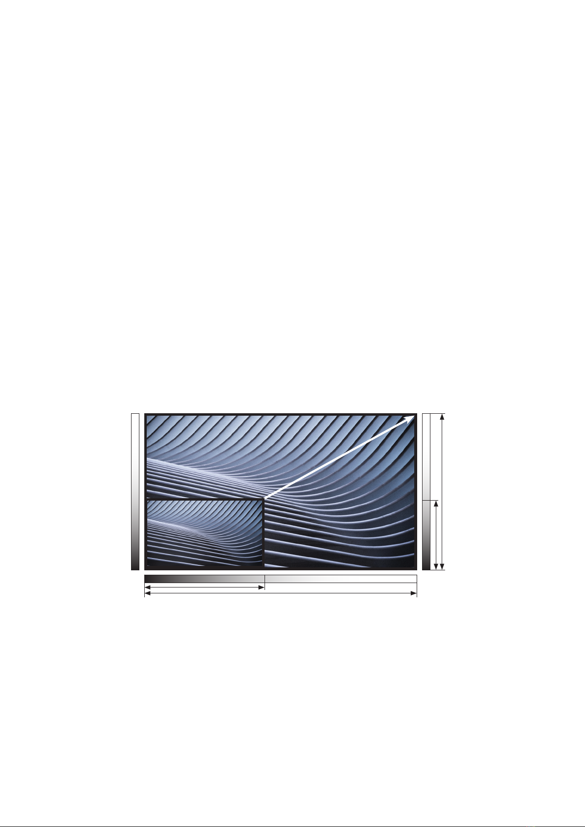
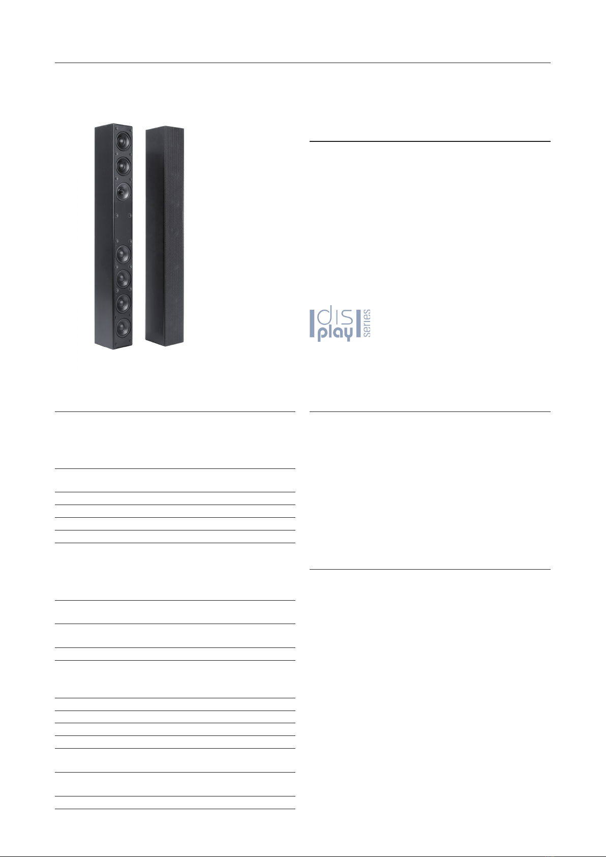
Customized Versions with Made-to-Measure Dimensions
We manufacture special versions of our display speakers and soundbars
tailored to the specic dimensions of individual display models. The
display and speakers harmonize perfectly to create uniform visual units.
Individual Soundbars with a Width from 960 mm to 2350 mm
Individual Display
Speakers with a Height
from 700 mm to 1600 mm

3
Content
1. Important Safety Informations .......................................................................................................................................... 4
2. Connection with DL-A-/SB-A-Speaker Systems to Displays or Players ...................................................................... 5
3. Display Speakers ............................................................................................................................................................... 6
3.1. DL-A 2.0 Active Stereo Display Speaker Pair with DSP ................................................................................................ 6
3.2. DL-A 2.2 Active Stereo Display Speaker Pair with DSP and Integrated Subwoofers ................................................ 8
3.3. DL 2.0 Passive Stereo Display Speaker Pair ................................................................................................................. 10
4. Mounts for Display Speakers ........................................................................................................................................ 12
4.1. DL-VESA Technical Data ................................................................................................................................................. 14
4.2. DL-VESA Assembly with DL-A 2.0 / DL 2.0 ..................................................................................................................... 16
4.3. DL-VESA Assembly with DL-A 2.2 .................................................................................................................................. 17
4.4. WH 80 Wall-Mount Technical Data ............................................................................................................................... 18
4.5. WH 80 Wall-Mount Assembly ......................................................................................................................................... 18
4.6. SH 50 Pivotable Wall-Mount Technical Data ................................................................................................................ 19
4.7. SH 50 Pivotable Wall-Mount Assembly ..........................................................................................................................19
5. Soundbars ......................................................................................................................................................................... 20
5.1. SB-A 2.0 Active Stereo Soundbar with DSP ..................................................................................................................20
5.2. SB-A 2.0 CAM (+) Active Stereo Soundbar with Integrated Camera or with Camera + Microphone Array .......... 22
5.3. SB-A 2.2. Active Stereo Soundbar with DSP and Integrated Subwoofers ................................................................ 24
5.4. SB 2.0 Passive Stereo Soundbar .................................................................................................................................... 26
6. Mounts for Soundbars ..................................................................................................................................................... 28
6.1. SB-VESA Technical Data ................................................................................................................................................. 28
6.2. SB-VESA Assembly with SB-A 2.0 / SB-A 2.0 CAM (+) / SB 2.0 ................................................................................... 30
6.3. SB-VESA Assembly with SB-A 2.2 ................................................................................................................................. 33
6.4. WH 80 Wall-Mount Technical Data ................................................................................................................................ 34
6.5. WH 80 Wall-Mount Assembly ......................................................................................................................................... 34
7. Model Overview .............................................................................................................................................................. 35
Important Safety Information
CAUTION!
Service and repair work must only be carried out by quali ed personnel. Do not open the case as
there is a risk of electric shock. There are no controls or components inside the device that require
you to open the case. If the case has to be opened by quali ed personnel, make sure that the device
is completely disconnected from the power supply.
The operating voltage must match the local power supply.
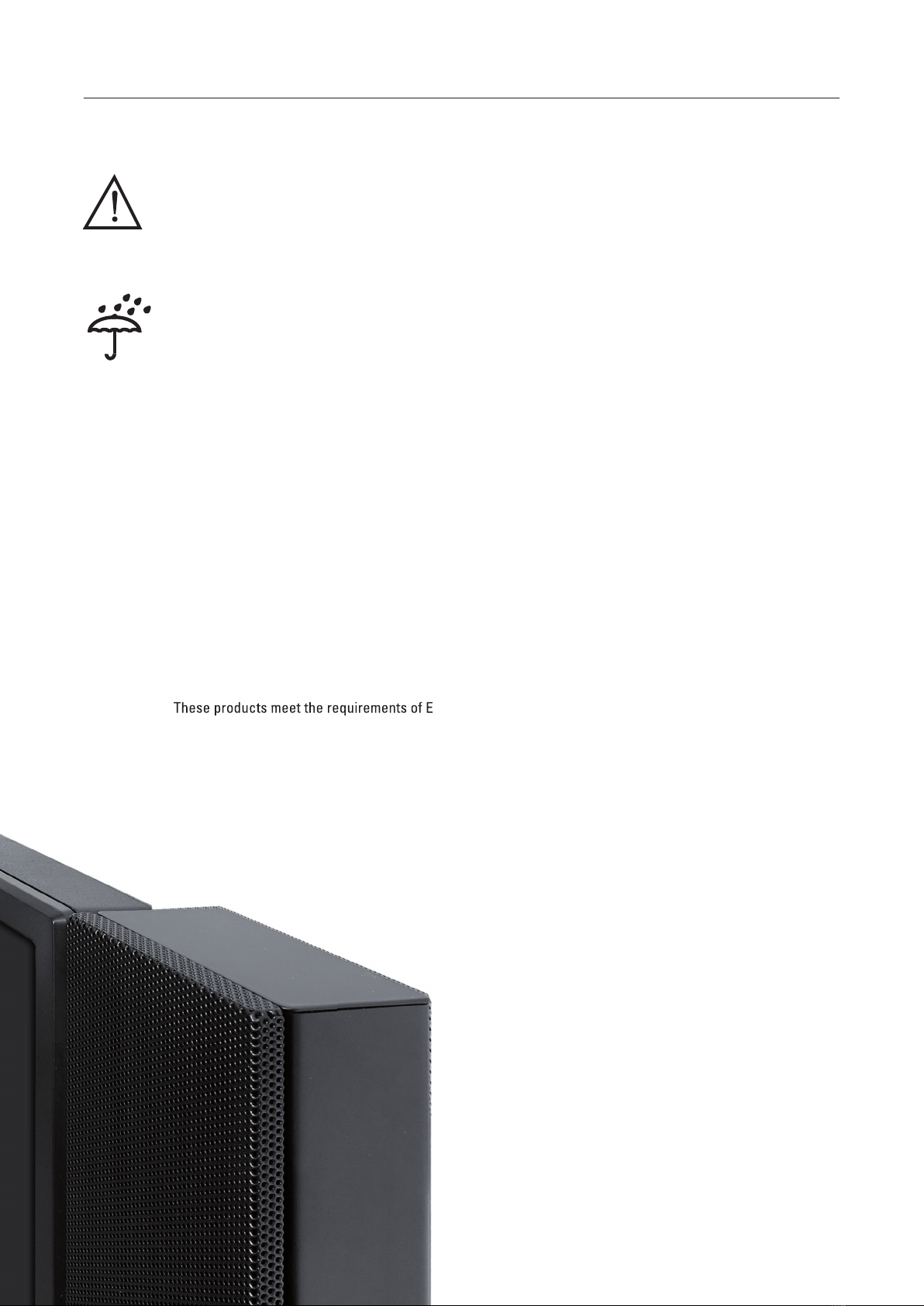
The device should be shielded from moisture and wet conditions. It must not be operated in rain or close
to water, baths, washbasins, sinks, swimming pools or in damp environments. Do not place any objects
lled with water such as vases, glasses or bottles on the device.
Avoid direct sunlight and do not install it in the direct vicinity of radiators or other heat sources.
Upon sudden change of climatic conditions (e. g. transfer from a cold place to a warm room) water may
condense inside the device, which may lead to malfunction or damage. Before switch-on wait until the
ampli ers have reached room temperature.
Unplug the mains plug to protect the device during a thunderstorm or if it is going to be left unsupervised or
unused for a longer period of time. This prevents the device being damaged by lightning strikes or voltage
surges in the mains grid. Do not touch the case when the device is in use as it may heat up
during operation. Make sure that the device is ventilated suffi ciently.
Improper use will invalidate the warranty!
Disclaimer
lb is not liable for damage to speakers or other equipment caused by negligence or in cases where
the product has been used for something other than its intended purpose. In particular, lb is not liable
for lost earnings or other nancial losses incurred by the purchaser. This limitation also applies to the
personal liability of employees, representatives and agents.
These products meet the requirements of European Directive 2002/96/EC (WEEE) and 2002/95/EC (RoHS).
THIS UNIT MUST
BE EARTHED!
Fuse 0,5 A
slow
THIS UNIT MUST
BE EARTHED!
Fuse 0,5 A
slow
These products meet the requirements of European Directive 2002/96/EC (WEEE) and 2002/95/EC (RoHS).

5
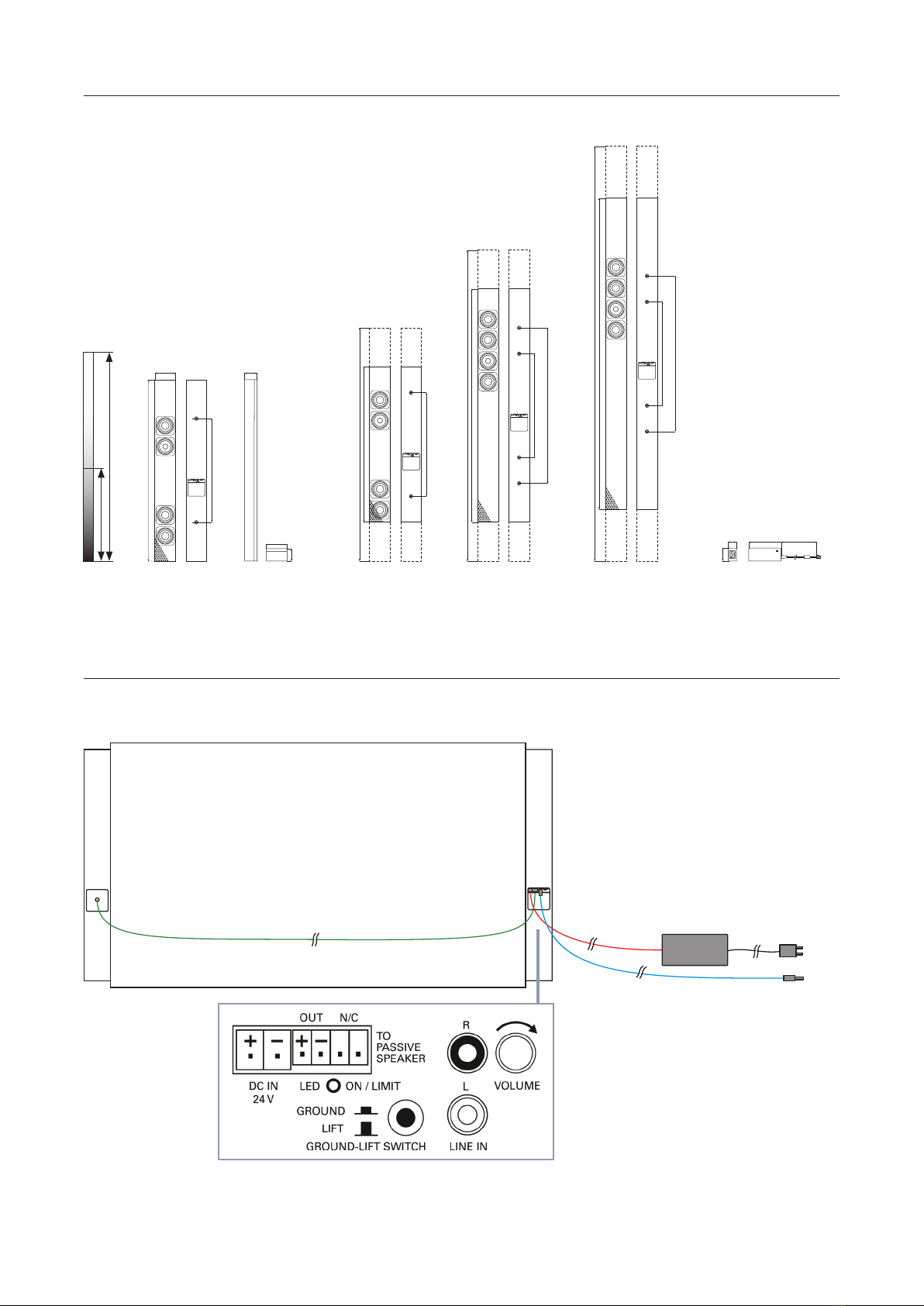
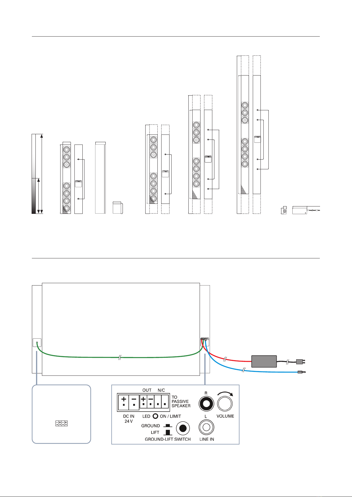
1. Connecting audio cables
Connect the line out or the headphone output of the display or other device to the line-in cinch
input on the active speaker’s connecting terminal. (If the display only has one digital audio output,
the signal must rst be converted.)
Connect the passive speaker (right) to the four-pole speaker terminal on the connecting terminal.
On model DL-A 2.0, the speaker cable is already attached to the passive speaker. On model
DL-A 2.2, connect the active and passive speakers to the four-pole speaker cable provided
(four-pole connectors on both sides).
2. Connecting the power supply
Turn the volume control for the active speaker all the way to the left (volume 0).
Insert the mains adapter provided into the green power supply terminal on the active speaker
and connect to the mains grid using the cold device cable.
3. Starting up the speaker system
Switch on the display or other device and set the output volume of the audio output to approximately 60-70 percent.
The speakers feature an automatic switch-on function and automatically activate when an audio signal is detected
at the input. When this happens, the LED in the terminal panel lights up green.
Turn the volume controller on the connecting terminal up to the desired operating volume.
4. Grounding the speakers (ground lift switch)
Depending on the grounding used for the display and other connected components (e.g. PC and crossover switches),
the speakers may or may not have to be grounded. The ground lift switch is designed to do this. If the other devices
are grounded, the speakers should not be grounded (ground lift). If the devices are not grounded, the speakers should
be grounded (ground). Incorrect grounding will result in buzzing sounds and interference.
5. Automatic switch-on function
If the speakers do not receive a signal for more than ten minutes, they automatically switch to standby.
The LED in the terminal panel goes out.
2. Connection with DL-A-/SB-A-Speaker Systems to Displays or Players
DL-A 2.0 Connecting Terminal
Anschluss Passiv-Lautsprecher
Connecting Terminal DL-A 2.0 DL-A 2.2 Connecting Terminal
SB-A 2.0 / SB-A 2.0 CAM(+) / SB-A 2.2 Connecting Terminal
Anschluss Passiv-Lautsprecher

6
Active stereo speaker pair with DSP
Very linear frequency range
Optimized speech intelligibility
2 × 50 watts power capacity
Automatic switch-on
• Switchable Ground-Lift
Customized versions with height on measure for
display heights from 600 up to 1600 mm
VESA mounts for display widths up to 2400 mm
Technical Data
Principle Active stereo speaker pair with
class-D ampli ers and DSP.
Left speaker with ampli er module,
right speaker passive.
Components 2 × 2.5“ full-range drivers + 2 × 2.5“
woofers + 4 × 2.5“ passive radiators
Frequency range 55 Hz – 20 kHz
Ampli er output 2 × 50 watts
Sensitivity max. 109 dB (1W/1m)
Nominal dispersion 120°
Connector Input cinch stereo, pluggable
Active speaker system terminals to connect passive
speaker and extern power supply,
input cable mini jack 3.5 mm to cinch,
1.5 m;
Connector Connecting cable with plug
Passive speaker
Input sensitivity -6 dBU for full modulation, input-
impedance 10 kohms
Operational controls Volume control, LED ON/Clip
Automatic switch-on Switches into an idle state (SLEEP)
automatically when the input signal
is absent for over 5 min.
Power supply Extern power supply 24 VDC, 40 VA
Mains connection 90 – 240 VAC
Dimensions (W × H × D) 80 × 700 × 48 mm (per speaker)
Weight 6 kg (pair)
Material Cabinet aluminium, front precision
steel grille, powder-coated, black
Fastening points Threaded inserts 2 × M 6 at rear
(per speaker)
Warranty 5 years
3. Displaylautsprecher
3.1. DL-A 2.0 Active Stereo Display Speaker Pair with integrated DSP
Key Features
Model Version
DL-A 2.0 Standard model
700 mm, RAL 9005
Customized versions Height on heasure
Display height
DL-A 2.0-900 600 – 900 mm
DL-A 2.0-1200 900 – 1200 mm
DL-A 2.0-1600 1200 – 1600 mm
Accessories
Mounts Display width
DL-VESA 1400 1150 – 1400 mm
DL-VESA 1650 1400 – 1650 mm
DL-VESA 1900 1650 – 1900 mm
DL-VESA 2150 1900 – 2150 mm
DL-VESA 2400 2150 – 2400 mm
Wall-mount
WH 80 Adjustable to a distance of 35
to 110 mm from the wall, pair
(2 pairs per speaker pair)
Pivotable wall-mount
SH 50 30 mm wall distance,
(2 pieces per speaker pair)
7
DL-A 2.0 Speaker Connection
Backside
Right speaker
passive
Left speaker
active
2-pole cable with connector
Stereo Input Cable
Jack 3.5 mm to Cinch, 1.5 m
Power Supply
24V DC 40 watts
CCE Power Cord
1.5 m
DC Cable Lenght
1 m
Back View
Dimensions
Speaker Connection
31,5
50
125 ca. 1000
Threaded inserts M 6
Lids top bottom/
Sides
Front Back
DL-A2.0 Standard
Customized version 9 1200 ... 00 mm
DL-A2.0-900
DL-A2.0-1200
DL-A2.0-1600
00 ... 00 mmCustomized version 6 9
Customized version 12 1600 ... 00 mm
PowerSupply
Connecting Terminal Active Speaker (left)
Individual Display Speakers from 600 mm up to 1600 mm height
8
Key Features
Modell Ausführung
DL-A 2.2 Standard model
700 mm, RAL 9005
Customized versions Height on measure
Display height
DL-A 2.2-900 700 – 900 mm
DL-A 2.2-1200 900 – 1200 mm
DL-A 2.2-1600 1200 – 1600 mm
Accessories
Mounts Display width
DL-VESA 1400 1150 – 1400 mm
DL-VESA 1650 1400 – 1650 mm
DL-VESA 1900 1650 – 1900 mm
DL-VESA 2150 1900 – 2150 mm
DL-VESA 2400 2150 – 2400 mm
Wall-mount
WH 80 Adjustable to a distance of 35
to 110 mm from the wall, pair
(2 pairs per speaker pair)
Pivotable wall-mount
SH 50 30 mm wall distance,
(2 pieces per speaker pair)
3.2. DL-A 2.2 Active Stereo Display Speaker Pair with DSP and integrated Subwoofers
Technical Data
Principle Active 2-way stereo speaker pair
with class-D ampli ers and DSP.
Left speaker with ampli er module,
right speaker passive.
Components 2 × 2.5“ full-range drivers + 6 × 2.5“
woofers + 12 × 2.5“ passive radiators
Frequency range 42 Hz – 20 kHz
Ampli er output 2 × 50 watts + 2 × 100 watts
Sensitivity max. 112 dB (1W/1m)
Nominal dispersion 120°
Connector Input cinch stereo, pluggable
Active speaker system terminals to connect passive
speaker and extern power supply,
input cable mini jack 3.5 mm to cinch,
1.5 m;
Connector Connecting cable with plug
Passive speaker
Input sensitivity -6 dBU for full modulation, input-
impedance 10 kohms
Operational controls Volume control, LED ON/Clip
Automatic switch-on
Switches into an idle state (SLEEP)
automatically when the input signal
is absent for over 5 min.
Power supply Extern power supply 24 VDC, 90 VA
Mains connection 90 – 240 VAC
Dimensions (W × H × D) 80 × 700 × 103 mm (per speaker)
Weight 9 kg (pair)
Material Cabinet aluminium, front precision
steel grille, powder-coated, black
Fastening points Threaded inserts 2 × M 6 at rear
(per speaker)
Warranty 5 years
Active 2-way stereo speaker pair with DSP
Very linear frequency range
Optimized speech intelligibility
Integrated subwoofer
2 × 50 + 2 × 100 watts power capacity
Automatic switch-on
Switchable Ground-Lift
Customized versions with height on measure
from 700 up to 1600 mm
VESA mounts for display widths up to 2400 mm
9
DL-A 2.2 Speaker Connection
Backside
Right speaker
passive
Left speaker
active
4-pole cable with connector
Stereo Input Cable
Jack 3.5 mm to Cinch, 1.5 m
Power Supply
24V DC 90 watts
CCE Power Cord
1.5 m
DC Cable Lenght
1 m
Back View
Dimensions
Speaker Connection
08
400
007
103
80
103
400
006
32
60
125 ca. 1000
400
Thread M 6ed inserts
Custom Height 700 ... 900 mm
Lids top/bottom
Sides
Front Back
DL-A2.2 Standard
Custom Height 900 ... 1200 mm
Custom Height 1200 ... 1600 mm
400
006
DL-A2.2-900
DL-A2.2-1200
DL-A2.2-1600
PowerSupply
Connecting Terminal Active Speaker (left)
Individual Display Speakers from 700 mm up to 1600 mm height
Connecting Terminal
Passive Speaker
LOW HIGH
INPUT

10
Principle Passive stereo speaker pair
Components 2 × 2.5“ full-range drivers + 2 × 2.5“
woofers + 4 × 2.5“ passive radiators
Frequency range 55 Hz – 20 kHz
Impedance 2 × 4 ohms
Power capacity 2 × 50 watts
Sensitivity max. 109 dB (1W/1m)
Nominal dispersion 120°
Connectors Pluggable system terminals
Dimensions (W × H × D) 80 × 700 × 48 mm (per speaker)
Weight 6 kg (pair)
Material Cabinet aluminium, front precision
steel grille, powder-coated, black
Fastening points Threaded inserts 2 × M 6 at rear
(per speaker)
Warranty 5 years
Passive stereo speaker pair
Very linear frequency range
Optimized speech intelligibility
2 × 50 watts power capacity
4 ohms impedance
Customized versions with height on measure
from 600 up to 1600 mm
VESA mounts for display widths up to 2400 mm
3.3. DL 2.0 Passive Stereo Display Speaker Pair
Technische Daten
Key Features
Model Version
DL 2.0 Standard model
700 mm, RAL 9005
Customized versions Height on measure
Display height
DL 2.0-900 700 – 900 mm
DL 2.0-1200 900 – 1200 mm
DL 2.0-1600 1200 – 1600 mm
Accessories
Mounts Display width
DL-VESA 1400 1150 – 1400 mm
DL-VESA 1650 1400 – 1650 mm
DL-VESA 1900 1650 – 1900 mm
DL-VESA 2150 1900 – 2150 mm
DL-VESA 2400 2150 – 2400 mm
Wall-mount
WH 80 Adjustable to a distance of 35
to 110 mm from the wall, pair
(2 pairs per speaker pair)
Pivotable wall-mount
SH 50 30 mm wall distance,
(2 pieces per speaker pair)
11
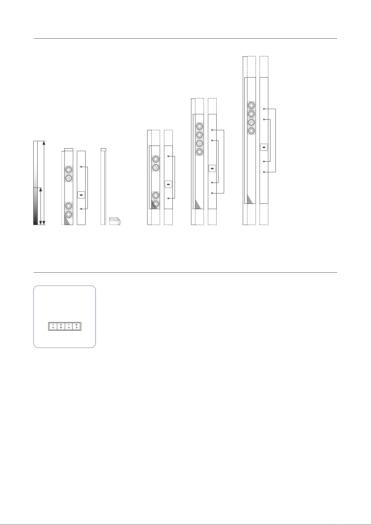
Dimensions
08
400
400
400
006
400
006
007
48
80
48
Threaded inserts M 6
Lids top/bottom
sides
Front Back
DL 2.0Standard
Customized Version 9 1200 ... 00 mm
DL 2.0-900
DL 2.0-1200
DL 2.0-1600
00 ... 00 mmCustomized Version 6 9
Customized Version 12 1600 ... 00 mm
Individual Display Speakers from 600 mm up to 1600 mm height
Speaker Connection
Connecting Terminal DL 2.0
INPUT THRU

12
The DL-VESA mounts are designed to x our display speakers
of DL series on displays with VESA-points at rear. The mounts
are adjustable for di erent display widths and heights.
Back view: display with xed display speakers on DL-VESA.
The mounts are suitable for all standard VESA-points.
DL-VESA Display-Fastening-Points
4. Mounts for Display Speakers
4.1. DL-VESA Technical Data
Models
DL-VESA 1400 1150 – 1400 mm
DL-VESA 1650 1400 – 1650 mm
DL-VESA 1900 1650 – 1900 mm
DL-VESA 2150 1900 – 2150 mm
DL-VESA 2400 2150 – 2400 mm
400
600
200
300
400
600
200
800
400
Threads M 6
Fastening-Points
VESA 200 ... 400
Fastening-Points VESA 200 ... 800

13
Dimensions
871
1121
1371
1621
1871
2121
600
300
200
400
30 18 15
40
DL-VESA 1150
DL-VESA 1400
DL-VESA 1650
DL-VESA 1900
DL-VESA 2150
DL-VESA 2400
30 18
30 18
30 18
30 18
30
18
L-bracket
220
40
45
45
190
30
T-bracket left
135
50
20
70
20
T-bracket right
135
50
20
70
20
Extension
40
50
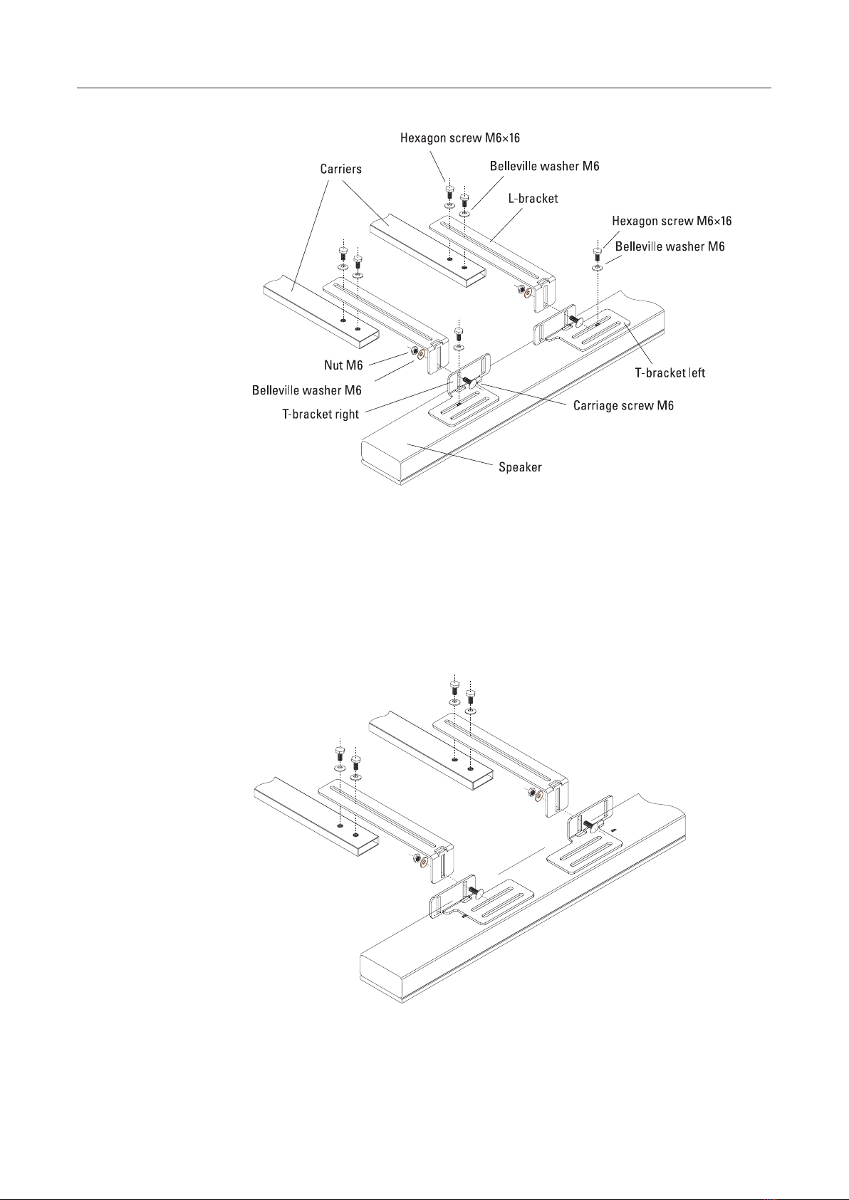
Parts of DL-VESA Mount
2 × Carrier 4 × L-bracket
12 × Hexagon
screw M 6 × 16
2 × T-bracket left
8 × Carriage screw
M 6 × 16
2 × T-bracket right
20 × Belleville
washer M 6
4 × Extension 8 × Nut M 6
The parts of the DL-VESA mounts can be used dierent, depending on dimensions of display and speaker model (see page 12 – 15)
14
Variante A
For 200 – 400 mm VESA
standard mounts.
Attach the T-shaped
brackets directly to the
L-shaped brackets;
position the T-brackets
symmetrically, with the
baseplates facing outwards.
The L-shaped brackets can
be attached forwards or
backwards depending on
the depth.
Variante B
For 400 – 600 mm VESA
standard mounts.
Attach the T-brackets
directly to the L-brackets;
position the T-brackets
symmetrically, with the
baseplates facing inwards.
4.2. DL-VESA Assembly with DL-A 2.0 / DL 2.0

15
Variante C
For asymmetrical VESA
standard mounts.
Attach the T-brackets
directly to the L-brackets;
use two identical
T-brackets on each side.
The L-brackets can be
mounted on the front or
back of the T-bracket
depending on the depth
of the display.
Variante D
For very deep displays.
Use extension plates
between the T-brackets
and the L-brackets to add
extra space.
4.2. DL-VESA Assembly with DL-A 2.0 / DL 2.0
16
Variante E
For VESA standard mounts
under 200 mm.
Attach the T-brackets
directly to the L-brackets;
position the T-brackets
symmetrically, with the
baseplates facing outwards.
Variante F
For a VESA standard
mounts over 600 mm.
Attach the T-brackets
directly to the L-brackets;
position the T-brackets
symmetrically with the
baseplates facing inwards.
4.2. DL-VESA Assembly with DL-A 2.0 / DL 2.0

17
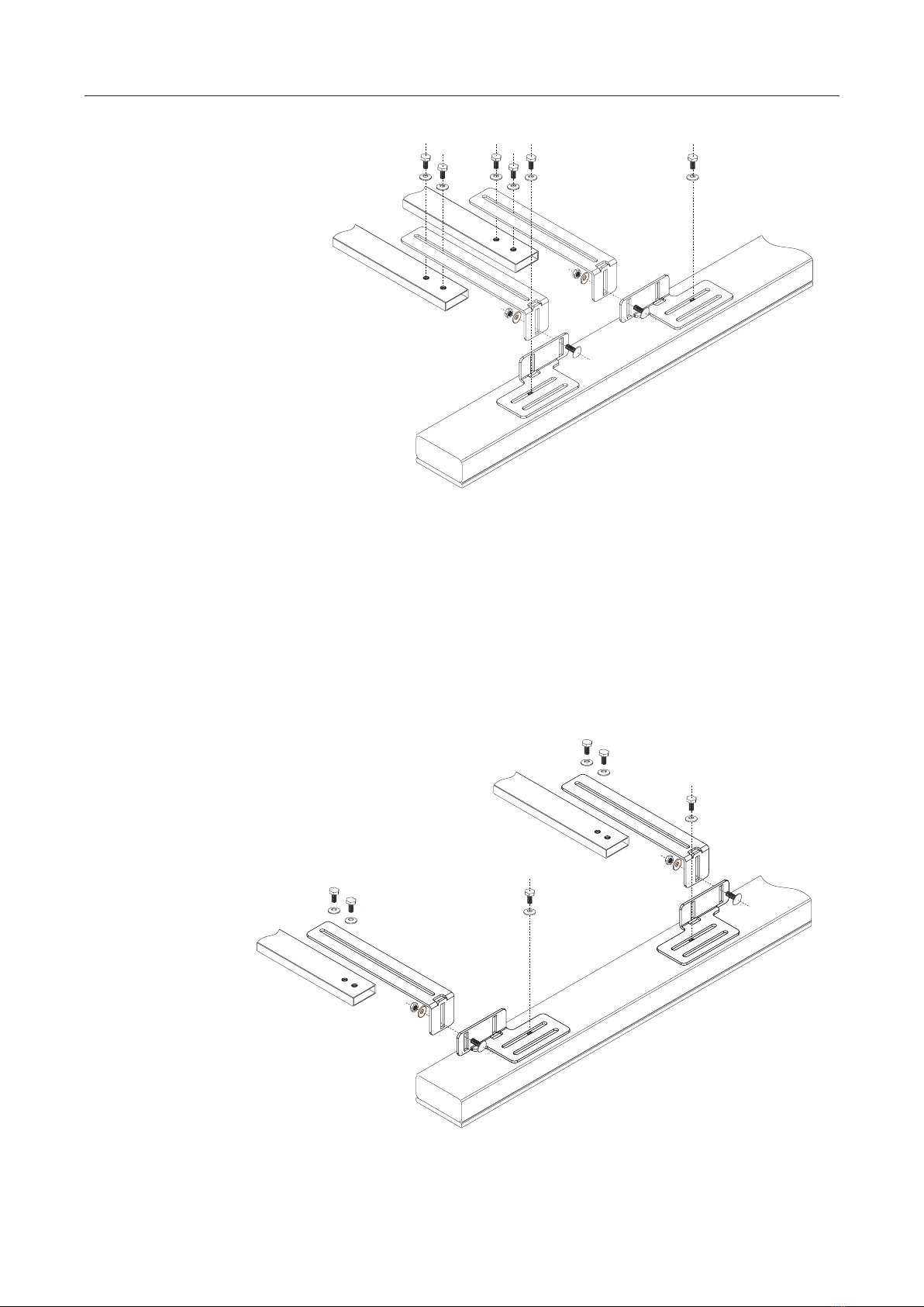
Extensions
Variante G
For flat displays used with
deep DL-A 2.2 display
speakers, the T-brackets
are mounted facing
forwards to compensate
for the gap.
Variante H
If you need extra length,
use extension plates
between the T-brackets
and the L-brackets.
4.3. DL-VESA Assembly with DL-A 2.2

18
The wall mount WH 80 is adjustable for a wall distance from 35 up to 110 mm (two pairs are needed per speaker-pair).
L-bracket A L-bracket A Wall-distance 35 – 110 mm
4.5. WH 80 Wall-Mount Assembly
31
40
50
40
34 72
35
110
L-Winkel A
L-Winkel B
Wandabstand von 35 – 110 mm
31
40
50
40
34 72
35
110
L-Winkel A
L-Winkel B
Wandabstand von 35 – 110 mm
31
40
50
40
34 72
35
110
L-Winkel A
L-Winkel B
Wandabstand von 35 – 110 mm
Dimensions
Fix the L-brackets A with the provided
screws at the rear of the speaker
(hexagon M 6 × 16 + belleville washers).
Fix the L-brackets B on the wall and
connect them with the L-brackets A
(hexagon M 6 × 10 + belleville washers).
The speakers can also be xed inclined.
4.4. WH 80 Wall-Mount Technical Data

19
The pivotable wall mount SH 50 has a wall distance of 33 mm and is pivotable up to 45°. (Two peaces are needed per speaker pair)
4.7. SH 50 Pivotable Wall-Mount Assembly
4.6. SH 50 Pivotable Wall-Mount Technical Data
Dimensions
16,3
74,5
74,5
33 10
400
466
40
33
536
L- Winkel
U-Bügel
16,3
74,5
74,5
33 10
400
466
40
33
536
L- Winkel
U-Bügel
Fix the U-bracket on the wall and connect
them with the L-brackets (hexagon screws
M 6 × 10 + belleville washers).
The speakers can also be swivelt up to
45° as required.
Fix the L-brackets with the provided screws
at the rear of the speaker (hexagon screws
M 6 × 16 + belleville washers).

20
Principle Active stereo soundbar with DSP
Components 2 × 2.5“ full-range drivers + 2 × 2.5“
woofers + 4 × 2.5“ passive radiators
Frequency range 55 Hz – 20 kHz
Ampli er output 2 × 50 watts
Sensitivity max. 109 dB (1 W/1m)
Nominal dispersion 120°
Connectors Input cinch stereo, pluggable system
terminals to connect extern power
supply, input cable mini jack 3.5 mm
to cinch, 1.5 m
Input sensitivity -6 dBU for full modulation, input-
impedance 10 kohms
Operational controls Volume control, LED On/Limit,
at back Ground-Lift-Switch
Automatic switch-on Switches into an idle state (SLEEP)
automatically if the input signal is
absent for over 5 min.
Power supply Extern power supply 24 VDC, 40 VA
Dimensions (W × H × D) 960 × 80 × 48 mm
Weight 5 kg
Material Cabinet aluminium, front precision
steel grille, powder-coated
Fastening points Threaded inserts 4 × M 6 at rear
Warranty 5 years
Active stereo soundbar with DSP
Very linear frequency range
Optimized speech intelligibility
2 × 50 watts power capacity
Automatic switch-on
Switchable Ground-Lift
Customized versions on measure for display widths
from 960 up to 2350 mm
VESA mounts for display heights up to 100 inches
5. Soundbars
5.1. SB-A 2.0 Active Stereo Soundbar with Integrated DSP
Technical Data
Key Features
Model Version
SB-A 2.0 Standard model
960 mm, RAL 9005
Customized versions Width on measure
Display width
SB-A 2.0-1200 960 – 1200 mm
SB-A 2.0-1600 1200 – 1600 mm
SB-A 2.0-2000 1600 – 2000 mm
SB-A 2.0-2350 2000 – 2350 mm
Accessories
Mount
SB-VESA VESA-mount for Displays
from 40“ – 100“
Wall-mount
WH 80 Adjustable to a distance of
35 to 110 mm from the wall, pair
(1 pair per soundbar)
This manual suits for next models
4
Table of contents
Other lb Speakers manuals


