JBL STUDIO L226C User manual

L226W, L226C, L228C,
LS326W, LS326C, LS328C
STUDIO
™
LSERIES
OWNER’S GUIDE
®
Studio L, O.M. 9/26/06 10:52 AM Page 1

For more than 60 years, JBL has been involved in every aspect of music and
film recording and reproduction, from live performances to the recordings you
play in your home, car or office.
We’re confident that the JBL speakers you have chosen will provide every note
of enjoyment that you expected – and that when you think about purchasing
additional audio equipment for your home, car or office, you will once again
choose JBL.
Please take a moment to register your product on our Web site at www.jbl.com.
It enables us to keep you
posted on our latest advance
ments, and helps us to
better understand our customers and build products that meet their needs and
expectations.
UNPACKING THE SPEAKERS
Carefully unpack the speakers. If you suspect damage from transit, report it
immediately to your dealer and/or delivery service. Keep the shipping carton
and packing materials for future use. All models include a mounting template
and paint shield.
PLANNING YOUR SYSTEM
Figure 3. This overhead view shows a 6- or 7-channel home theater system
arrangement. Left/right rear channels are for a 7-channel system. Center rear
channel is for a 6-channel system.
NOTE: Figures 1, 2 and 3 show recommended speaker locations. You may also
follow these general placement suggestions when installing the speakers in
the ceiling.
Couch
Left
Front
Channel
Left
Surround
Channel
Right
Surround
Channel
Right
Front
Channel
Center
Channel
Left
Rear
Channel
Right
Rear
Channel
Center
Rear
Channel
(above or below TV)
JBL Subwoofer
(optional)
Couch
Left
Front
Channel
Left
Surround
Channel
Right
Surround
Channel
Right
Front
Channel
Center
Channel
JBL Subwoofer
(optional)
Figure 2. This overhead view shows a typical home theater
system arrangement.
Couch
Left
Front
Channel
Right
Front
Channel
JBL Subwoofer
(optional)
Figure 1.
THANK YOU FOR CHOOSING JBL
2
Studio L, O.M. 9/26/06 10:52 AM Page 2

3
PLACEMENT
STEREO
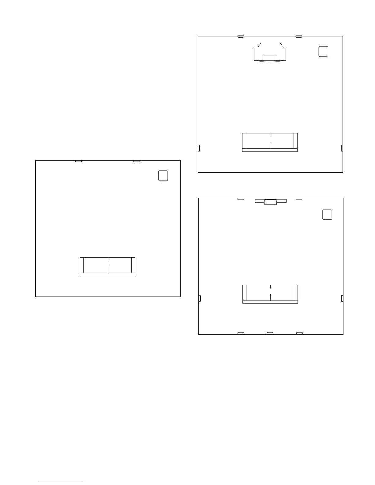
Before deciding where to place your speakers, survey your room and think
about placement, keeping the following points in mind, and using Figure 1,
on previous page, as a guide:
•For best results, place the speakers 6'–8' apart.
•When installing in the wall, position each speaker so that the tweeter is
as close to ear level as practical.
•Refer to “Home Theater” below if you also plan to use the speakers in
ahome theater system.
HOME THEATER
For front-channel use, place one speaker on the left and another on the
right along either side of the television.
Acenter channel speaker should go directly above or below the television
and can be an in-wall, in-ceiling or freestanding center channel.
For left and right surround channels, place one speaker on the left and
another on the right, to the side of or slightly behind the listening area.
In 6- or 7-channel configurations, place the rear channel(s) behind the
listening position, as shown in Figure 3.
NOTE: AJBL powered subwoofer will add impact and realism to both
music and film soundtracks. Contact your JBL dealer for recommendations
on subwoofer models for your application.
Proper placement of the speakers is an important step in obtaining the most
realistic soundstage possible. These recommendations are for the optimal
placement of the loudspeakers. Use these placement recommendations as
aguide. Slight variations will not diminish your listening pleasure.
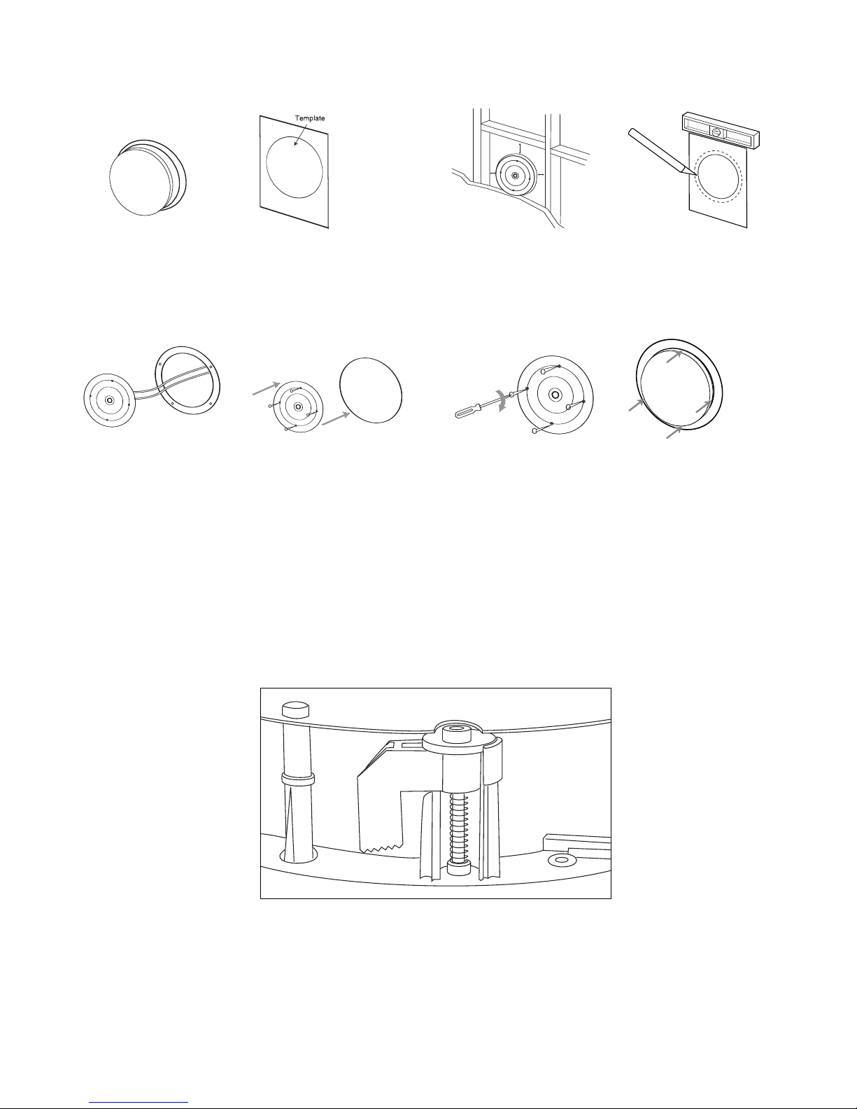
INSTALLATION
The Studio™LSeries in-wall and in-ceiling speakers were designed to be easily
installed. However, if you are unable to clearly and fully understand and follow
the instructions in this manual, or if you are unsure of your ability to properly
install these loudspeakers, please contact your dealer or a qualified installer.
TOOLS NEEDED
Phillips #2 screwdriver
(Do not use a powered screwdriver
of any kind)
Measuring tape Utility knife
Pencil
Carpenter’s level Awl
CONNECTION TIPS
SPEAKER CONNECTIONS
WireLength Recommended Size
Up to 100 ft. 16-gauge
Greater than 100 ft. 12-gauge
TURN OFF ALL POWER
Before completing the installation, you must connect your speakers to your
system. First, turn off all audio-system power. Use high-quality speaker wire
to make your connections. Use at least #16-gauge speaker wire with polarity
coding. Heavier gauge wire is recommended for larger distances. Consult the
chart above or your dealer for recommendations. The side of the wire with a
ridge or other coding is usually considered positive (+) polarity. Also, consult
the owner’s manuals that were included with your amplifier or receiver to
confirm connection procedures.
Observe polarities when making speaker connections, as shown in Figure 4.
Connect each + terminal on the back of the amplifier or receiver to the
respective + (red) terminal on each speaker. Connect the – (black) terminals
in the same way.
IMPORTANT!
Do not reverse polarities (i.e., + to – , or – to +) when making connections.
Doing so will cause poor imaging and diminished bass response. Be certain
that positive and negative wire strands are completely isolated to avoid short
circuits that may damage your equipment.
Figure 4.
Studio L, O.M. 9/26/06 10:52 AM Page 3

4
EXISTING CONSTRUCTION
L226C, L228C, LS326C, LS328C
1. Remove the plastic paint
shield from the speaker frame. 2. Determine the correct
speaker location.
NOTE: Use the included
template when cutting the
drywall.
≥1/2"
≥1/2"
≥1/2"
3.
NOTE: Always allow at
least a 1/2 inch between a
wall stud and the speaker
cutout or the locking tabs
will not be able to swivel
into place.
4. Ensure that the drywall or plywood
board or other appropriate wallboard
is at least 1/2-inch thick and confirm
that the board material is capable of
withstanding the weight of the speaker
you will be installing. Cut the drywall.
5. Connect the speaker
wires to the speaker. 6. Make sure all four locking tabs
are properly positioned against
the locking tab stops that are
located on the speaker frame (see
Figure 5 below). After confirming
this, carefully place the frame
assembly in the wall and confirm
that there is no more than 1/8-inch
play between the frame and the
wall cutout. After positioning the
speaker in the mounting location,
back each screw out one full turn
(turn counterclockwise).
7. Screw down each of the four
Phillips-head screws, alternating
between the four screws. The
locking tabs will swivel into place
and secure the unit to the rear
surface of the wall panel. Hand-
tighten with a nonpowered,
straight-handle regular screw-
driver only. Do not use a socket
wrench, a powered screwdriver,
adrill or any other powered tool.
Confirm that the speaker is firmly
and securely held in place and
that all four locking tabs are firmly
resting against the wall panel.
8. Attach the metal grille
and logo, if desired.
Figure 5.
Studio L, O.M. 9/26/06 10:52 AM Page 4

5
7. Screw down each of the four
Phillips-head screws, alternating
between the four screws. The
locking tabs will swivel into place
and secure the unit to the rear
surface of the wall panel. Hand-
tighten with a nonpowered,
straight-handle regular screw-
driver only. Do not use a socket
wrench, a powered screwdriver,
adrill or any other powered tool.
Confirm that the speaker is firmly
and securely held in place and
that all four locking tabs are firmly
resting against the wall panel.
L226W, LS326W
1. Remove the plastic paint
shield from the speaker
frame.
2. Determine the correct
speaker location.
NOTE: Use the included
template when cutting the
drywall.
3. NOTE: Always allow
at least a 1/2 inch between
awall stud and the speaker
cutout or the locking tabs
will not be able to swivel
into place.
≥1/2"
≥1/2"
≥1/2"
4. Ensure that the drywall or plywood
board or other appropriate wallboard
is at least 1/2-inch thick and confirm
that the board material is capable of
withstanding the weight of the speaker
you will be installing. Cut the drywall.
5. Connect the speaker
wires to the speaker.
6. Make sure all four locking tabs
are properly positioned against
the locking tab stops that are
located on the speaker frame (see
Figure 6 below). After confirming
this, carefully place the frame
assembly in the wall and confirm
that there is no more than 1/8-inch
play between the frame and the
wall cutout. After positioning the
speaker in the mounting location,
back each screw out one full turn
(turn counterclockwise).
8. Attach the metal grille
and logo, if desired.
Figure 6.
Studio L, O.M. 9/26/06 10:52 AM Page 5

6
NEW CONSTRUCTION
PAINTING THE SPEAKER
FRAME AND GRILLE
Studio L in-wall and in-ceiling loudspeakers can be painted to match any
décor. If you wish to change their color, the satin finish on the grille and frame
will function as a primer coat. Before painting, install the paint shield (inner
section of template in the assembly kit) securely into the recess in the baffle.
This will protect the speaker components and baffle from paint residue. Use a
high-quality spray paint, and apply a thin coat of color. Be certain the grille
perforations remain free of paint. Filling them with paint will diminish the
sound quality.
NOTE: Gently remove the acoustical foam blanket from the grille before paint-
ing. Reattach the blanket after the paint has dried.
If you wish to preinstall a rough-in frame before the drywall is installed, you
will need to purchase the correct rough-in-frame kit for your model:
Speaker Model Rough-In-Frame Kit
L226W, LS326W RIF 6
L226C, LS326C RIF 6CS
L228C, LS328C RIF 8C
Detailed installation instructions are supplied with the rough-in kit.
OPERATION
SURROUND MODES
When using the system in a Dolby®Digital or DTS®home theater system,
make sure all speakers are set to “Small.”When using the Studio L in-wall
and in-ceiling speakers in a Dolby Pro Logic®home theater system, make sure
the receiver’s center channel mode is set to “Normal.”
Some Dolby Digital-equipped receivers/processors offer different setup
options for each source or surround mode: e.g., CD-stereo, videotape, Dolby
or Pro Logic. In each case, follow your equipment’sinstructions to ensure that
the subwoofer (if you have one) output is turned on and that the speakers are
set to “Small” in each mode.
Studio L, O.M. 9/26/06 10:52 AM Page 6

SPECIFICATIONS
Studio L L226W L226C L228C
Frequency Range (–6dB) 30Hz – 20kHz 30Hz – 20kHz 28Hz – 20kHz
Recommended 10 – 125 Watts 10 – 125 Watts 10 – 135 Watts
Amplifier Power Range
Sensitivity 89dB 89dB 90dB
(2.83V @1meter)
Nominal Impedance 8Ohms 8 Ohms 8 Ohms
Crossover Frequency 3,000Hz; 2,500Hz; 2,500Hz;
24dB/Octave 18dB/Octave 18dB/Octave
Low-Frequency Driver 6-1/2" (165mm) 6-1/2" (165mm) 8" (200mm)
Aluminum cone Aluminum cone Aluminum cone
High-Frequency Driver 1" (25mm) 1" (25mm) 1" (25mm)
Titanium-laminate Titanium-laminate Titanium-laminate
External Dimensions 8-1/2" x 11" Diameter: 9-3/16" Diameter: 10-7/8"
(W x H) (216mm x 280mm) (233mm) (276mm)
Mounting Cutout Size 7" x 9-1/2" Diameter: 7-7/8" Diameter: 9-1/2"
(W x H) (178mm x 241mm) (200mm) (241mm)
Mounting Depth 3-9/16" (90mm) 4-1/8" (104mm) 4-5/8" (117mm)
Weight (Net) 3.5 lb (1.6kg) 3.5 lb (1.6kg) 5.8 lb (2.6kg)
Studio L LS326W LS326C LS328C
Frequency Range (–6dB) 30Hz – 30kHz 30Hz – 30kHz 28Hz – 30kHz
Recommended 10 – 135 Watts 10 – 135 Watts 10 – 150 Watts
Amplifier Power Range
Sensitivity 89dB 89dB 90dB
(2.83V @1meter)
Nominal Impedance 8Ohms 8 Ohms/channel 8 Ohms
Crossover Frequency 3,000Hz; 2,500Hz; 2,500Hz;
24dB/Octave 18dB/Octave 18dB/Octave
Low-Frequency Driver 6-1/2" (165mm) 6-1/2" (165mm) 8" (200mm)
Aluminum cone Aluminum cone Aluminum cone
High-Frequency Driver 1" (25mm) 1" (25mm) 1" (25mm)
Titanium Titanium Titanium
External Dimensions 8-1/2" x 11" Diameter: 9-3/16" Diameter: 10-7/8"
(W x H) (216mm x 280mm) (233mm) (276mm)
Mounting Cutout Size 7" x 9-1/2" Diameter: 7-7/8" Diameter: 9-1/2"
(W x H) (178mm x 241mm) (200mm) (241mm)
Mounting Depth 3-9/16" (90mm) 4-1/8" (104mm) 4-5/8" (117mm)
Weight (Net) 3.5 lb (1.6kg) 3.5 lb (1.6kg) 5.8 lb (2.6kg)
All features and specifications are subject to change without notice.
7
Studio L, O.M. 9/26/06 10:52 AM Page 7

JBL is a trademark of Harman International Industries, Incorporated, registered in the United States
and/or other countries. Pro Sound Comes Home and Studio Series are trademarks of Harman
International Industries, Incorporated.
Dolby and Pro Logic are registered trademarks of Dolby Laboratories.
DTS is a registered trademark of DTS, Inc.
®
PRO SOUND COMES HOME
™
Harman Consumer Group, Inc., 250 Crossways Park Drive, Woodbury, NY 11797 USA
8500 Balboa Boulevard, Northridge, CA 91329 USA
516.255.4JBL (4525) (USA only) www.jbl.com
© 2006 Harman International Industries, Incorporated. All rights reserved.
Part No.
406-000-05529-E
Declaration of Conformity
We,Harman Consumer Group International
2, route de Tours
72500 Château du Loir
France
declare in own responsibility that the products described in this
owner’s manual are in compliance with technical standards:
EN 61000-6-3:2001
EN 61000-6-1:2001 Laurent Rault
Harman Consumer Group International
Château du Loir, France 9/06
Studio L, O.M. 9/26/06 10:52 AM Page 8
This manual suits for next models
5
Table of contents
Other JBL Speakers manuals

JBL
JBL Grand Touring Series GTO18T User manual

JBL
JBL L220 User manual

JBL
JBL VS3215-9 User manual

JBL
JBL Cinema SB350 User manual

JBL
JBL VT4880A User manual

JBL
JBL Intellivox ADC V90 Mark II User manual

JBL
JBL ES10BK User manual

JBL
JBL Northridge Series E 100 User manual

JBL
JBL PRX312MD User manual

JBL
JBL 250Ti Jubilee User manual

JBL
JBL Studio S36IIPM User manual

JBL
JBL Link 10 User manual

JBL
JBL SoundPoint SP8C Series User manual

JBL
JBL SP6CSII SoundPoint Assembly instructions

JBL
JBL VTX Series User manual

JBL
JBL LOFT50 User manual

JBL
JBL 4671 User manual

JBL
JBL Control CRV User manual

JBL
JBL DPS-12 Use and care manual

JBL
JBL Charge 4 User manual