LBS Freedom Power Pack LBS-1250-FPP-STD User manual

Battery User Guide
Freedom Power Pack (FPP)
12V Portable Battery
-Camping
-Caravanning
-4WD
-Fishing
-Emergency Power
LBS-1250-FPP-STD
LBS-1250-FPP-DCC
POWERING FREEDOM

___________________________________________________________________________
Page 1 User Guide LBS-1250-FPP_1.32
Battery User Guide
V1.2 April 2018
Freedom Power Pack (FPP) – Portable Battery
LBS-1250-FPP-STD & DCC
12V | 50Ah | Portable Enclosure | STD & DCC version
This User Guide describes how to connect and operate the LBS-1250-FPP-STD and LBS-1250-
FPP-DCC versions of the FPP. As with all batteries, you should consider the mechanical and
environmental conditions that you intend to operate the battery in to maximise overall
performance and achieve the longest battery life. LBS offer these general guidelines;
however, you should seek LBS advice or that of a qualified electrical tradesperson if you are
in doubt.
LBS-1250-FPP-DCC version with
internal DC-DC charger and VSR

___________________________________________________________________________
Page 2 User Guide LBS-1250-FPP_1.32
Battery User Guide
V1.2 April 2018
Do’s and Don’ts – General Battery Safety & Performance
1. Ensure the battery is physically secure
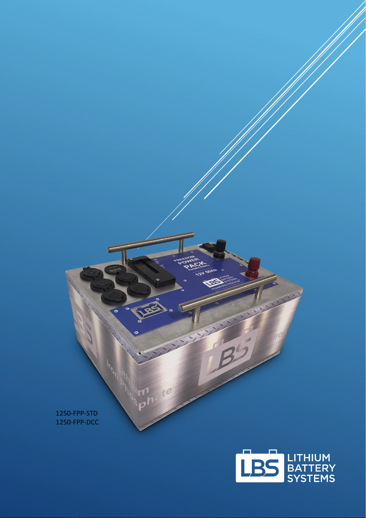
Even though the FPP is only 10kg and designed to be portable, it can still become a
dangerous projectile in a moving vehicle if not secured. Ensure the battery is safely
secured before travel.
2. Ensure the battery is operating within an acceptable temperature range
Like all batteries, LBS batteries operate and perform the best as well as last the longest
in a cool and stable temperature environment of between 10oC and 25oC. The
maximum window of acceptable operation is 0-45oC. If you regularly operate outside
of this suggested range you should change the battery location or actively cool or heat
the environment. If the ambient temperature that the battery operates in is >60oC you
should cease use immediately. Operating outside of these guidelines diminishes the
life and performance of the battery.
3. Ensure the battery is not exposed to repeated shock and vibration
Whilst the battery is robustly constructed it is not designed to operate continuously
in high shock or high vibration environments.
4. Ensure the battery is not exposed to water or high humidity
Whilst the battery is mechanically protected, the enclosure is not designed for a wet
or high humidity environment.
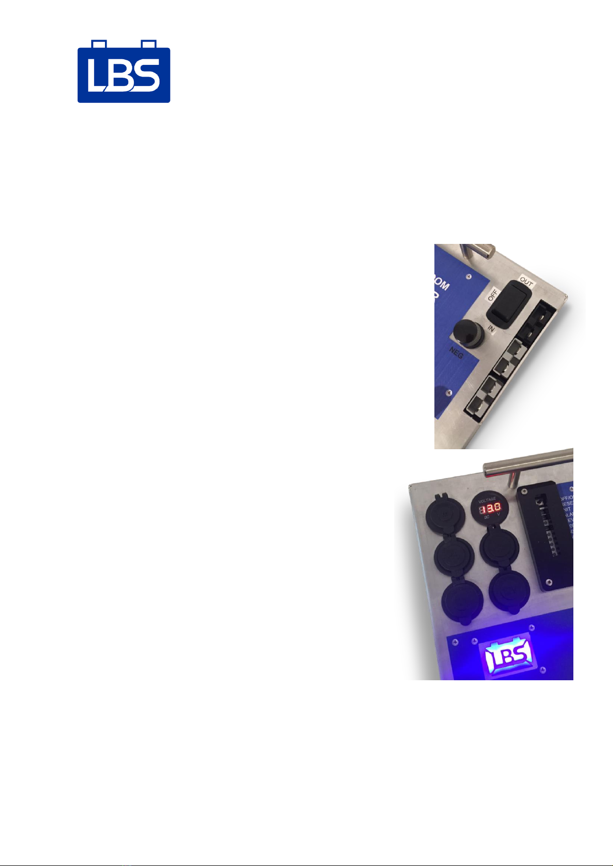
5. Ensure you do not short circuit the battery
Whilst the BMS will protect the internal cells it is highly recommended to avoid short
circuiting the battery. Pay attention when using metallic tools in the vicinity of the
terminals as accidentally contacting the positive and negative terminal with a metallic
object like a spanner will cause a short circuit and sparks. Always keep the plastic caps
screwed on when not using the terminals.
Be careful not to short the terminals, use the plastic caps when not in use

___________________________________________________________________________
Page 3 User Guide LBS-1250-FPP_1.32
Battery User Guide
V1.2 April 2018
Always perform work on passive wiring with the battery in the OFF position. If you are
unsure how to install your battery seek advice from LBS or a suitably qualified 12V
electrical tradesperson.
6. Charging and discharging at the same time
There are no issues with charging the battery and discharging the battery (running
loads) at the same time. The BMS counts the amps in and amps out and records the
level (state of charge).

___________________________________________________________________________
Page 4 User Guide LBS-1250-FPP_1.32
Battery User Guide
V1.2 April 2018
1.0 Battery Components
The battery has a number of components that the User should be familiar with:
1. Battery Terminals - Positive (Red) and Negative (Black)
2. Anderson Connectors - Grey, Black (DCC version)
3. DC Charger
4. Dual USB Ports x2
5. Cigarette Sockets x2
6. Merit Plug Socket
7. Voltmeter
8. State of Charge (SOC) level 20/40/60/80/100%
9. On/Off, Init, Reset Buttons and Alarm
1.1 Battery Terminals
The battery terminals are rated to the maximum capacity of the battery which is 100A for
both the STD and DCC versions of the FPP (High Power 200A version available on request).
The terminals can be used for either charge or load connections.
1.2 Anderson Connectors
The two grey Anderson connectors are rated to a maximum of 50A continuous operation for
either charge or load connections. The single black Anderson connector is the DC charger
(DCC version only).
3.DC Charger
9. On/Off, Init, Reset, Alarm
1. Terminals
2. Anderson
Connectors
4. USB Ports
7. Voltmeter
8. SOC 0-100%
5. Ciga Sockets
6. Merit Plug

___________________________________________________________________________
Page 5 User Guide LBS-1250-FPP_1.32
Battery User Guide
V1.2 April 2018
Grey General-purpose input or output (50A max)
Black DC charger (input 5-30V, 10A)
The User will need to consider the correct size of cable to connect to the Anderson plugs. LBS
has an extensive range of cables that are designed to operate safely at the rated current and
distance you would need. Contact LBS if you are not sure.
1.3 Internal DC Charger
The DCC version of the FPP comes with an internal DC charger (black
Anderson connector) and voltage sensing relay (VSR) function.
The black DC Charger switch activates the DC charger and has 3
positions –OUT, IN and OFF. Select the IN position when charging from
an external DC source such as the vehicle battery/alternator. Select the
OUT position when using the battery to charge an external battery
such as your vehicle starter battery. Select the OFF position when not
using the DC charger.
1.4 USB Ports
The FPP comes with two sets of dual USB ports, 5V 1A and
2.1A. These ports are outputs used for charging any device
which uses a USB connection for charging. Selecting the 2.1A
USB port will charge faster than the 1.0A port.
1.5 Cigarette Sockets
The FPP comes with two 12V cigarette sockets. These are
outputs used for powering portable fridge/freezers or any
other devices using cigarette plugs.
1.6 Merit Plug
The FPP comes with a merit socket as an alternative to the
cigarette sockets. Merit sockets are high quality heavy duty
connections that are ideal for high current draw
accessories. Merit plugs are smaller than both Ciga and Engel
sockets and are becoming the new standard in automotive
power connectors.
1.7 Voltmeter
The FPP comes with a voltmeter to indicate the battery voltage.

___________________________________________________________________________
Page 6 User Guide LBS-1250-FPP_1.32
Battery User Guide
V1.2 April 2018
1.8 Level / State of Charge (SOC)
To indicate the battery Level (aka State of Charge), use a pen or a key to
depress the Level button. There are 5 LEDs representing level in
increments of 20%:
1) 0-20% (flashing if very low)
2) 20-40%
3) 40-60%
4) 60-80%
5) 80-100%
The LED’s will turn off after 5 seconds to minimise internal power
consumption.
1.9 On/Off, Init and Reset Buttons
On/Off
To turn the battery on slide the switch to the right.
To turn the battery off slide the switch to the left.
Reset Button
The Reset button can be used to clear a fault, such as after the battery
has discharged to empty and disconnected the loads to protect itself.
Initialise Button
The Init button is to initialize the battery for the first time during
assembly, or if the battery has discharged below empty level and shut itself down completely.
This would only happen if the battery is left empty for a long time.
Alarm LED
The Alarm LED flashes when an issue occurs; the number of flashes in sequence indicate what
the issue is as below. There is also an audible buzzer.
1
Permanent Fault
2
Cell Under Voltage (battery empty)
3
BMS (MOSFETs) too hot
4
Battery too cold
5
Battery too hot
6
Short Circuit (Current > 1000A for 70µs)
RESET
LEDs
OFF-ON
INIT
ALARM
LEVEL
RESET
LEDs

___________________________________________________________________________
Page 7 User Guide LBS-1250-FPP_1.32
Battery User Guide
V1.2 April 2018
7
Over Load (Current > 500A for 1 second)
8
Over Current (Current > 100A for 10 seconds)
9
Communications lost between Atmel and TI BQ microcontrollers (both
on BMS).

___________________________________________________________________________
Page 8 User Guide LBS-1250-FPP_1.32
Battery User Guide
V1.2 April 2018
2.0 BMS (Battery Management System)
The Battery Management System is the brains of the battery and ensures the battery is safe
and has a long life of trouble-free operation. The BMS provides the following functions:
•Protects the battery from over-charge, over discharge, dead shorts or excessive loads.
•Balances the individual cells during charging.
During normal operation simply turn the battery ON knowing that the BMS is sitting in the
background keeping the battery safe and sound.
The BMS has:
•Master OFF/ON switch
•Reset button
•Initialization (Init) button
•Status light
•Level/ State of Charge (SOC) button
•5 LED’s to show Level / SOC (20/40/60/80/100%)
For normal operation slide the OFF/ON switch to the right and the SOC/Level LEDs will light
up for 5 seconds. By depressing the Level button, the battery will again
light the LED’s to indicate how full (SOC) the battery is.
The battery has an illuminated blue LBS logo which will glow when the
battery is ON.
2.1 FAQ
What do I do if the battery does not seem to be operating?
Turn the battery OFF and back ON by sliding the OFF/ON switch. If the blue logo is backlit you
should be up and running again. By depressing the Level (SOC) button you can check how full
the battery is as a State of Charge %. You will get 1-5 LED’s to show:
1) 0-20% (flashing if very low)
2) 20-40%
3) 40-60%
4) 60-80%
5) 80-100%
What do I do if the battery Status LED displays a red light?
Press the Reset button. If this does not work then turn the battery OFF and back ON as above.
If this fails, press the Init button.
3.0 Charging
The FPP can be charge from solar panels, from a vehicle or from the AC mains.

___________________________________________________________________________
Page 9 User Guide LBS-1250-FPP_1.32
Battery User Guide
V1.2 April 2018
3.1 Solar Panels
The FPP can be charged with a 12V solar panel such as a folding solar panel, solar blanket or
flexible solar panel. The battery can be charged with either regulated or unregulated solar,
via the following connections:
1) Either of the grey Anderson plugs, or
2) Battery terminals using alligator clips or ring terminals.
Unregulated solar (raw solar panel output) uses the BMS to function as a PWM solar
controller. Used in this way, the BMS will disconnect the solar panel from the battery when
the battery becomes full. However, care should be taken because the Voc (open circuit
voltage) of the solar panel may then be present at the loads, which may provide up to 20V or
more in sunlight (for a 12V solar panel) to any connected loads.
It is recommended to use regulated solar (a solar panel with its own solar charge controller)
which can be connected as shown below:
3.2 DC Source
The FPP can be charged from a DC source such as a vehicle alternator / start battery via the
black Anderson connector, by flicking the black DC Charger switch to IN (meaning DC input).
The DC charger contains a Voltage Sensing Relay (VSR) function that turns off charging if the
input voltage goes below 12.8V and only turns on charging again once the input voltage goes
above 13.3V. This is designed to prevent drawing power from the vehicle start battery when
the engine is not running (which would deplete the vehicle start battery). These voltage
setpoints are adjustable and can be tuned to suit factors such as cable size and length.

___________________________________________________________________________
Page 10 User Guide LBS-1250-FPP_1.32
Battery User Guide
V1.2 April 2018
The vehicles cigarette socket output can also be used as a DC charging source, as this is
ultimately connected to the battery / alternator of the vehicle. The VSR only lets the battery
charge when the engine is running.
3.3 Charging with an AC source
The FPP can be charged by an AC battery charger via the terminals using alligator clips or one
of the grey Anderson plugs.
3.4 Reverse Charging through the DC Charger
The Black DC Charger switch next to the black Anderson plug has the ability to reverse the
direction of DC charging, so that power goes FROM the FPP into the vehicle start battery to
charge it up, perhaps even via the cigarette socket of the vehicle. This is useful if your vehicle
(or your neighbour’s vehicle) is struggling to start the engine because of a flat battery.

___________________________________________________________________________
Page 11 User Guide LBS-1250-FPP_1.32
Battery User Guide
V1.2 April 2018
4.0 Running Loads
4.1 DC Loads
DC loads can be connected to the battery via the
1) USB ports
2) Cigarette sockets
3) Merit plug socket
4) Grey Anderson plugs
5) Battery Terminals
4.2 Jump Starting
The FPP can be used to jump start a vehicle, by connecting a cable with alligator clips to the
ring terminals or grey Anderson plug of the FPP. Be sure to only connect this for the few
seconds required to crank the engine; otherwise you may charge your starter battery too fast
and overheat it. Also, be careful not to short the connections on either end together when
connecting and disconnecting, as both ends will be live.
4.2 AC Loads
If a DC to AC inverter is connected to the battery then
AC loads can be powered. An inverter of up to 600W
can be connected via the grey Anderson plug. An
inverter of up to 1200W can be connected to the
battery terminals. Small inverters with a cigarette plug
can be connected via either of the two cigarette
sockets on the battery. If you want to use an inverter
of more than 1200W you will need the High Power (HP)
version of the FPP.
Before connecting an inverter please follow these
steps:
1) Turn the battery AND the inverter OFF
2) Connect the inverter cables
3) Turn the battery ON and wait 4 seconds
4) Turn the inverter ON.

___________________________________________________________________________
Page 12 User Guide LBS-1250-FPP_1.32
Battery User Guide
V1.2 April 2018
Battery Nameplates Specifications –DCC & STD

___________________________________________________________________________
Page 13 User Guide LBS-1250-FPP_1.32
Battery User Guide
V1.2 April 2018
CONTACTS
Lithium Battery Systems
Brisbane, Australia
National Sales Manager
Chris Carrigan
M: 040 404 1189
E: chris@lithiumbatterysystems.com.au
ABN 166 085 905 03
POWERING FREEDOM
This manual suits for next models
1
Table of contents
Other LBS Batteries Pack manuals