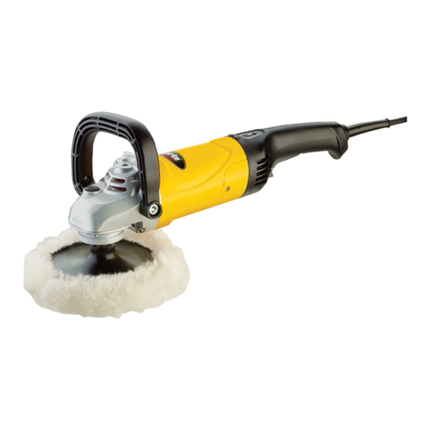
LC Power Tools UDOS 51E User manual

MODEL 51E
OPERATOR’S MANUAL
TO REDUCE RISK OF INJURY, OPERATOR MUST THROUGHLY READ,
UNDERSTAND AND FOLLOWING THIS OPERATOR’S MANUAL
Patented Worldwide
WITH STALL-AWARE®

-2-
UDOS 51E –Operator’s Manual v1.6
Prior to using, read, understand
and follow all safety warnings,
cautions, instructions, and specifications provided with
this power tool. Failure to follow all of the instructions
provided with this power tool may result in significant
property damage, personal injury, or death.
Do not operate the tool in the
presence of flammable vapors,
gases, liquids or dust. Powered tools may create sparks
at any time the tool plugged into a power source,
potentially resulting in an explosion.
Work in a neat, clean and well-lit area. Clutter and dimly
lit areas can result in accidents.
Keep bystanders away during operation. Proper personal
protective equipment must be worn by the tool operator
and any bystanders.
This tool must be plugged into
an outlet that exactly matches
the plug provided with the tool. NEVER MODIFY THE
POWER PLUG. Confirm the outlet and circuit providing
power to the tool is of sufficient capacity.
Do NOT expose or operate the tool in wet conditions.
Water entering the tool, or standing in or near water
while the tool is plugged in, greatly increases the risk of
electric shock.
Do NOT abuse the power cord. Never carry, swing, or
drag the tool by the power cord. DO NOT unplug the tool
by pulling on the power cord.
Inspect the power cord for any damage or degradation
such as cracks, splits, and swelling prior to use. Using the
tool with a damaged or degraded cord increases the risk
of electric shock.
The use of Ground Fault Circuit Interrupter (GFCI)
protected power source is recommended. A GFCI circuit
reduces the risk of electric shock.
Do NOT use this tool if you are
tired, or under the influence of
drugs, medications, or alcohol. Operating the tool while
impaired can result in serious personal injury or death.
Use Personal Protective Equipment (PPE). Always wear
ANSI Z87.1 protective eyewear and hearing protection
when using the tool. Additional PPE such as non-skid
safety shoes, vibration reduction gloves, particulate mask,
respirator, and a hardhat used when conditions indicate,
can greatly reduce the risk of personal injury.
Never carry the tool with you finger on or near the
trigger. Unintentional starting of the tool can result in
personal injury. Always confirm the trigger is in the off
(non-locked) position when plugging the tool into a power
source.
Dress properly. Do NOT wear loose fitting clothing, or
jewelry while operating the tool. Tie back long hair.
Loose clothing, jewelry, and hair can very quickly become
caught in the moving parts of the tool.
Do NOT overreach with the tool. Never operate the tool
with one hand. Always maintain proper control of the
tool by using both hands. Losing control of the tool can
result in serious personal injury.
Do NOT overload the tool. Select the proper size tool and
accessories for the job. Failure to do so can damage the
tool and result in an unsafe work condition.
Inspect the tool before use. Ensure the power switch
operates correctly, the power cord is in good condition,
and the mode adjustment mechanism is operating
smoothly.
Use only specified accessories. The use of unspecified
accessories may compromise performance, possibly
result in an unsafe work condition, and will void the
warranty.
This power tool is a combination Dual Action and Rotary
Polisher/Sander. It is intended for use in finish
correction of painted and gel-coated surfaces. Failure to
adhere to the following instructions may result in
significant property damage, serious personal injury, or
death. Operations such as sawing,
grinding, wire brushing, or
cutting-off are not authorized. Performing operations for
which a tool is not designed may result in an unsafe work
condition.
Use only accessories recommended for this power tool.
Use of non-authorized accessories will result in
substandard performance and may lead to an unsafe
work condition. Wear personal protective
equipment. Depending on the
application, use a face shield, with safety goggles or safety
glasses. As appropriate, wear dust mask, hearing
protectors, gloves and workshop apron capable of
stopping small abrasive or workpiece fragments. The eye
protection must be capable of stopping flying debris
generated by various operations. The dust mask or
respirator must be capable of filtrating particles
generated by your operation. Prolonged exposure to high
intensity noise may cause hearing loss.
Inspect tool and accessories
before use. The use of damaged,
cracked, or otherwise compromised accessories can
result in breakage and thrown hi-speed fragments. After
inspecting and installing an accessory, in an area free of
bystanders, with rotating plane of the tool pointed away,
run the tool at its maximum speed for one minute to
confirm proper operation. If any thrown fragments, or
excessive imbalance is encountered, immediately stop
the tool and inspect the tool and accessories thoroughly.
GENERAL SAFETY WARNINGS
MAINTAIN A SAFE WORK AREA
ELECTRICAL SAFETY
OPERATOR SAFETY
USE AND CARE
OPERATIONAL SAFETY
OPERATIONAL SAFETY

-3-
UDOS 51E –Operator’s Manual v1.6
Do NOT cover the cooling vents
with your hand during
operation. Obstructed vents can lead to motor
overheating, resulting a thermal shutdown and potential
tool damage. Beware of tool kickback.
Kickback is a result of misuse and
can occur when tool rotation is suddenly stopped by an
obstruction. A strong opposite direction reaction torque
is then transmitted through the tool body to the operator.
This can cause serious personal injury. To avoid kickback
avoid using the tool in areas where the rotating
accessories can become caught or pinched, such as
around mirrors, antennas, panel gaps and sharp contours.
The secure use of both hands on the tool in the designed
positions will minimized the risk of personal injury if
kickback occurs. Never use one hand to operate the tool.
Do not allow any loose portion
of a polishing bonnet or its
attachment strings to spin freely. Tuck away or trim any
loose attachment strings. Loose and spinning attachment
strings can entangle your fingers resulting in a severe
laceration or even amputation. Loose attachment strings
can snag on the workpiece resulting in kickback.
Position the cord clear of the spinning accessory. If you
lose control, the cord may be cut or snagged and your
hand or arm may be pulled into the spinning accessory.
Never lay the power tool down until the accessory has
come to a complete stop. The spinning accessory may
grab the surface and pull the power tool out of your
control.
Do not run the power tool while carrying it at your side.
Accidental contact with the spinning accessory could snag
your clothing, pulling the accessory into your body
❶
Trigger
❽
Front Support Bumper
❷
Trigger Lock
❾
Front Handle
❸
Rear Handle
❿
Adjustment Collar
❹
Power Cord and Strain Relief
⓫
Hub
❺
Speed Control Dial
⓬
UDOS Backing Plate
❻
Motor Vents
⓭
Stall-Aware®
❼
Rear Support Bumper
Stock Number:
51E
Input Voltage:
120 VAC
Input Frequency:
60Hz
Motor Power:
1200W
Rated RPM:
1000-2400
Backing Plate Diameter:
5”
Pad Diameter:
5 7/8”
Functions:
Rotary, Sand(8mm),
12mm, 15mm, 21mm
If an extension cord is used,
ensure the extension cord gauge
is adequate for the tool. The UDOS tool is double
insulated thus the use of both 2 and 3 conductor
extension cords is permitted. If the standard UDOS power
cord is not long enough for the application, use the
following table to determine the appropriate length and
gauge extension to use.
UDOS MINIMUM EXTENSION CORD WIRE GAUGE
REQUIRED
Extension Cord Length
25 feet
50 feet
75 feet
100 feet
150 feet
16Ga.
14Ga.
12Ga.
10Ga.
n/r
n/r –Not Recommended
To reduce the risk of injury,
always unplug tool before
changing or removing accessories. Only use accessories
specifically recommended for this tool. Others may be
hazardous.
It is strongly recommended that you retain the packaging
in the event the tool needs to be sent to the Service
Center for repair.
Backing Plate and Pad Installation
1) Unplug the tool, and place it on its back with the
spindle facing up.
2) Mount the backing plate to the spindle engaging the
flats on the spindle to the mating feature on the
backing plate.
3) Install the 8mm backing plate washer and screw.
4) Confirm the backing plate is properly seated on the
spindle. Torque to 15 ft-lb (20N-m).
5) Center and mount a UDOS pad to the hook & loop face
of the backing plate
OPERATIONAL SAFETY (CONT’D)
FUNCTIONAL DEPICTION
SPECIFICATIONS
EXTENSION CORDS
ASSEMBLY

-4-
UDOS 51E –Operator’s Manual v1.6
To reduce the risk of injury, it is
recommended to unplug the
tool before changing modes.
1) Position the tool with the pad facing down resting on
a surface.
2) Rotate the hub to align one of the two lines to the
white line on the tool body
3) If going from a DA setting to Rotary, align any one of
the white Stall-Aware® markings on the backing plate
to the aligned lines in Step 2.
4) Push the adjustment collar down and rotate into the
desired mode.
5) Release the adjustment collar allowing it to move
upward. Note: Ensure the lock indicator ring is NOT
visible.
UDOS MODE SETTINGS
Adjustment Collar Position
R
S
P1
P2
P3
Rotary
Sand
(8mm DA)
12mm
DA
15mm
DA
21mm
DA
The tool is equipped with load sensing. If an overload
condition occurs, the motor will stop pausing for about 1-
2 seconds, then try to restart. If after 6 restarts the
overload condition still exists, the motor will shut down.
Release the trigger, and allow the tool to cool for 3
minutes before continuing.
The rotational speed of the tool is adjusted using the
scroll thumb wheel on top of the handle. The following
table provides the approximate spindle RPM for each
setting of the thumb wheel.
The 6 white Stall-Aware®
marks on the top of the
UDOS backing plate
provide a convenient
indication of the orbital
rotation of the pad. During
normal operation the
Stall-Aware® markings will
rotate clockwise and
appear similar to the
pattern shown.
Applying more pressure
will cause the pattern to
shift to a series of clockwise
rotating circles as shown,
indicating a pending stall.
If excessive downward
pressure is applied, the
circle pattern will appear to
stop then rotate counter
clockwise, indicating a full
stall. Decrease the pressure
on the tool to restore proper
orbital action.
APPROXIMATE ORBIT SPEED (Orbits/minute)
Thumb Wheel Setting
1
2
3
4
5
1000
1350
1700
2050
2400
MODE SELECTION
OVERLOAD PROTECTION
SPEED ADJUSTMENT
STALL-AWARE ®

-5-
UDOS 51E –Operator’s Manual v1.6
The following parts are user replaceable and can be
ordered at www.lcpowertools.com.
Remove the (4) four screws securing the handle to the
tool head housing. The handle can then be lifted straight
up to remove, disengaging the blocks at the rear of the
top housing. Installation is the reverse of removal.
Both the front and rear bumpers are replaceable in the
event they become worn or damaged.
The rear bumper is removed by unscrewing the (2) Phillips
head screws and then disengaging the bumper form the
tool by pulling it towards the rear of the tool. Installation
is the opposite of removal, noting the “F” indicators on
the bumper face forward toward the front of the tool.
Installation is the reverse of removal.
The front bumper is removed by unscrewing the (2) M3
hex head screws. Installation is the reverse of removal.
The follow parts are considered wear items and can be
replaced by an authorized service center:
Part Number
Description
Power Cord
Power Cord Strain Relief
Motor Brushes
To reduce the risk of injury,
unplug the tool before perform
any inspection and/or cleaning.
Inspection
Become familiar with the proper performance behavior of
the tool. Periodically inspect the tool for issues such as
undue noise, excessive vibration, misalignment or binding
of moving parts, breakage of parts, or any other condition
that may affect the tool operation. Return the tool to an
authorized service center for repair.
Cleaning
Clean dust and debris from vents. Keep handles clean,
dry and free of oil or grease. To avoid the risk of shock,
Do NOT spray cleaners directly on the tool. Instead apply
the cleaner to a cloth first, then wipe the tool. Use only
mild soap and a damp cloth to clean, since certain
cleaning agents and solvents are harmful to plastics and
other insulated parts. Some of these include gasoline,
turpentine, lacquer thinner, paint thinner, chlorinated
cleaning solvents, ammonia and household detergents
containing ammonia. Never use flammable or
combustible solvents around tools. To avoid the risk of
shock, Do NOT spray cleaners directly on the tool.
Instead apply the cleaner to a cloth first, then wipe the
tool.
Repairs
If repairs are needed, visit to www.lcpowertools.com to
obtain a Return Authorization.
Lake Country Power Tools warrants its Professional
Power Tools for a period of one year from date of
original purchase. We will repair or replace at our
option, any part or parts of the products and accessories
covered under this warranty which, after examination,
provides to be defective in workmanship or material
during the warranty period, please contact LC Power
Tools/Customer Service at: 262-367-8395. Proof of
purchase may be required. This warranty does not apply
to repair or replacement required due to misuse, abuse,
normal wear and tear or repairs attempted or made by
other than an Authorized Service Station.
ANY IMPLIED WARRANTY. INCLUDING THE IMPLIED
WARRANTIESOR MERCHANTABILITY AND FITNESS FOR A
PARTICULAR PURPOSE, WILL LAST ONLY FOR (1) YEAR
FROM THE DATE OF PURCHASE.
For information on warranty performance please write:
Part Number
Description
UDOS Backing Plate
Front Bumper
Rear Bumper
Small Handle
Medium Handle
Large Handle
MAINTENANCE
HANDLE REMOVAL AND
INSTALLATION
LAKE COUNTRY LIMITED ONE-
YEAR WARRANTY
USA & CANADA
BUMPER REPLACEMENT
WEAR PARTS
USER REPLACEMENT PARTS

-6-
UDOS 51E –Operator’s Manual v1.6
LC Power Tools, Customer Service –950 Blue Ribbon
Circle North, Oconomowoc, WI 53066.
THE FOREGOING OBLIGATION IS LAKE COUNTRY POWER
TOOLS SOLE LIABILITY UNDER THIS OR ANY IMPLIED
WARRANTY AND UNDER NO CIRCUMSTANCES SHALL
LAKE COUNTRY POWER TOOLS BE LIABLE FOR ANY
INCIDENTAL OR CONSEQUENTIAL DAMAGES. Some
states do not allow limitations on how long an implied
warranty lasts or the exclusion or limitations of
incidental or consequential damages, so the above
limitations or exclusion may not apply to you. This
warranty gives you specific legal rights and you may also
have other legal rights which may vary from state to
state.
Table of contents
