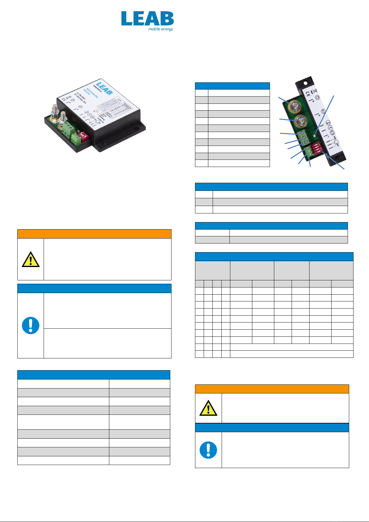
Example: DIP switch
with setting 0000
1. Disconnect the battery from the vehicle
power circuit.
Warning: Disconnect the negative lead first.
2. Set the desired switch-off voltage on the
DIP switches ().
3. Connect 'ground' () to the negative
terminal of the battery.
Notice: Only the switching current (1 A) is permissible. The consumer
load must not lead via the 'ground’ plug contact ().
4. Disconnect the positive lead from the battery to the consumers and
connect the battery watch at the screw terminals
() and ().
5. Connect the battery to the vehicle power circuit.
The BW 801e is ready for operation. When the battery voltage is
sufficient, the operating indicator () lights green.
Optional Activities:
Connect an external buzzer via the ‘alarm output’ ().
Notice: Contact to ground, max. 1 A.
To use the battery watch as the main switch for the connected
consumers, lay a wire with a switch between the negative pole of the
battery and the ‘external switch’ connector ().
To connect the supplied LED,
carry out the following steps:
1. Attach the anode for green (shortest
leg) with connector ().
2. Attach the cathode (longest leg)
with connector ().
3. Attach the anode for red
with connector ().
The 3-colour LED is connected.
5. Operation
The operating status of the device is shown by the operating indicator (),
the 3-colour LED, the alarm output () and the internal buzzer.
The following table shows the operating status:
Battery voltage is above the alarm threshold
setting, device is active.
External switch () is closed, consumers are
switched off.
Safety level 1: Below alarm threshold. Battery
voltage will soon reach the switch-off voltage.
Switch the consumers off or charge the
battery.
Internal buzzer:
Beep (interval*)
Safety level 2: Below switch-off voltage.
Consumers have been disconnected from the
battery to avoid deep discharge.
To supply consumers again, charge the
battery to the switch-on voltage.
Internal buzzer:
Beep (1x)
Device is switched off or incorrectly installed.
*Internal buzzer interval (in seconds): 600 –300 –150 –75 –37 –18 –9.
After that: Beep every 9 seconds until reaching the switch-off voltage.
6. Decommissioning
To remove the BW 801e, perform the following steps:
1. Disconnect the battery from the vehicle power circuit.
Warning: Disconnect the negative lead first.
2. Remove the leads on the connectors (, , , and ) from the
vehicle.
3. Remove the device from the vehicle.
The device is now removed.
7. Disposal
Dispose of the device in accordance with the Waste of Electrical and
Electronic Equipment Regulations (WEEE).
The device must not be disposed of with household waste. Take
it to a recycling point or send it to your point of sale.
8. EU Declaration of Conformity
The product
BW 801e
complies with the requirements of the following guidelines:
2014/30/EU : EMC
2011/65/EU : RoHS
9. Warranty
LEAB grants a legal guarantee from the date of purchase if the installation of
the product has been carried out by a specialist and if it has been used in
accordance with the intended use.
If defects or malfunctions occur during normal use within this time, LEAB will,
at its discretion, repair or replace the device free of charge.
Requirements for the completion of work under warranty are:
Invoice or delivery note
Model name or type
Serial number
Detailed description of the fault and the installation
Note the serial number and the purchase date here.
The serial number is printed on the product label.
LEAB Automotive GmbH
Thorshammer 6
D-24866 Busdorf
It is prohibited to copy, duplicate, translate or otherwise pass on the content of this
guide to third parties without the express written permission of LEAB Automotive
GmbH.