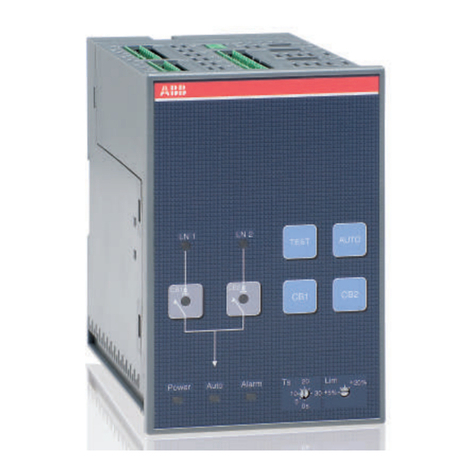
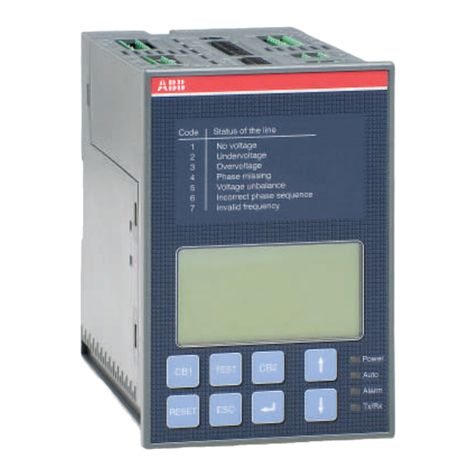
ABB ATS022 User manual

Automatic transfer switch ATS022
Doc. No. 1SDH000760R0002 - L8884
Installation and operating instructions


Installation and operating instructions, ATS022
3
1SDH000760R0002
Contents
Contents
1. Safety notes ....................................................................................................................... 4
2. Explanation of abbreviations and terms ......................................................................... 5
2.1. General information.......................................................................................................................5
2.2. Times.............................................................................................................................................5
3. Introduction........................................................................................................................ 6
3.1 Product overview...........................................................................................................................6
3.2 Application scenarios ................................................................................................................... 7
4. Applications of device ATS022......................................................................................... 8
4.2 Switching Main Line – Emergency generator (2CBs) ....................................................................9
4.3 Non priority loads control (NPL) ..................................................................................................10
4.4 Control of two independent power supply lines separated by Tie (3CBs Bus Tie).....................14
4.5 Automatic switching without inverse procedure .........................................................................15
4.6 Line Priority Selection.................................................................................................................16
5. Using the automatic transfer switch ............................................................................. 17
5.1 Interface.......................................................................................................................................17
5.2 LED indicators ............................................................................................................................. 18
5.3 Keypad keys................................................................................................................................19
5.4 Setting the operating modes.......................................................................................................20
5.4.1 Manual mode...............................................................................................................................20
5.4.2 Automatic mode .......................................................................................................................... 20
5.5 Graphic Display ........................................................................................................................... 21
5.5.1 LN1 and LN2 lines status indication............................................................................................22
5.5.2 Browsing through the Menu ........................................................................................................22
5.6 Using pushbuttons in manual mode ...........................................................................................26
5.7 Test Modes ..................................................................................................................................27
5.8 Modbus Communication.............................................................................................................28
5.8.1 Local / Remote Configuration ..................................................................................................... 28
6. Input and output signals ................................................................................................. 29
6.1 Output signals (DO1…DO12) ......................................................................................................29
6.2 Input signals ............................................................................................................................... 31
7. Technical data.................................................................................................................. 38
8. Installation of device ATS022 ......................................................................................... 39
8.1. Door-mounted Automatic Transfer Switch ATS022....................................................................39
8.2. DIN rail-mounted Automatic Transfer Switch ATS022.................................................................40
9. Regulatory standards...................................................................................................... 41
10. Troubleshooting............................................................................................................... 42
1SDH000760R0002 4
Installation and operating instructions, ATS022 1. Safety notes
1. Safety notes
If there are doubts about safe use, the unit must be put out of service.
The automatic transfer switch ATS022 must be prevented from operating the circuit breakers before:
• accessing the circuit breakers
• performing maintenance on circuit breakers or any electrical circuits powered by them
• performing any operation where opening/closing the circuit breaker could be dangerous
During maintenance:
• set the "Manual" mode.
• lock the circuit breaker mechanically in the open position.
Safe use is not guaranteed if:
• the device has been damaged during transport
• the device shows visible signs of damage
• the device does not work
• the device has been stored for a long period
Even if the device seems to be in stand-by status switch it off from the control circuit, as there is risk of it
operating the circuits without warning.
Before using the ATS022 unit, read the following “Safety notes”:
using the unit without following the indications can lead to malfunctioning and, in
some cases, hazardous conditions.

Installation and operating instructions, ATS022
5
1SDH000760R0002
2. Explanation of abbreviations and terms
2.1. General information
ATS: Automatic Transfer Switch; automatic switching device.
ATS022: ATS of the ATS02x series, version with display and Modbus communication.
CB: Circuit Breaker; low voltage automatic Circuit Breaker.
CB1: CB on line LN1.
CB2: CB on line LN2.
CB3: CB for Bus Tie, NPL and NPL BUS TIE operating modes.
LN1: Power supply line No.1.
LN2: Power supply line No.2.
Bus Tie: Operating mode with busbar tie circuit breaker.
NPL: Operating mode with non priority control circuit breaker.
NPL BUS TIE: Operating mode with non priority control circuit breaker for non priority loads control.
Modbus RTU: Communication protocol.
2.2. Times
NOTE: All the details of the times and switching logics are described in the Chapters concerned.
TS: - Opening delay of main line CB, after detection of fault in mains (generator is not in
use).
- Generator start delay, after detection of fault in mains (generator in use).
TCE: Closing delay of CB2 of line LN2.
TBS: Opening delay of emergency line CB, after detection of stabilised voltage on main line.
TCN: Closing delay of CB1 of line LN1.
TGOFF: Generator switching off delay, after closure of main line CB.
TC: Delay in opening and closing of CB3 in Bus Tie application.
TL Delay in activation of outlet DO7, after detection of the fault on both lines LN1 and
LN2.

1SDH000760R0002 6
Installation and operating instructions, ATS022
3. Introduction
3.1 Product overview
The automatic transfer switch ATS022 is used in all installations where switching is required between two
lines to ensure the supply of loads in case of a fault on one line.
ATS022 selects the power supply line by acting directly on the CBs provided on the lines: ATS022 can be
used with automatic CBs and ABB SACE switch-disconnectors.
The device monitors the voltage of the main line and emergency line and records the following faults:
• Maximum and minimum voltage
• Maximum and minimum Frequency
• Phase balance
• Voltage imbalance
• Frequency imbalance
ATS022 does not require an auxiliary safety power supply since it is powered directly by the line
voltages.
If both lines are absent, ATS022 enters Powersave mode (maximum duration 1 minute) in which the
device is active and in stand-by for one of the power supply lines to be restored. When the Powersave
period ends, the LED switches off and the device awaits a line voltage. The moment the main or the
emergency line is restored, the unit analyses the conditions of the lines monitored and the status of the
circuit breakers and proceeds with the switching operation in accordance with the situation concerned.
The safety auxiliary supply is obligatory in the following cases:
• utilisation of Modbus RS485 communication
• utilisation in systems with rated frequency 16 2/3Hz
• utilisation in single-phase systems with Un 57,5…109VAC
A 24VDC ….110VDC auxiliary safety power supply can be used (-10%, +15%).
ATS022 can be used in systems with rated frequency 50Hz, 60Hz, 400Hz, 16 2/3 Hz that can be set from
the menu.
The device can be used in systems with single-phase, three-phase with Neutral and three-phase
without neutral, setting can be done from the menu. ATS022 makes it possible to select from the display
a different distribution system between Line LN1 and Line LN2. ATS022 can be used in manual or
automatic mode. In the first case the circuit breakers must be controlled by means of the pushbuttons
present on the front panel of the device, while in automatic mode, the switching logic is controlled
directly by the device
The device is equipped with a front graphic display by means of which the user can check the settings
and display the status of the unit and the circuit breakers connected to it.
It is also possible to integrate the ATS022 device inside a communication network which uses the
Modbus RS485 protocol.
3. Introduction

Installation and operating instructions, ATS022
7
1SDH000760R0002
3.2 Application scenarios
The ATS022 device can be used in the following applications:
• Main line – Emergency line switching
• Main line – Emergency generator switching
ATS022 makes it possible to operate a thrid circuit breaker CB3 and can therefore also be used in the
following applications which can be set on the menu:
• non priority loads control with CB3 on starting line (3CBs NPL)
• non priority loads control with CB3 Bus Tie (3CBs NPL Bus Tie)
• control of two independent power supply lines separated by Bus Tie (3CBs Bus Tie)
The ATS022 also makes it possible to select which of the lines is the main one and which one is
secondary, also with the system running.
The following selections are possible, set from the menu:
• Main line: Line LN1
• Main line: Line LN2
• No priority line
In automatic mode, it is possible to select whether or not the switching procedure must include inverse
switching.
The following selections are possible:
• with inverse procedure
• without inverse procedure
3. Introduction

1SDH000760R0002 8
Installation and operating instructions, ATS022
4. Applications of device ATS022
The ATS022 device controls all the switching sequences by applying the time delays that can be set:
Time delays Description Value
TS Delay
Opening delay of main line CB after detection of a fault in the
mains (Generator is not in use). 0…30s
Generator start delay after detection of a fault in the mains
(Generator in use).
TBS Delay Opening delay of emergency line CB. 0…59s, 1,2,3…30min
TCE Delay Closing delay of line LN2 CB2. 0…60s
TCN Delay Closing delay of CB1 of line LN1. 0…60s
TC Delay Opening and closing delay of CB3 if used in Bus Tie
application. 0…60s
TGOFF Delay Generator switching off delay after closure of line LN1 CB1. 0…59s, 1,2,3…30min
TL Delay Delay in activation of outlet DO7, after detection of the fault
on both lines LN1 and LN2. 0...60s
Table 4.1: Description of time delays
ATTENTION: it is necessary to take into consideration that the total switching time, in addition to the set
up delay, includes also the internal time of ATS.
4.1 Switching Main Line – Emergency Line (2CBs)
Description
Both lines are normally present; in cause of anomaly on the main line,
ATS022 switches to the emergency line used as the reserve line.
KA00428
Figure 4.1: 2CBs application layout – generator not in use
4. Applications of device ATS022

Installation and operating instructions, ATS022
9
1SDH000760R0002
Time diagrams
TS TCE TBS TCN
Line 1 ok
CB1 CLOSED
Line 2 ok
CB2 CLOSED
Figure 4.2: 2CBs application time diagram - main line LN1
Special cases: if LN1 returns to normal during TS, the changeover is interrupted; if LN1 returns to
normal during TCE, the changeover is completed. If LN1 disappears during TBS, the changeover is
interrupted; if LN1 disappears during TCN, the changeover is completed. If LN2 is absent, after TS the
unit waits for the presence of LN2 in order to send the opening command to CB1. If LN2 disappears
during TCE, the procedure is in any case completed.
4.2 Switching Main Line – Emergency generator (2CBs)
Description
In case of main line failure ATS022 automatically starts up an emergency generator and, as soon as
power on the generator side is available, ATS022 starts the automatic switching procedure.
G
KA00427
Figure 4.3: 2CBs application layout – generator in use
4. Applications of device ATS022

1SDH000760R0002 10
Installation and operating instructions, ATS022
Time diagrams
Line 1 ok
CB1 CLOSED
Gen start
Line 2 ok
CB2 CLOSED
TS TCE TCNTBS TGOFF
Figure 4.4: 2CBs application time diagram - generator in use
Special cases: if LN1 returns to normal before LN2, the sequence is interrupted and the generator is
turned off; if LN1 returns to normal during TCE, the sequence is completed. If LN1 disappears during
TBS, the sequence is interrupted; if LN1 disappears during TCN, the switchboard starts TS running in
order to re-enter on LN2. If LN2 disappears during TCE, the procedure is in any case completed.
4.3 Non priority loads control (NPL)
Description
In case of main line failure the ATS022 starts the switching procedure and controls the non priority loads
by opening closing circuit breaker CB3.
ATS022 acquires the CB3 open/close status from the dedicated input DI11 and commands the opening
and closing by activating output DO11.
The application of non priority loads requires the use of two CT-AWE typed timed relays for operating the
opening and closing of CB3.
Two configurations are possible for utilisation depending on the position of circuit breaker CB3:
• CB3 in Bus Tie position (3CBs NPL – BUS TIE)
• CB3 on starting line (3CBs NPL).
It is possible to select from two options from the menu on the display for the 3CBs NPL - Bus Tie
configuration:
• only disconnection of non priority loads by opening CB3 (manual re-closure). In this case timed relays
CT-AWE are not necessary
• disconnection and re-connection of non priority loads by opening and closing of CB3
For more details refer to the wiring diagrams of the product.
Usage notes: the NPL loads are always combined with line LN1: configuring the unit without a priority
line or with LN2 as the priority line does not change the way changeover of CB3 is managed. NPL
4. Applications of device ATS022

Installation and operating instructions, ATS022
11
1SDH000760R0002
configuration requires configuration with 2 lines or with a line and an emergency generator.
CB1 CB2
CB3
NPL
Figure 4.5: Application layout 3CBs NPL BUSTIE
CB1 CB2
CB3
NPL
Figure 4.6: Application layout 3CBs NPL
4. Applications of device ATS022

1SDH000760R0002 12
Installation and operating instructions, ATS022
Time diagrams
TS TCE TBS TCN TGOFF
Line 1 ok
CB1 CLOSED
Gen start
Line 2 ok
CB2 CLOSED
CB3 CLOSED
Figure 4.7: Application time diagram 3CBs NPL BUS TIE - generator in use
Line 1 ok
CB1 CLOSED
Line 2 ok
CB2 CLOSED
CB3 CLOSED
TS TCE TCNTBS
Figure 4.8: Application time diagram 3CBs NPL BUS TIE - generator not in use
Special cases: if LN1 returns to normal before LN2, the sequence is interrupted and the generator is
switched off; if LN1 returns to normal during TCE, the sequence is completed. If LN1 disappears during
TBS, the sequence is interrupted; if LN1 disappears during TCN, the switchboard starts TS running in
order to re-enter on LN2. If LN2 disappears during TCE, the procedure is in any case completed. main
line LN1.
4. Applications of device ATS022

Installation and operating instructions, ATS022
13
1SDH000760R0002
TGOFF
Line 1 ok
CB1 CLOSED
Line 2 ok
Gen start
CB2 CLOSED
CB3 CLOSED
TS TCE TCNTBS
Figure 4.9: Application time diagram 3CBs NPL- generator in use
TCE
Line 1 ok
CB1 CLOSED
Line 2 ok
CB2 CLOSED
CB3 CLOSED
TS TCNTBS
Figure 4.10: Application time diagram 3CBs NPL - generator not in use - main line LN1
Special cases: if LN1 returns to normal before LN2, the sequence is interrupted and the generator is
switched off; if LN1 returns to normal during TCE, the sequence is completed. If LN1 disappears during
TBS, the sequence is interrupted; if LN1 disappears during TCN, the switchboard starts TS running in
order to re-enter on LN2. If LN2 disappears during TCE, the procedure is in any case completed.
4. Applications of device ATS022

1SDH000760R0002 14
Installation and operating instructions, ATS022
4.4 Control of two independent power supply lines
separated by Tie (3CBs Bus Tie)
Description
Lines LN1 and LN2 supply two different sections of the plant separated by a bus tie circuit breaker CB3,
normally open. In case of failure of one of the two supply lines, ATS022 closes CB3; the available line
thus powers both the sections downline. When the line is restored ATS022 restores the normal plant
conditions by opening CB3. ATS022 acquires the open/close status of the device by means of dedicated
input DI11 and commands the opening and closing by activating output DO11. The Bus Tie application
requires the use of two CT-AWE type timed relays for operating the opening and closing of CB3. The
three circuit breakers CB1 – CB2 – CB3 must be interlocked mechanically for reasons of safety (Emax
circuit breakers – C type interlock).
CB1 CB2
CB3
Figure 4.11: Application layout 3CBs BUS TIE
Time diagrams
Line 1 ok
CB1 CLOSED
Line 2 ok
CB2 CLOSED
CB3 CLOSED
TS TC TCNTBS
Figure 4.12: Application time diagram 3CBs BUS TIE – line LN1 failure
Special cases: if LN1 returns to normal during TS, the changeover is interrupted; if LN1 returns to
normal during TC, the changeover is completed. If LN1 disappears during TBS, the changeover is
interrupted; if LN1 disappears during TCN, the changeover is completed. If LN2 disappears during TS,
the changeover is interrupted. If LN2 disappears during TC, the changeover is completed.
4. Applications of device ATS022

Installation and operating instructions, ATS022
15
1SDH000760R0002
Line 1 ok
CB1 CLOSED
Line 2 ok
CB2 CLOSED
CB3 CLOSED
TS TC TCNTBS
Figure 4.13: Application time diagram 3CBs BUS TIE – line LN2 failure
4.5 Automatic switching without inverse procedure
Description
Following an anomaly of the main line, ATS022 switches on an emergency line (1). If the mains supply
is restored, the inverse switching procedure is not started up (2). If there is a fault in the reserve line,
ATS022 must open the emergency switch (3) and wait for restoration of the emergency line to reclose (4),
without in any case providing for switching on the main line. This operating mode is also applicable if the
generator is present: in this case, after time Ts the generator is started up and as soon as the emergency
line is available CB1 is opened.
ATTENTION If ATS022 is not powered by the auxiliary supply and by any of the two lines the device
waits for at least one of the two lines (5) to return before proceeding with the switching procedure (6).
The option is not available in case of 3CBs Bus Tie application and in case of selection of the no priority
line option.
Time diagrams
TS TBS TCE
TCE TBS
(1) (2) (3) (4) (5) (6)
Line 2 ok
CB2 CLOSED
Line 1 ok
CB1 CLOSED
Figure 4.14: 2CBs application time diagram - generator not in use – without inverse switching procedure
4. Applications of device ATS022

1SDH000760R0002 16
Installation and operating instructions, ATS022
4.6 Line Priority Selection
Description
ATS022 allows selection of the main line by means of the menu on the display. The following selections
are possible:
- main line: Line LN1
- main line: Line LN2 (selection possible only if generator is not in use)
- no line priority: ATS022 ensures power supply to the load from any of the two lines without
considering either of these as priority, therefore, for example, following switching on line LN2 due
to failure of line LN1, ATS022 remains on line LN2 even if LN1 is restored.
Time diagrams
Line 1 ok
CB1 CLOSED
Line 2 ok
CB2 CLOSED
TS TCE TBS TCN
Figure 4.16: Time Diagram no line priority – generator non in use
Line 1 ok
CB1 CLOSED
Gen start
Line 2 ok
CB2 CLOSED
TS TCE
Figure 4.17: Time diagram no line priority – generator in use
4. Applications of device ATS022

Installation and operating instructions, ATS022
17
1SDH000760R0002
5. Using the automatic transfer switch
5.1 Interface
Code
1
2
3
4
5
6
7
Status of the line
No voltage
Undervoltage
Overvoltage
Phase missing
Voltage unbalance
Incorrect phase sequence
Invalid frequency
RESET
ATS022
M3010004A
16
15
14
10
11
97 34 86
12
1
5
2
13
Figure 5.1: Description of ATS022 front panel interface
Ref. Description
1 CB1: pushbutton for opening/closing circuit breaker CB1
2 CB2: pushbutton for opening/closing circuit breaker CB2
3 CB3: CB3 opening/closure procedure graphic indication (combination of UP-DOWN keys for at
least 2sec)
4 RESET: pushbutton for automatic/manual mode selection and alarms reset
5 TEST: test modes selection pushbutton
6 ENTER: pushbutton for confirming an action
7 ESC: pushbutton for returning to the previous step
8 UP: pushbutton for moving up on the menu
9 DOWN: pushbutton for moving down on the menu
10 LED POWER: indicates presence of power supply
11 LED AUTO: indicates automatic or manual mode
5. Using the automatic transfer switch

1SDH000760R0002 18
Installation and operating instructions, ATS022
Ref. Description
12 LED ALARM: indicates active alarm
13 Tx/Rx LED: indicates bus communication status
14 GRAPHIC DISPLAY
15 PLATE SHOWING LINES STATUS CODES
16 Serial No.
Table 5.1: Description of ATS022 interface
5.2 LED indicators
Alarm
The steady red Alarm LED may indicate the switching logic disabled condition or one of the following
events:
• circuit breakers command failed
• protection releases tripped
• removal of circuit breakers
• generator alarm
• logic disabling from input DI3
• CBs closed (2 or 3 depending on the configuration)
The alarm LED switches Off indicating that the switching logic is enabled and no alarms are present
Auto
The Auto LED indicates the operating mode:
• manual: LED Off
• automatic: steady green LED
• test: flashing green LED
Power
LED Power LED indicates the presence of power supply:
• power supply present: steady green LED indicates power supply from line voltage or from auxiliary
source present
• no power supply: LED Off indicates that both lines are not present and that the Powersave condition
has ended. The switching logic is in stand-by for return of one of the line voltages
• Powersave: green flashing LED indicates, if both lines are absent and if no auxiliary power supply is
present, that the device is active and is in stand-by for return of one of the line voltages (maximum
duration 1 minute). When the Powersave period ends, the LED switches off and the device awaits
a line voltage. The moment the normal or the emergency line is restored, with ATS022 in automatic,
the unit analyses the conditions of the lines monitored and the status of the circuit breakers and
proceeds with the switching operation in accordance with the situation concerned.
TX/RX
The TX/RX LED indicates the bus communication status.
• Communication via bus under way: green LED flashing at variable frequency
• Communication via bus not active: LED Off
5. Using the automatic transfer switch

Installation and operating instructions, ATS022
19
1SDH000760R0002
5.3 Keypad keys
CB1 key
In manual mode, press the CB1 key for Opening/Closure of circuit breaker CB1.
CB2 key
In manual mode, press the CB2 key for Opening/Closure of circuit breaker CB2.
RESET
Press RESET to select the Manual or Automatic operating mode.
In case of alarm, press RESET to reset the alarm and the device returns to manual mode. Press RESET
again to bring the device to automatic mode.
TEST key
Press the TEST key to set the test modes of the
direct and inverse switching sequences.
ATS022 must be in the manual position. To exit TEST mode press
RESET.
Enter key
Used for confirming the action or entry to the menu.
ESC key
Used for cancelling an action and returning to previous menu.
UP key
Used for moving up on the menu.
DOWN key
Used for moving down on the menu.
5. Using the automatic transfer switch

1SDH000760R0002 20
Installation and operating instructions, ATS022
5.4 Setting the operating modes
5.4.1 Manual mode
To select the Manual operating mode of unit ATS022:
a. Make sure the Power LED is On, see Figure 5.2/1
b. If the Auto LED is OFF, see Figure 5.2/2, the automatic transfer switch is in Manual mode.
c. If the AUTO LED is ON, press RESET, see Figure 5.2/3 . The Auto LED switches to OFF and the
device is in Manual Mode, see Figure 5.2/4 .
OR
KA00345IT
Manual mode
Manual mode
!
TEST
CB1 CB2
!
1 2
2 3 4
Figure 5.2: Description of manual mode selection procedure for ATS022
5.4.2 Automatic mode
To select the Automatic operating mode of unit ATS022:
a. Make sure the Power LED is On, see Figure 5.3/1
b. Press RESET once, see Figure 5.3/2. If the Auto LED is ON, the automatic transfer switch ATS022 is
in Automatic mode, see Figure 5.3/3
c. If the Auto LED is OFF, press RESET again, see Figure 5.3/3; the Auto LED switches to ON and the
device is in Automatic mode/ Figure 5.3/4
KA00347IT
OR
!
TEST
CB1 CB2
Automatic Mode
TEST
CB1 CB2
!
Automatic Mode
1 2 3
345
Figure 5.3: Description of automatic mode selection procedure for ATS022
5. Using the automatic transfer switch
Other manuals for ATS022
1
Table of contents
Other ABB Switch manuals

ABB
ABB DS1 User manual

ABB
ABB TruONE ATS OXB250E3S3QT User manual

ABB
ABB SACE Tmax XT User manual

ABB
ABB Zenith ZTX Series User manual

ABB
ABB MKey8M User manual

ABB
ABB Zenith ZTG Series User manual

ABB
ABB Uniswitch User manual

ABB
ABB NE840 User manual

ABB
ABB OTM3200E4230C-GE User guide

ABB
ABB Sense7 Series User manual

ABB
ABB F-400 User manual

ABB
ABB SSM/A User manual

ABB
ABB EDS500 Series User manual

ABB
ABB OTM_C Series User guide

ABB
ABB SACE Tmax XT User manual

ABB
ABB 3299E-A32100 User manual

ABB
ABB UniSec SDS Operating and maintenance instructions

ABB
ABB LMS100 Series Instruction Manual

ABB
ABB FAP 1001 User manual

ABB
ABB VUBB User manual