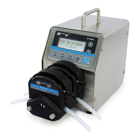
LEAD FLUID BQ80S User manual

BQ80S Micro flow Variable-Speed Peristaltic Pump
Operation Manual
BAODING LEAD FLUID TECHNOLOGY CO.,LTD.

Safety Cautions
Danger: Please use correct AC power voltage source shown on
the sticker on the equipment to avoid any damage.
Please do not open the case. It may cause malfunction or electric
shock.
For maintenance, please contact the manufacture or distributor directly.
Danger: To install or remove pump head, please turn off the power supply
first. Do not touch the rolling roller with hands or cloth.
Warning: Tubing breakage may result in fluid being sprayed from
pump. Use appropriate measures to protect operator and
equipment.
Warning: Remove power from the pump before attempting any
maintenance or any cleaning operation is started.
Warning: Remove power from pump before connecting or disconnecting
the external control device or communication interface.
Warning: This product is not designed for, nor intended for use in patient
connected applications; including, but not limited to, medical and dental
use.

Contents
1 Introduction.........................................................................................................1
2 Functions and Features....................................................................................1
3 Components and Connectors..........................................................................2
4 Display Panel and Operating Keypads..........................................................3
4.1 Keypad.....................................................................................................3
4.2 Digital Display......................................................................................4
4.3 External Control......................................................................................5
5 Operation Instructions.......................................................................................6
5.1 Before Operation....................................................................................6
5.2 Tube installation......................................................................................6
5.3 Power Connection..................................................................................7
5.4 Control Mode ..........................................................................................7
5.5 Communication Mode..........................................................................12
5.6 Footswitch Mode..................................................................................13
6 Maintenance.....................................................................................................14
6.1 Warranty................................................................................................14
6.2 Regular Maintenance ..........................................................................14
6.3 Malfunction Solutions ..........................................................................14
7 Dimensions.......................................................................................................16
8 Naming Rule.....................................................................................................17
9 Specifications...................................................................................................17
10 Suitable Pump Heads and Tubing..............................................................18
11 Input Output Signal Parameter....................................................................18

BQ80S Micro Flow Variable-Speed Peristaltic Pump
1 Introduction
BQ80S is a portable micro flow variable-speed peristaltic pump. It provides
flow range from 0.005 to 64 mL/min with variable pump heads and tubing. It
offers not only basic functions such as start/stop, reversible direction and
adjustable speed, but also Time Dispense Mode to dispense fluid by setting
the duration time for each dose. With standard RS485 MODBUS interface,
it is easy to communicate with external device, such as PC, HMI or PLC.
2 Functions and Features
•Simple operation, portable size, easy to install. Suitable for
equipment as an ancillary device and for laboratory use.
•0.5% high precision rotating speed control with 0.1 rpm speed
resolution. Speed range 0.1-80 rpm.
•Four-digit LED displays working speed and control mode.
•Membrane keypad.
•Reversible direction, start/stop, adjustable speed.
•Time dispense function. Repeat dispensing by setting the dispense
duration time.
•Plastic housing, embedded design to work independently.
•The circuit board with conformal coating makes it dust-proof and
moisture-proof.
•External logic level signal can control start/stop, reversible direction
and time dispense function. The control signal is optically isolated.
•External logic level signal: 5V (default), 12V or 24V.
•MODBUS RS485 interface, easy to communicate with external
control devices.
•Optional footswitch or timer for dispensing fluid.
1 Tel:0312-3250677 3250877 3250977 Fax:0312-3250877-804

BQ80S Micro Flow Variable-Speed Peristaltic Pump
4 Display Panel and Operating Keypads
MODE
Pump Head
UP/DOWN
DIRECTION
DISPENSE
START/STOP
Digital LED
Display 8888
Figure 2. Display panel
4.1 Keypad
UP key. Press once, the last digit of the speed number will increase
1. Press and hold the key to increase the number quickly.
DOWN key. Press once, the last digit of the speed number will
decrease1. Press and hold the key to decrease the number quickly.
MODE key. Change operation mode: Internal Control Mode,
External Control Mode, Time Dispense Mode and Logic Level
Control Mode. This key is disabled when drive is running.
DIRECTION key. Switch the direction between clockwise and
counterclockwise.
DISPENSE key.When on Internal Control or Dispense mode, press
it shortly to start dispensing. Press and hold the key to set the
dispense time.
START/STOP key. Press the key shortly to start or stop the drive.
Press and hold the key to run the drive at full speed.
MODE
3 Tel:0312-3250677 3250877 3250977 Fax:0312-3250877-804

LEAD FLUID TECHNOLOGY CO.,LTD.
4.2 Digital Display
The LED display shows the current rpm and working mode.
3.5
Figure 3. Internal Control Mode, 3.5 rpm, clockwise
. 4.5
Figure 4. Internal Control Mode, 4.5 rpm, counterclockwise
E1.5
Figure 5. External Control Mode, 1.5 rpm, clockwise
f21.5
Figure 6. TimeDispense Mode, 21.5 rpm, clockwise
H31.5
Figure 7. Logic Level Control Mode (high/low), 31.5 rpm, clockwise
C11.5
Figure 8. When flashing, it’s to set dispense time
dispense time=11.5 seconds
Mail:master@leadfluid.com WEB:www.leadfluid.com 4

BQ80S Micro Flow Variable-Speed Peristaltic Pump
FUll
Figure 9. Full Speed
4.3 External Control
1 2 3 4 5 6 7 8
910 11 12 13 14 15
Figure 10. DB15 Connector for External Control
Table 1. DB15 Connector
DB15
Mark Note
1
ADC_W
Positive of external analog input
2 B Communication interface, B pole of RS485
3 A Communication interface, A pole of RS485
4 VCC_W External DC input
5
6 CW_W External direction control input
7
8 COM Ground of external power
9 AGND Negative of analog signal input
10 +12V Positive of internal +12V power source
11
GND
Ground of Internal power source
5 Tel:0312-3250677 3250877 3250977 Fax:0312-3250877-804

LEAD FLUID TECHNOLOGY CO.,LTD.
12
13 RS_W External start/stop signal input terminal
14
15
5 Operation Instructions
5.1 Before Operation
1) Please check the packing slip to make sure nothing is wrong or
damaged in the package. If there is problem, please contact the
manufacturer or distributor.
2) Read through the instruction.
3) There should be more than 200 mm space for the back of the pump
when it is running.
5.2 Tube installation
Please check pump head manual before installation
DW Pump Head
1) Open the lever on the right side of the pump head , lift up the block;
2) Take the tube (according to the use of the length of the interception),
one end into the aluminum frame on the left side of the fixed slot, and then
through the top of the roller body put the other end of the card on the right
side of the corresponding fixed slot, both ends of the sleeve use stopper to
tighten.
3) Adjust the tube in smoothly , and the block back in situ, reset adjusting
lever.
4) Depending on the thickness of the wall, inner diameter, material and
work condition adjust pressure nut into the appropriate position, must not
Mail:master@leadfluid.com WEB:www.leadfluid.com 6

BQ80S Micro Flow Variable-Speed Peristaltic Pump
be excessive pressure for the tube.
FZ Pump Head:
1) Lift the cover to move the block up
2) Take 100mm long tube, set into the roller assembly
3)Adjustment tube of pump head, straighten the hose inside the pump
head, with both hands tighten the hose ends, so that the natural stretch, no
distortion, no skew.
4) Press down the cover then finish the tube installation.
5.3 Power Connection
Pump comes with a power adapter. Plug the power supply connector to the
power input jack on the rear of the pump.
5.4 Control Mode
21.5E0.0
F21.5
H21.5
Internal Control Mode External control Mode
Easy Dispense Mode
Logic Level Control Mode
MODE
MODE
MODE
MODE
Figure 11. Control Mode Switch
5.4.1 Internal Control Mode
On this mode, use the keypad to operate the pump.
1) Turn on the power switch. The digital LED display will be on.
2) Press MODE key to change the control mode to internal control.
3) Press UP/DOWN key to adjust the rotating speed.
4) Press DIRECTION key to change the rotation direction if necessary.
7 Tel:0312-3250677 3250877 3250977 Fax:0312-3250877-804

LEAD FLUID TECHNOLOGY CO.,LTD.
21.5.21.5
Figure 12. Change Rotating Direction
5) Press START/STOP key to start or stop the drive.
6) Press and hold the START/STOP key will make the drive run at full
speed.
21.5 fUll
Hold
Figure 13. Full Speed
5.4.2 External Control Mode
On this control mode, the external 0-5V, 0-10V or 4-20mA analog signal
controls the speed, voltage signal 5V, 12V or 24V controls start/stop. The
keypad is disabled.
1) Turn the power off. Wire the external signal as shown on Figure 14 or
Figure 15, and connect DB15 connector to the DB15 port on the rear of
pump.
1 2 3 4 5 6 7 8
9 10 11 12 13 14 15
ADC_W AGND
0-5V/0-10V
/4-20mA 12VDC
VCC_W COM
RS_W
CW_W
Figure 14. External Controlwith External 5V or 12VDC Power Source
Mail:master@leadfluid.com WEB:www.leadfluid.com 8

BQ80S Micro Flow Variable-Speed Peristaltic Pump
1 2 3 4 5 6 7 8
910 11 12 13 14 15
ADC_W AGND
0-5V/0-10V
/4-20mA
RS_W
CW_W
Figure 15.External Control with Internal 12VDC Power Source
2) Turn on the power switch. The digital LED display will be on.
3) Press MODE key to change the control mode to external control mode.
The external analog signal could be 0-5V, 0-10V or 4/20mA. By default,
the signal is 0-5V. For 0-10V or 4-20mA, the jump setting on the analog
signal control board has to be changed (Figure 16).
0-5V (default)
0-10V
4-20mA
Figure 16. Analog Signal Control Board Setting
4) When RS_W switch is closed and the analog control signal is provided,
the rotating speed of the drive will change according to the intensity of
the analog control signal. When RS_W switch is open, the drive will
stop running.
When CW_W is open, the drive will run in clockwise direction; when
CW_W is closed, the drive will run in counterclockwise direction.
9 Tel:0312-3250677 3250877 3250977 Fax:0312-3250877-804

LEAD FLUID TECHNOLOGY CO.,LTD.
E12.5
Drive Stopped Drive Running
E0
Figure 17. Drive Running State
Note: The external DC power source can be 5V or 12V. If it is 24V, 1.5K
resistor is needed to protect internal circuit.
Figure 18. DB15 Wiring with External 24VDC Power Source
5.4.3 Time Dispense Mode
On this mode, pump will dispense fluid by setting the duration for each
dose.
1) Turn on the power switch. The digital LED display will be on.
2) Press MODE key to change the control mode to Internal Control or
Time Dispense Mode.
3) Press and hold DISPENSE key for 3 seconds, the LED display will be
flashing. It is for setting the dispense time.
4) Press UP or DOWN key to change the dispense time, the range is from
0.1 to 999 seconds.
5) Press DISPENSE key again to exit the dispense time setting.
6) Press DIRECTION key to change the rotation direction if necessary.
7) Press DISPENSE key, pump will start to run for the set time then stop.
123 4 5 6 7 8
9 10 11 12 13 14 15
ADC_W AGND
0-5V/0-10V
/4-20mA 24VDC
VCC_W COM
RS_W
CW_W
1.5K
1.5K
Mail:master@leadfluid.com WEB:www.leadfluid.com 10

BQ80S Micro Flow Variable-Speed Peristaltic Pump
8) When drive is running, press the START/STOPkey to stop the process
anytime.
9) When on Time Dispense Mode, a foot switch can be used to start/stop
dispensing.
F21.5 C 2.5
Hold
Flashing
Figure 19. Set Dispense Time
5.4.4 Logic Level Control Mode
On this control mode, the voltage signal controls start/stop.
1) Turn the power off. Wire the external signal as shown on Figure 20 or
Figure 21, and connect DB15 connector to the DB15 port on the rear of
pump.
1 2 3 4 5 6 7 8
910 11 12 13 14 15
RS_W
Figure 20. Logic Level Control with Internal 12V Power Source
1 2 3 4 5 6 7 8
9 10 11 12 13 14 15
12VDC
VCC_W COM
RS_W
Figure 21. Logic Level Control with External 5V or 12V Power Source
11 Tel:0312-3250677 3250877 3250977 Fax:0312-3250877-804

LEAD FLUID TECHNOLOGY CO.,LTD.
2) Turn on the power switch. The LED display will be on.
3) Press MODE key to change the mode to Logic Level Control Mode.
H21.5
Figure 22. Logic Level Control Mode
4) Press UP/DOWN key to adjust the desired rotation speed.
5) Press DIRECTION key to change the rotation direction if necessary.
6) When RS_W switch is closed, the drive will run at the set speed. When
RS_W switch is open, the drive will stop running.
Note: If a dispense timer is used, the control mode should be set to this
Logic Level Control Mode.
5.5 Communication Mode
The RS485 interface supports standard MODBUS protocol. Pump can be
communicated with external device via the communication port. Please
refer to the Communication Instruction Manual for the parameters and their
addresses.
1) Turn the power off. Wire the DB15 connector as shown below, and
connect it to the DB15 port on the rear of pump. External DC power
source is recommend to avoid electrical interference.
1 2 3 4 5 6 7 8
910 11 12 13 14 15
12VDC
VCC_W COM
B
A
Figure 23. RS485 Communication Wiring
Mail:master@leadfluid.com WEB:www.leadfluid.com 12

BQ80S Micro Flow Variable-Speed Peristaltic Pump
2) Turn on the power switch. The digital LED display will be on.
3) Press MODE key to change the control mode to Internal Control Mode
or Time Dispense Mode.
4) Control pump with communication interface.
5) Press the START/STOP key to stop the drive when necessary.
5.6 Footswitch Mode
On this mode, a footswitch is used to control start/stop.
1) Turn the power off. Wire the DB15 connector as shown below, and
connect it to the DB15 port on the rear of pump.
1 2 3 4 5 6 7 8
910 11 12 13 14 15
RS_W
Figure 24. Footswitch with Internal 12V Power Source
1 2 3 4 5 6 7 8
9 10 11 12 13 14 15
RS_W
DC12V
VCC_W COM
Figure 25. Footswitch with External 5V 0r 12V Power Source
2) Turn on the power switch. The digital LED display will be on.
3) Press MODE key to change the control mode to Internal Control Mode.
13 Tel:0312-3250677 3250877 3250977 Fax:0312-3250877-804

LEAD FLUID TECHNOLOGY CO.,LTD.
When the external switch RS_W is closed then open, the drive will
start to run. When the external switch RS_W is closed then open again,
the drive will stop running.
4) Press MODE key to change the control mode to Time Dispense Mode.
When the external switch RS_W is closed then open, pump will
dispense fluid once.
5) Press MODE key to change the control mode to Logic Level Control
Mode. When the external switch RS_W is closed, the drive will start to
run. When open, the drive will stop.
6 Maintenance
6.1 Warranty
The product comes with one-year labor and parts warranty. The limited
warranty does not cover any damage that is caused by improper usage and
handling.
6.2 Regular Maintenance
1) Always check the tubing and connections to make sure there is no
leakage.
2) Do not cover the fan in the back of the pump.
3) Do not use water to wash the pump. Keep pump head dry.
4) Do not use chemical solvents to clean pump and pump head.
6.3 Malfunction Solutions
No.
Malfunction
Description
Solution
1 Hardware No display 1. Check the power cord
2. Check the internal power cord
connection inside the pump.
2 Hardware Motor does
not work 1. Check the indicator of the driver
board.
Mail:master@leadfluid.com WEB:www.leadfluid.com 14

BQ80S Micro Flow Variable-Speed Peristaltic Pump
2. Check the wire connection
between the motor and the driver
board.
3 Hardware Motor is
trembling 1. Check the wire connection
between the motor and the driver
board.
2. The motor is overloaded. Check
the mechanical connection.
4 Hardware Keypad does
not work 1. Check the wire connection
between keypad and the main
board.
2. Check if the key is broken.
5 Hardware External
control does
not work
1. Check the wiring of the
connector.
2. Check if the external control
power voltage is provided.
3.Check the connections of the
external control board.
6 Hardware RS485 does
not work 1. Check the wiring of the
connector.
2. Check the connections of the
communication board.
7 Hardware Noisy
1. Check pump head installation
make sure it’s secure
2. Check the connection between
the motor and driver board.
8 Software External
control does
not work
Check if pump is on External
Control Mode.
9
Software
RS485 does
1. Reset the pump address.
15 Tel:0312-3250677 3250877 3250977 Fax:0312-3250877-804

BQ80S Micro Flow Variable-Speed Peristaltic Pump
8 Naming Rule
T
B100S
Drive Type
B: Step motor
W: DC brushless
motor
J: AC motor
F: Explosion Proof
Motor
Z: DC motor
165
Function Code
1-9 for special
pumps
Version
0-9
Rotation Speed
05: 50 rpm
08: 80 rpm
10: 150 rpm *
30: 350 rpm
60: 600 rpm
Flow Rate
Q: Microflow
T: Laboratory
G: Industrial
P: Batch transfer
IP rating
Default:
IP31
Pump type
D: Fixed speed
S: Variable speed
L: Flow pump
F: Dispensing
pump
* BT102S: 100 rpm
Figure 27 Naming Rule
9 Specifications
•Flow range: 0.005-64 mL/min
•Speed accuracy: 0.5%
•Speed range: 0.1-80 rpm
•Speed resolution: 0.1 rpm
•Power supply:AC 220V ± 10%, 50Hz/60Hz,AC 110V ± 10%,
50Hz/60Hz
•Power consumption: < 10W
•External logic level control signal: 5V, 12V (standard), 24V
(optional)
•External analog control signal: 0-5V (standard); 0-10V, 4-20mA
(optional)
•External communication interface: MODBUS RS485
•Ambient temperature: 0~40 °C
•Relative humidity: < 80%
•IP grade: IP31
17 Tel:0312-3250677 3250877 3250977 Fax:0312-3250877-804
Table of contents
Other LEAD FLUID Water Pump manuals
Popular Water Pump manuals by other brands

WaterAce
WaterAce R6S installation manual

Little Giant
Little Giant PE-2.5 Series quick start guide

WaterAce
WaterAce R106 installation manual

Master cool
Master cool 90063-2V-110-B operating instructions

Central Pneumatic
Central Pneumatic 93755 Owner's manual & safety instructions

Little Giant
Little Giant 15EC-CIA-SFS owner's manual