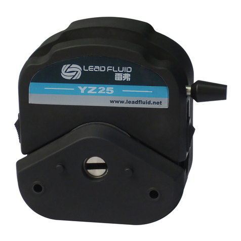
LEAD FLUID BT600S User manual

Operation Manual
For Basic Variable-Speed Peristaltic Pump
BT100S, BT300S, BT600S
BAODING LEAD FLUID TECHNOLOGY CO.,LTD

Safety Cautions
Danger: Please use correct AC power voltage source shown on
the sticker attached on the equipment to avoid any damage.
Please do not open the case. High voltages exist and are
accessible. Use extreme caution when servicing internal components.
For maintenance, please contact the manufacturer or distributor directly.
Danger: Turn drive off before removing or installing tubing. Fingers or loose
clothing could get caught in drive mechanism.
Warning: Tubing breakage may result in fluid being sprayed from
pump. Use appropriate measures to protect operator and
equipment.
Warning: Remove power from pump before attempting any maintenance or
any cleaning operation is started.
Warning: Remove power from pump before connecting or disconnecting
the external control device or communication interface.
Warning: Pump is provided with a grounded plug, it must be well-grounded
at all times.
Warning: This product is not designed for, nor intended for use in patient
connected applications; including, but not limited to, medical and dental use.

Contents
1 Introduction.........................................................................................................1
2 Functions and Features....................................................................................1
3 Components and Connectors..........................................................................3
4 Display Panel and Operating Keypads..........................................................4
4.1 Keypad.....................................................................................................4
4.2 Digital Display......................................................................................5
5 Parameter Settings............................................................................................7
6 External Control Interface...............................................................................10
7 Operation Instructions.....................................................................................10
7.1 Before Operation..................................................................................10
7.2 Power Connection................................................................................ 11
7.3 Mode Change....................................................................................... 11
7.4 Internal Control Mode..........................................................................12
7.5 External Control Mode.........................................................................13
7.6 Time Dispense Mode...........................................................................16
7.7 Logic Level 1 Control Mode (footswitch)...........................................17
7.8 Logic Level 2 Control Mode (footswitch and direction switch)......19
7.9 Communication Mode..........................................................................20
7.10 Speed Setting.....................................................................................21
8 Maintenance.....................................................................................................22
8.1 Warranty................................................................................................22
8.2 Regular Maintenance ..........................................................................22
8.3 Malfunction Solutions ..........................................................................22
9 Dimensions.......................................................................................................25
10 Naming Rule ..................................................................................................25

BT/S Variable-Speed Peristaltic Pump
1 Introduction
BT-S basic variable-speed peristaltic pump provides not only the basic
functions such as reversible direction, start/stop and adjustable speed, but
also Time Dispense Mode and Anti-Drip function. With MODBUS RS485
interface, pump is easy to communicate with external device, such as PC,
HMI or PLC. This pump series includes:
•BT100S, flowrate0.00011-720 mL/min, speed0.1-150 rpm
•BT300S, flowrate0.006-1600 mL/min, speed0.1-350 rpm
•BT600S, flow rate0.006-2900 mL/min, speed0.1-600 rpm
2 Functions and Features
Advantage of peristaltic pump: Peristaltic pump can handle extremely
viscous fluids, abrasive slurries and corrosive fluids. There is no seals in
contact with the medium pumped and no valves to clog. The inner surfaces
are smooth and easy to clean; fluid contacts only the tubing or tube material.
Suction lift and priming can be up to 8m water column at sea level. It can
handle the most shear sensitive of fluids like latex or firefighting foam with
low shearing. It is capable of running dry and pumping fluids with high
quantities of entrained air, such as black liquor soap. The high volumetric
efficiency allows operation in metering or dosing applications where high
accuracy is required. Tubing and tube materials are available for food and
pharmaceutical use.
•LCD displays rotating speed and working mode.
•Membrane keypad.
•Reversible direction, start/stop control and adjustable speed.
•Time dispense mode: automatically dispense bysetting the duration
for each dose, lag time between doses and number of cycles.
1 Tel:0312-3250677 3250877 3250977 Fax:0312-3250877-804

LEAD FLUID TECHNOLOGY CO.,LTD.
•0.5% high precision rotating speed control with 0.1 rpm speed
resolution when speed is between 0-100 rpm, 1 rpm speed
resolution when speed is between 100-600 rpm.
•External logic level signal can control start/stop, direction and
dispense functions; external analog signal can adjust the rotating
speed. Signal is optically isolated.
•With RS485 MODBUS interface, easy to communicate with external
device.
•Internal double-layer isolation structure; circuit board with conformal
coating makes the pump dust-proof and moisture proof.
•Anti-electromagnetic interference feature, wide input voltage range
for complex power environment.
•Stainless steel enclosure, easy to clean, resistant to the corrosion of
the acid, alkali, sodium and organic solvents.
Mail:master@leadfluid.com WEB:www.leadfluid.com 2

BT/S Variable-Speed Peristaltic Pump
3 Components and Connectors
Handle
Keypad
Coupler
Power Switch Cooling Fan
DB15 External
Control Interface
Power Connector
Fuse
LCD Display
Pump Head
Holder
Figure 1. Components and Connectors
3 Tel:0312-3250677 3250877 3250977 Fax:0312-3250877-804

LEAD FLUID TECHNOLOGY CO.,LTD.
4 Display Panel and Operating Keypads
Figure 2.Display Panel
4.1 Keypad
UP Key. When press it shortly, the last digit of the value will
increase 1. Hold the key to increase the value quickly.
DOWN Key. When press it shortly, the last digit of the value will
decrease 1. Hold the key to decrease the value quickly.
MENU Key. When on main screen, press the MENU key to enter
the setting menu. When on the setting menu, press the MENU key
to switch between the different setting menus. Press and hold it to return to
main screen. When the drive is running, this key is disabled.
DIRECTION Key.Press to key to change the drive rotating direction,
clockwise or counterclockwise.
MODE key. When the drive is not running, use the MODE key to
change the working mode: Internal Control mode, External Control
mode, Time Dispense mode, Logic Level 1 control mode or Logic
Level 2 Control mode.
MENU
MODE
Mail:master@leadfluid.com WEB:www.leadfluid.com 4

BT/S Variable-Speed Peristaltic Pump
PRIME key. Press the key to run pump at maximum allowed speed
in the direction shown on the display. Press again to return to the
previous state.
START/STOP key. Press to start or stop the drive.
4.2 Digital Display
Int 32.5rpm
A B
G
C D E F
Figure 3.Display screen
4.2.1 A. Control Mode
It displays current control mode. Press MODE key to switch the control
mode: Internal Control mode, External Control mode, Time Dispense mode,
Logic Level 1 control mode or Logic Level 2 Control mode.
•Internal Control Mode: Use the keypad to operate pump. Use
optional external pulse signal to control start and stop.
•External Control Mode: Use external analog signal to control rotation
speed. Use external logic level signal to control direction, start and
stop. The keypad is disabled.
•Time Dispense Mode: Dispense fluid automatically by setting
duration for each dose, time between doses and number of cycles.
•Logic Level 1 Control Mode (footswitch): Use external logic level
signal to control start and stop. Use the keypad to control direction
5 Tel:0312-3250677 3250877 3250977 Fax:0312-3250877-804

LEAD FLUID TECHNOLOGY CO.,LTD.
and speed.
•Logic Level 2 Control Mode (footswitch and direction switch): Use
external logic level signal to control start, stop and direction. Use the
keypad to adjust speed.
4.2.2 B. Running State
It shows current drive running state.
Stopped
Running
Paused
Figure 4.Running State
4.2.3 C. Direction State
It shows current drive direction setting.
Clockwise
Counterclockwise
Figure 5. Direction
4.2.4 D. Key Tone State
It shows the state of the key tone, on or off.
Tone on Tone off
Figure 6. Key Tone
4.2.5 E. Keypad Lock State
It shows the state of the keypad lock. When the keypad is locked, only the
Mail:master@leadfluid.com WEB:www.leadfluid.com 6

BT/S Variable-Speed Peristaltic Pump
START/STOP key will work. On the main screen, press and hold the
DIRECTION key to lock the keypad; press and hold the START/STOP key
to unlock the keypad.
Keypad unlocked Keypad locked
Figure 7. Keypad Lock
4.2.6 F. Communication State
It shows the current RS485 communication state.
#1
Communication
disconnected
Connected, pump
number is set to 1
Figure 8. Communication state
4.2.7 G. Rotating Speed State
It shows the current rotating speed, rpm. When the drive is running at full
speed, the display will be >>>>>>>.
5 Parameter Settings
On the main screen, press the MENU key to enter the setting menu, and
press UP or DOWN key change the value, then press MENU key again to
confirm the setting. The screen will change to the setting for next parameter.
To return the main screen, press and hold the MENU key or press the
MENU key a few times until it goes back to the main screen (Figure
9).Please note for Time Dispense mode, there are 5 parameters; for the
other modes, there are 6 parameters.
7 Tel:0312-3250677 3250877 3250977 Fax:0312-3250877-804

LEAD FLUID TECHNOLOGY CO.,LTD.
Int 32.5rpm
Int, Ext, Lev1, Lev2
360
5.Reverse Angle:
600rpm
6.Max Speed:
#1
7.Pump No:
Enable
8.Beep Setting:
ENGLISH
9.Language:
Disp32.5rpm
5.1Second
2.Disp Time:
2.0Second
3.Pause Time:
3
4.Cycles:
360
5.Reverse Angle:
Second
1.Time Unit:
10
10.Contrast:
Time Dispense Mode
Figure 9. Parameter Setting Flow Chart
Mail:master@leadfluid.com WEB:www.leadfluid.com 8

BT/S Variable-Speed Peristaltic Pump
Note 1. Time Unit: Time unit for dispense mode. The time can be in
hours, minutes or seconds.
Note 2.DispTime: Dispense time for Time Dispense mode. It is the
dispense duration for each dose. The range is 0.1-999
seconds/minutes/hours.
Note 3.Pause Time: Pause time for dispense mode. It is the lag time
between doses when the number of cycles setting is more than 1. The
range is 0.1-999 seconds/minutes/hours.
Note 4.Cycles: Number of cycles for dispense mode. The range is
0-999 cycles. When it is set to 0, the dispense process will keep running
until START/STOP is pressed. When it is set to the other value, pump
will stop when pump finishes dispensing the set number of cycles
(Figure 20).
Note 5.Reverse Angle: To minimize the drip after a dispense, the drive
can reverse direction to draw the fluid back at the end of the tubing. The
reverse angle range is 0-720 degrees. When it set to 0, the anti-drip
function is disabled.
Note 6.Max Speed: Maximum speed for External Control mode. It is
the maximum speed that the external analog signal can control.
Note 7.Pump No: It is the pump communication address for
communication mode. When the number is changed, please restart
pump to apply the setting.
Note 8.Beep Setting: Set the key tone on or off.
Note 9.Language: System language setting, English or Chinese.
Note 10.Contrast: LCD backlight contrast setting.
9 Tel:0312-3250677 3250877 3250977 Fax:0312-3250877-804

LEAD FLUID TECHNOLOGY CO.,LTD.
6 External Control Interface
1 2 3 4 5 6 7 8
910 11 12 13 14 15
DB15
Mark
Note
1
ADC_W
Positive of external analog input
2
B
Communication interface, B pole of RS485
3
A
Communication interface, A pole of RS485
4
VCC_W
External DC power input
5
6
CW_W
External input signal to control direction
7
8
COM
Ground of external power
9
AGND
Negative of analog signal input
10
+12V
Positive of internal +12V power source
11
GND
Ground of Internal power source
12
13
RS_W
External start/stop signal input terminal
14
15
7 Operation Instructions
7.1 Before Operation
1) Please check the packing slip to make sure nothing is wrong or
damaged in the package. If there is problem, please contact the
Mail:master@leadfluid.com WEB:www.leadfluid.com 10

BT/S Variable-Speed Peristaltic Pump
manufacturer or distributor.
2) Read through the instruction.
3) There should be more than 200 mm space for the back of the pump
when it is running.
7.2 Power Connection
The voltage of the power supply should be marked on the sticker of the
pump. Please make sure to use the right power source for the pump.
Please plug the power cord into the IEC Power Connector on the rear of the
pump and plug the opposite end of the power cord into an electrical outlet.
Flip the power switch located on the rear of the pump.
7.3 Mode Change
Turn on the power switch. The display will show welcome message then
show the main screen. Press the MODE key to change the working mode
(Figure 10).
Int
32.5rpm
Ext V
32.5rpm
Disp
32.5rpm
lev1
32.5rpm
lev2
32.5rpm
Figure 10. Change Working Mode
11 Tel:0312-3250677 3250877 3250977 Fax:0312-3250877-804

LEAD FLUID TECHNOLOGY CO.,LTD.
7.4 Internal Control Mode
Use the keypad to operate pump. Use optional external pulse signal to
control start and stop.
1) Turn on the power switch. Pump will display the main screen.
2) Press MODE key to change the mode to Internal Control mode (Int
shown on the screen).
3) Press UP or DOWN key to adjust the speed.
4) Press DIRECTION key to change the rotating direction.
5) Press START/STOP key to start or stop pump.
6) Press PRIME key, pump will run at maximum allowed speed.
Int
32.5rpm
Int
>>>>>>
Normal Speed Full Speed
Figure 11. Normal vs Full Speed
To use external pulse signal to control start and stop, wire the DB15
connector as shown on Figure 12 or Figure 13, and connect it to the DB15
port on the rear of the pump.
1 2 3 4 5 6 7 8
910 11 12 13 14 15
RS_W
Figure 12. Control Start/Stop with internal 12V Power Source
Mail:master@leadfluid.com WEB:www.leadfluid.com 12

BT/S Variable-Speed Peristaltic Pump
1 2 3 4 5 6 7 8
910 11 12 13 14 15
12VDC
VCC_W COM
RS_W
Figure 13. Control Start/Stop with External 12V Power Source
The RS_W would act like a momentary switch. When the switch is pushed
then released, pump will start or stop.
7.5 External Control Mode
On this mode, use external logic level signal to control direction, start and
stop; use external analog signal to control rotation speed. The keypad is
disabled. The analog signal could be 0-5V, 0-10V or 4-20mA. By default,
the signal is 0-5V. For 0-10V or 4-20mA, the jump setting on the analog
signal control board has to be changed (Figure 14).
0-5V (default)
0-10V
4-20mA
Figure 14. Analog Signal Control Board Setting
13 Tel:0312-3250677 3250877 3250977 Fax:0312-3250877-804

LEAD FLUID TECHNOLOGY CO.,LTD.
ExtV
0.0rpm
ExtI
0.0rpm
For External Voltage Signal
0-5V/0-10V
For External Current Signal
4-20mA
Figure 15. External Control Mode
To control pump by external signal:
1) Switch the power off. Wire the DB15 connector as shown on Figure
16or Figure 17. Connect it to the DB15 port on the rear of the pump.
1 2 3 4 5 6 7 8
9 10 11 12 13 14 15
ADC_W AGND
0-5V/0-10V
/4-20mA 12VDC
VCC_W COM
RS_W
CW_W
Figure 16. DB15 Wiring with External 12VDC Power Source
Mail:master@leadfluid.com WEB:www.leadfluid.com 14

BT/S Variable-Speed Peristaltic Pump
1 2 3 4 5 6 7 8
910 11 12 13 14 15
ADC_W AGND
0-5V/0-10V
/4-20mA
RS_W
CW_W
Figure 17. DB15 Wiring with Internal 12VDC Power Source
1) Turn on the power switch. Pump will display the main screen.
2) Press MODE key to change the mode to External Control mode
(Ext V or Ext I shown on the screen).
3) Close the external RS_W switch, and turn on the external analog
signal power source. The speed will change according to the
intensity of the input signal. Open the RS_W to stop the drive.
4) Open CW_W switch, then pump will run in clockwise direction; close
the CW_W switch, then pump will run in counterclockwise direction.
Note: The external DC power source can be 5V or 12V. If it is 24V, 1.5K
resistor is needed to protect internal circuit.
15 Tel:0312-3250677 3250877 3250977 Fax:0312-3250877-804

LEAD FLUID TECHNOLOGY CO.,LTD.
1234 5 6 7 8
9 10 11 12 13 14 15
ADC_W AGND
0-5V/0-10V
/4-20mA 24VDC
VCC_W COM
RS_W
CW_W
1.5K
1.5K
Figure 18. DB15 Wiring with External 24VDC Power Source
7.6 Time Dispense Mode
Pump will dispense fluid automatically by setting duration for each dose,
pause time between doses and number of cycles. When dispensing, the
display will show the dispensing time or lag time that has passed (1.2s on
the figure below), and the total cycles (4 on the figure) that has dispensed.
Disp
32.5rpm
Disp
32.5rpm 1.2s 4
Dispense Stopped Dispense Running
Figure 19. Time Dispense Mode
To set Time Dispense mode:
1) Turn on the power switch. Pump will display the main screen.
2) Press MODE key to change the mode to Time Dispense mode
(Disp shown on the screen).
3) Press MENU key to enter the Setting menu.
Mail:master@leadfluid.com WEB:www.leadfluid.com 16

BT/S Variable-Speed Peristaltic Pump
4) Set duration for each dose, pause time between doses and number
of cycles.
5) Return to main screen.
Figure 20.Dispense Cycle Setting
To run Time Dispense:
1) Press DIRECTION key to change the running direction, clockwise
or counterclockwise.
2) Press START/STOP key to start dispensing.
3) When the drive is running, press START/STOP key to stop the drive
anytime when an accident occurs.
4) A footswitch can be used to start/stop pump.
7.7 Logic Level 1 Control Mode (footswitch)
Use external logic level signal to control start and stop. Use the keypad to
control direction and speed.
Figure 21. Logic Level 1 Control Mode
17 Tel:0312-3250677 3250877 3250977 Fax:0312-3250877-804
This manual suits for next models
2
Table of contents
Other LEAD FLUID Water Pump manuals