Leader LR 2480 User manual

ラックマウントアダプタ
取扱説明書
INSTRUCTION MANUAL
リーダー電子株式会社
S CORP
.
33 号
Kohoku-ku, Yokohama 223-8505, Japan
LR 2480
RACK MOUNT ADAPTER
LEADER ELECTRONIC
〒223-8505 横浜市港北区綱島東 2丁目 6番
TEL : (045)541-2122 (代表)
2-6-33 Tsunashima-Higashi,
PHONE : 81-45-541-2123
http://www.leader.co.jp

目次
TABLE OF CONTENTS
製品を安全にご使用いただくために .................................................................................. 1
1. 製品仕様 Specifications............................................................................................ 2
1.1 概要 Description ................................................................................................................... 2
1.2 対応機種 Applicable Models................................................................................................. 2
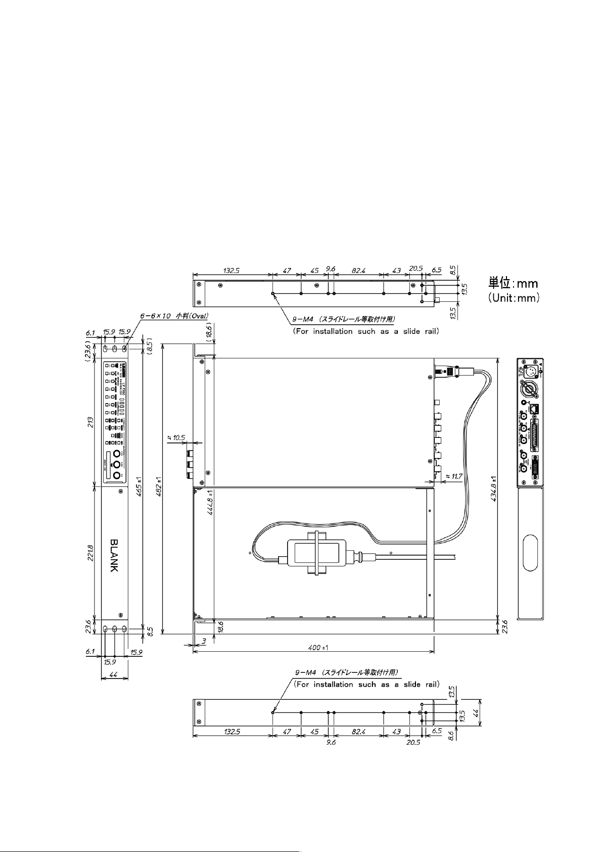
1.3 外形寸法図 Mounting Dimensions ........................................................................................ 2
2. 構成内容 Contents ................................................................................................... 3
3. 組み立て方法 .............................................................................................................. 4
3.1 取り外し部品 .......................................................................................................................... 4
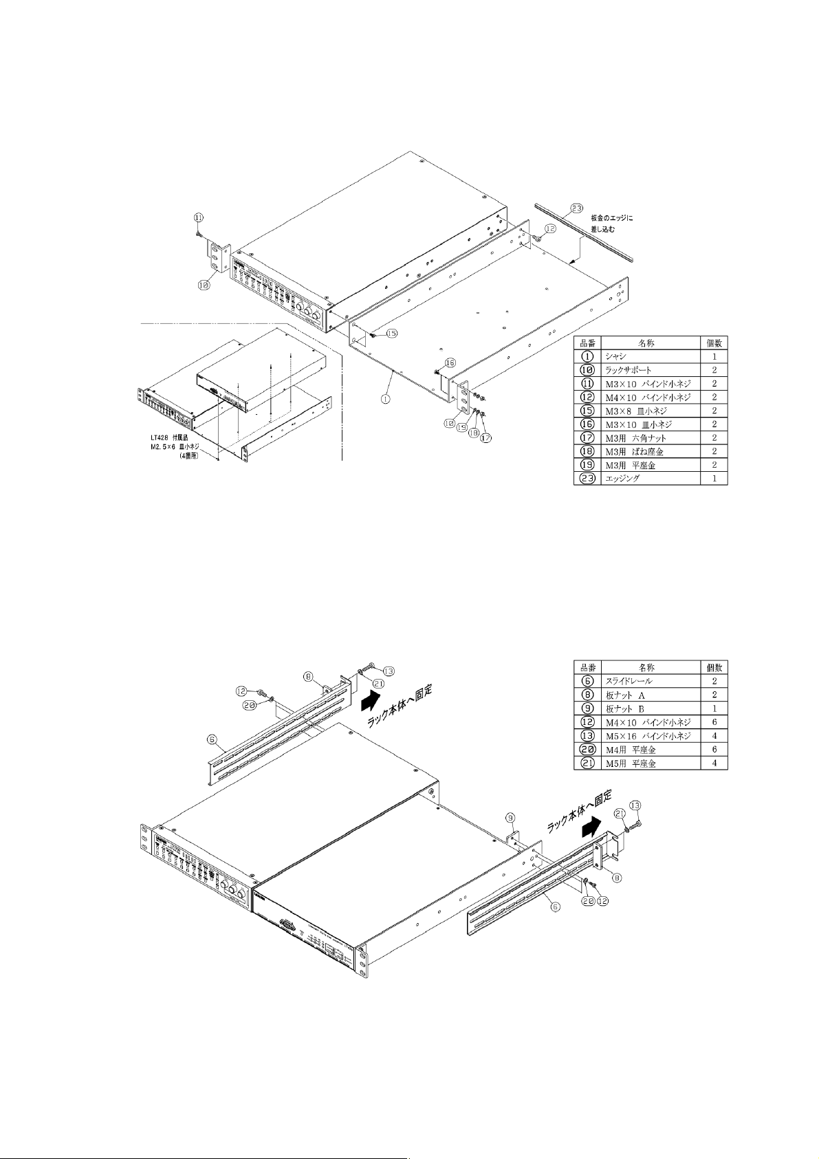
3.2 組み立て図.............................................................................................................................. 4
3.3 ACアダプタ固定方法 .............................................................................................................. 5
3.4 スライドレール固定方法 ........................................................................................................ 5
4. コンポーネントディジタルシンクジェネレータLT 428 の取り付け方法.................... 6
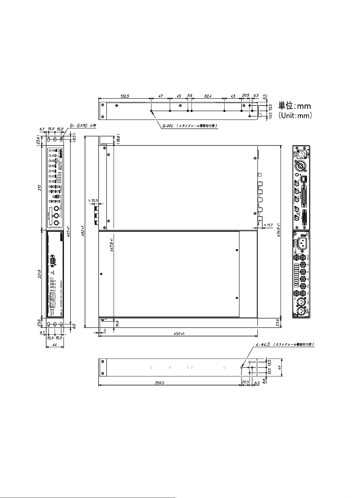
4.1 外形寸法図.............................................................................................................................. 6
4.2 組み立て図.............................................................................................................................. 7
4.3 スライドレール固定方法 ........................................................................................................ 7
5. Assembly Procedure .................................................................................................. 8
5.1 Parts to Be Removed.............................................................................................................. 8
5.2 Assembly Diagram.................................................................................................................. 8
5.3 Mounting AC Adapter .............................................................................................................. 9
5.4 Mounting Slide Rail ................................................................................................................. 9
6. Mounting the LT 428 Component Digital Sync Generator......................................... 10
6.1 Mounting Dimensions ........................................................................................................... 10
6.2 Assembly Diagram................................................................................................................ 11
6.3 Mounting Slide Rail ............................................................................................................... 11

製品を安全にご使用いただくために
GEN RY
を避けるためのものです。必ず下記の警告、注意事項を守ってご使用ください。
ie
and deteri
ERAL SAFETY SUMMA
下記に示す使用上の警告、注意事項は、使用者の身体、生命に対する危険および製品の損傷、劣化など
Rev w the following safety precautions to avoid operator’s injury and loss of life and prevent damage
oration to this instrument. To avoid potential hazards, use this product as specified.
■組み立てに関する注意事項 Warning Concerning Assembly
組み立ての際、板金のエッジ等でけがをするおそれがありますので、十分注意して組み立てて
■
ネジを使用すると製品本体に影響を及ぼし、火災、感電、故障、事故などの原因となります。
a
screw head. If the tightening torque is too low, the screws may come loose. If it is too tight, it may
1
呼
ください。
Exercise caution during assembly to prevent injury, such as from the edges of the metal plate.
使用ネジに関する警告事項 Warning Concerning the Screws
使用ネジは、組み立て図に従い指定の種類および長さのものを使用してください。指定以外の
Use screws of the specified type and length according to the assembly diagrams. Using other
screws may adversely affect the unit and can cause fire, electric shock, malfunction, accidents,
and so on.
■ ネジ締め付けトルクに関する警告事項
W rning Concerning the Screw Tightening Torque
ねじは頭の形に関わらず、表 1の締め付けトルクに従い締めてください。締めが弱いと緩みを
生じます。また、締め過ぎると破断やのびを生じ、いずれも故障の原因となります。
Fasten the screws according to the tightening torque of Table 1 regardless of the shape of the
lead to breaks or elongation and can cause a malfunction.
表(Table 1)
び径 Nominal Diameter 締め付けトルク Tightening Torque (N・cm)
M2.5 / M2.6 41.2
M3 59.8
M4 147.0
M5 294.0
1

1. 製品仕様
1.1 概要 De
LR 2480 はEIA(米国電子機械工業会)に準じた 19 インチラックに当社製品を取り付けるため
a 19-inch EIA
.2 対応機種 Applicable Models
LV 7700, LV 7720, LT 4400
1.3 外形寸法図 Mounting Dimensions
Specifications
scription
のラックマウントアダプタです。
The LR 2480 is a rack mount adapter used to attach Leader’s products to
(Electronic Industries Association) standard rack.
1
図1 (Figure 1)
2

2. 構成内容 Contents
LR 2480 は下記部品で構成されています。組み立て図に従い正しく組み立ててください。
The LR 2480 consists of the parts indicated below e parts correctly according to the
assembly diagrams.
品番 (No )
. Assemble th
.) 名称 (Item Name) 材質 (Material) 外装処理 (Finish) 個数 (Qty
1 ―― 1シャシ (Chassis) A5052P
2 パネル (Panel) A5052P 塗装 (Paint) 1
3 パネルサポート A (Panel Support A) SPCC クロメート (Zinc plating) 1
4 SPCC クロメート (Zinc plating) 1パネルサポート B (Panel Support B)
5 A5052P ―― 1リアパネル (Rear Panel)
6 スライドレール (Slide Rail) SPCC クロメート (Zinc plating) 2
7 AC アダプタサ
(AC Adapter Support)
SPCC ニッケル (Nickel plating) 1ポート
8 板ナット A (Plate Nut A) SPCC クロメート (Zinc plating) 2
9 板ナット B (Plate Nut B) SPCC クロメート (Zinc plating) 1
10 ラックサポート (Rack Support) A6063 塗装 (Paint) 2
11 M3×10 バインド小ネジ
(Binding head Screw)
鋼(Steel) ニッケル (Nickel plating) 8
12 M4×10 バインド小ネジ
(Binding head Screw)
鋼(Steel) ニッケル (Nickel plating) 10
13 M5×16 バインド小ネジ
(Binding head Screw)
鋼(Steel) ニッケル (Nickel plating) 4
14 M3×6 皿小ネジ (Flat head Screw) 鋼(Steel) 黒クロメート (Zinc plating) 2
15 M3×8 皿小ネジ (Flat head Screw) 鋼(Steel) ニッケル (Nickel plating) 8
16 M3×10 皿小ネジ (Flat head Screw) 鋼(Steel) ニッケル (Nickel plating) 2
17 M3用六角ナット (Hexagon Nut for M3) 鋼(Steel) ニッケル (Nickel plating) 2
18 M3用ばね座金
(Spring lock Washer for M3)
鋼(Steel) ニッケル (Nickel plating) 2
19 M3用平座金 (Plain Washer for M3) 鋼(Steel) ニッケル (Nickel plating) 2
20 M4用平座金 (Plain Washer for M4) 鋼(Steel) ニッケル (Nickel plating) 6
21 M5用平座金 (Plain Washer for M5) 鋼(Steel) ニッケル (Nickel plating) 4
22 エッジング (Edge protector) ナイロン (Nylon) ―― 1
23 タイベース (Tying base) ナイロン (Nylon) ―― 3
24 束線バンド A (Tying band A) ナイロン (Nylon) ―― 3
25 束線バンド B (Tying band B) ナイロン (Nylon) ―― 1
3

3. 組み立て方法
3.1 取り外し部品
図2に従い、LV 7700 の部品およびネジを取り外してください。
図2
3.2 組
図3
図3
み立て図
に従い組み立ててください。なお、左右どちら側にもマウントできます。
4

3.3 ACアダプタ固定方法
アダプタを固定してお使いになる際は、図 4に従い固定してください。ま
た、タイベースと束線バンド Aはケーブルの固定に利用してください。
3.4 スライドレール固定方法
図5に従いスライドレールを取り付けてください。なお、スライドレール固定位置はラック本
体の奥行きに合わせてください。
ラック本体への固定は、必ず前面および背面を固定してください。固定しない場合の事故につ
きましては責任を負いかねます。
図5
LV 7700 付属のAC
図4
5

4. コンポーネントディジタルシンクジェネレータLT 428 の取り付け方法
LR 2480 は当社製コンポーネントディジタルシンクジェネレータ LT 428 をマウントすることも
できます。下記の組み立て図に従い組み立ててください。
4.1 外形寸法図
図6
6

4.2 組み立て図
図7に従い組み立ててください。なお、左右どちら側にもマウントできます。
図7
.3 スライドレール固定方法
8取り付けてください。なお、スライドレール固定位置はラック本
よび背面を固定してください。固定しない場合の事故につ
図8
図 に従いスライドレールを
体の奥行きに合わせてください。
ラック本体への固定は、必ず前面お
きましては責任を負いかねます。
4
7

5. Assembly Procedure
5.1
igure 9.
Parts to Be Removed
Remove parts and screws from the LV 7700 according to F
Figure 9
5.2 Assembly Diagram
Assemble according to Figure 10. Furthermore, you can mount on either right or left side.
Figure 10
8

5.3 Mounting AC Adapter
the tying
base and tying band A to fix the cables in place.
Figure 11
5.4 Mounting Slide Rail
igure 12. Match the attachment positions of the slide rails to
ck at the front and back. Leader will not be help
responsible for accidents that occur when the slide rails are not fixed in place.
Figure 12
To fix the AC adapter that comes with the LV 7700 in place, follow Figure 11. Use
Attach the slide rails according to F
the depth of the rack.
Be sure to fix the slide rails to the ra
9

6. Mounting the LT 428 Component Digital Sync Generator
ed to mount the LT 428 Component Digital Sync Generator.
As .
6.1 Mounting Dimensions
The LR 2480 can also be us
semble the parts correctly according to the assembly diagram below
Figure 13
10

11
Figure 15
6.2 Assembly Diagram
Assemble according to Figure 14. Furthermore, you can mount on either right or left side.
Figure 14
6.3 Mounting Slide Rail
Attach the slide rails according to Figure 15. Match the attachment positions of the slide rails to
the depth of the rack.
Be sure to fix the slide rails to the rack at the front and back. Leader will not be help
responsible for accidents that occur when the slide rails are not fixed in place.

Following information is for Chinese RoHS only
LR 2480
此标志适用于在中国销售的电子信息产品,依据2006年2月28日公布的
《电子信息产品污染控制管理办法》以及SJ/T11364-2006《电子信息产品污染
控制标识要求》,表示该产品在使用完结后可再利用。数字表示的是环境保护使
用期限,只要遵守与本产品有关的安全和使用上的注意事项,从制造日算起在数
字所表示的年限内,产品不会产生环境污染和对人体、财产的影响。
产品适当使用后报废的方法请遵从电子信息产品的回收、再利用相关法令。
详细请咨询各级政府主管部门。
产品中有毒有害物质或元素的名称及含量
部件名称
有毒有害物质或元素 Hazardous Substances in each Part
Parts 铅 汞 镉 六价铬 多溴联苯 多溴二苯醚
(Pb) (Hg) (Cd) (Cr(Ⅵ)) (PBB) (PBDE)
主体部 × ○ ○ ○ ○ ○
附件 ○ ○ ○ ○ ○ ○
包装材 ○ ○ ○ ○ ○ ○
备注)
○:表示该有毒有害物质在该部件所有均质材料中的含量均在SJ/T11363-2006 规定的限量要求以下。
×:表示该有毒有害物质或元素至少在该部件的某一均质材料中的含量超出SJ/T11363-2006
标准规定的限量要求。
Ver.2
所
部件号码:
含有毒有害物质信息
Nov. 10, 2010 Ver.4
Table of contents
Languages:
Other Leader Adapter manuals
Popular Adapter manuals by other brands

Rolls
Rolls BT287 Connection guide

Black Box
Black Box USB Solo-E user guide

Linksys
Linksys PAP2 Installation and troubleshooting guide

Ruijie
Ruijie RG-AP620 Series installation guide

TRENDnet
TRENDnet TEW-664UB Quick installation guide

National Semiconductor
National Semiconductor SMA2RJ45EVK NOPB user guide