2.3. Assembling the case bottom (Bag C)
• Organise the parts and put everything in
place like on the rst picture 2.3-01
• The logo will later face to the front, the
power inlet and switch will face to the back.
• The side parts have a laser cut ring around
the holes, which faces outward later.
• Now insert the M5 screws to the
corresponding holes on the sides of the
rails to pre-cut the thread so it will be easier
to insert the screws later.
• Insert the Slide-Nut into the side of the rail,
then put the slider on top of it like seen on
the pictures.
• Now attach the rails to the sides using the
M3 screws and place the rails exactly in the
middle before xating. In one of the next
steps you will need the rails to hold the side
parts.
• Put everything in place that it looks like on
pics 2.3-01 and 2.3-12
• Apply glue like you did for the case top.
• Put it all together, rst front and back, then
the sides.
• In the next step you insert the M5 screws
into the pre-cut threads which should be
easy now. Do it tight but not too tight as this
will cause tension inside the long front and
back parts.
• Wipe off excess glue.
• Use clambs across the long and short
sides.
• Wipe off excess glue on the inside, then let
it dry for a couple of hours.
You have already seen the masking tape technique in chapter 2.1. The process is basically identical
for the case bottom but now we show you the more professional variant using clambs. Please don’t
use the clambs directly on the case, better is to use small wood-parts to transfer the pressure across
a larger area and less punctual. While using the clambs and also while xating the rails by the M5
screws please use enough pressure but not too much, as the long wood parts might bend towards
the middle then. Also here possibly do a dry run rst to make sure you understood the process.
2.4. Assembling the closing mechanism (Bag F)
• In the rst step you peel off half of the paper
from an adhesive felt-dot.
• Then insert a screw through the moddle
hole. This helps you to center the dot while
glueing on on the knob.
• Then put in on the at side of one of the 3D
printed knobs, make the shape align.
• Press and make it stick.
• Do the same with the other one.
• Insert the M3 savety nuts with the at side
facing down and push them down into the
hole.
• Put the knobs on the case from the outside
and xate it with the screw from the inside.
• The screw should sit so far into the sacety
nut that its end sticks in the nylon ring. That
makes sure it doesn’t fall off when used a
lot.
• It should sit tight but should be easily
possible to turn the knob.
• Now you should be able to open and close
your case.
Knappla
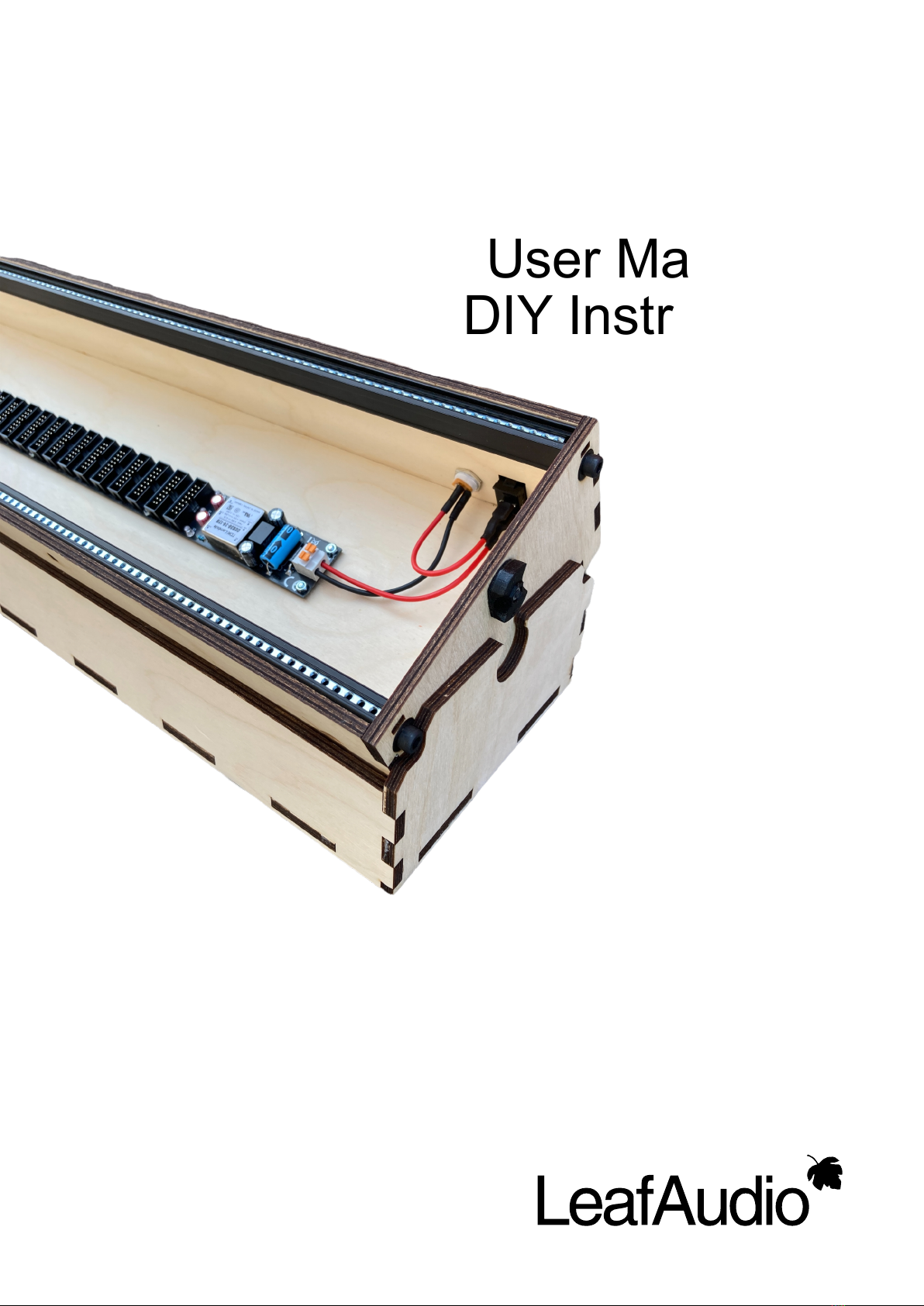
da
User Manual & DIY Instructions