LEGRAND MINKELS CW40 User manual

1
HF61G00113C HRCC-0-UM-GB
GB
User Manual
CW40-CW60
Close Control Chilled-Water Unit for high density systems
Rev. 26/08/2021
Rev. 01/07/2021
HF61G00679B CW MINKELS-0-UM-GB_HIREF
HF61G00679A HRCC MINKELS-0-UM-GB_HIREF

HF61G00113D HRCC-0-UM-GB
HF61G00683B NRCD MINKELS-0-UM-GB_HIREF

3
HF61G00113D HRCC-0-UM-GB
HF61G00683B NRCD MINKELS-0-UM-GB_HIREF
Index
1General Description ........................................................................................................................1
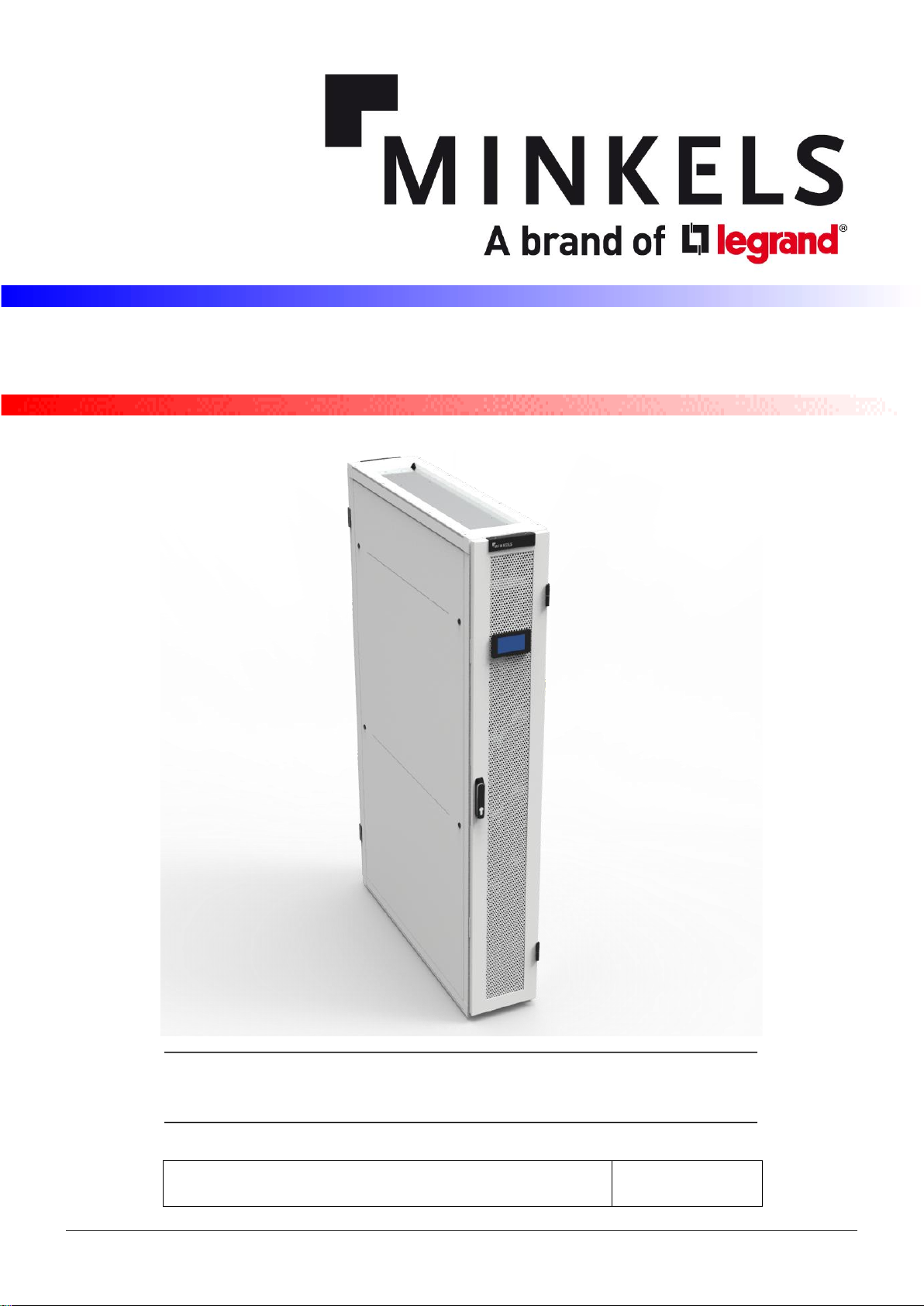
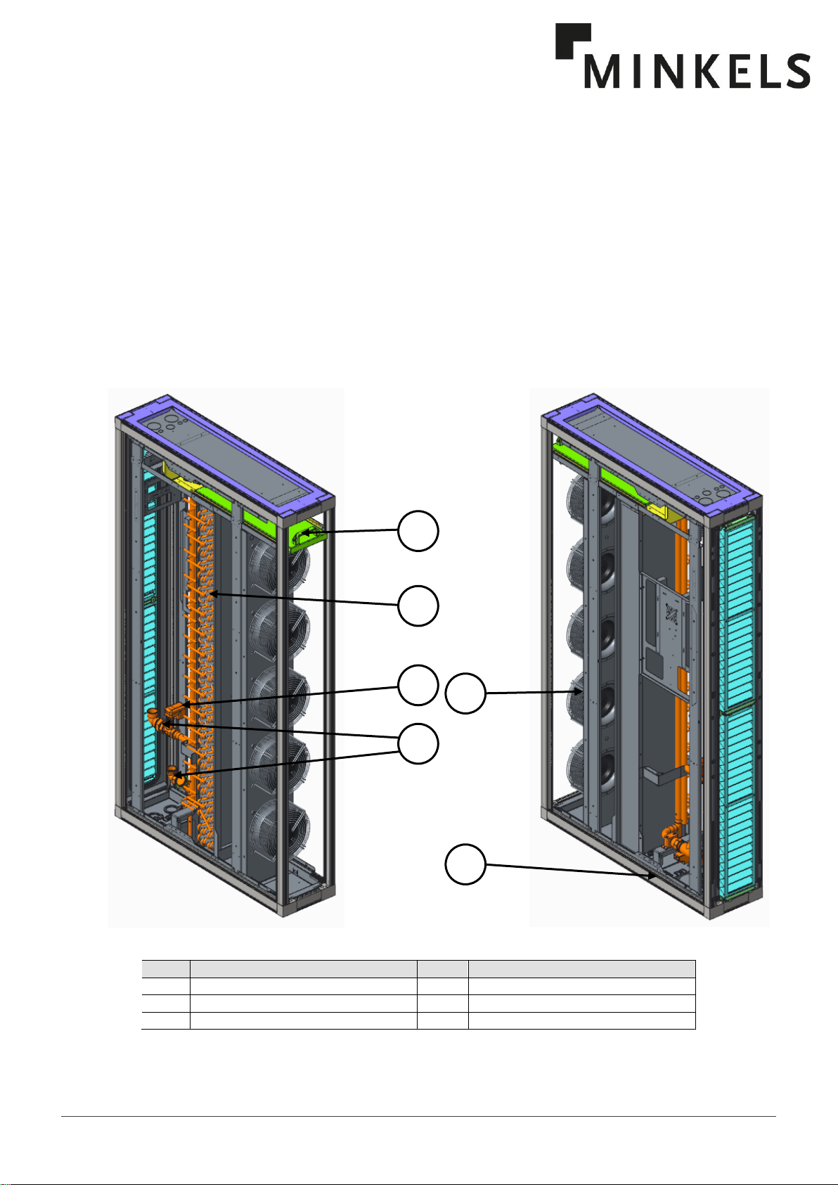
1.1 Structure....................................................................................................................................................................2
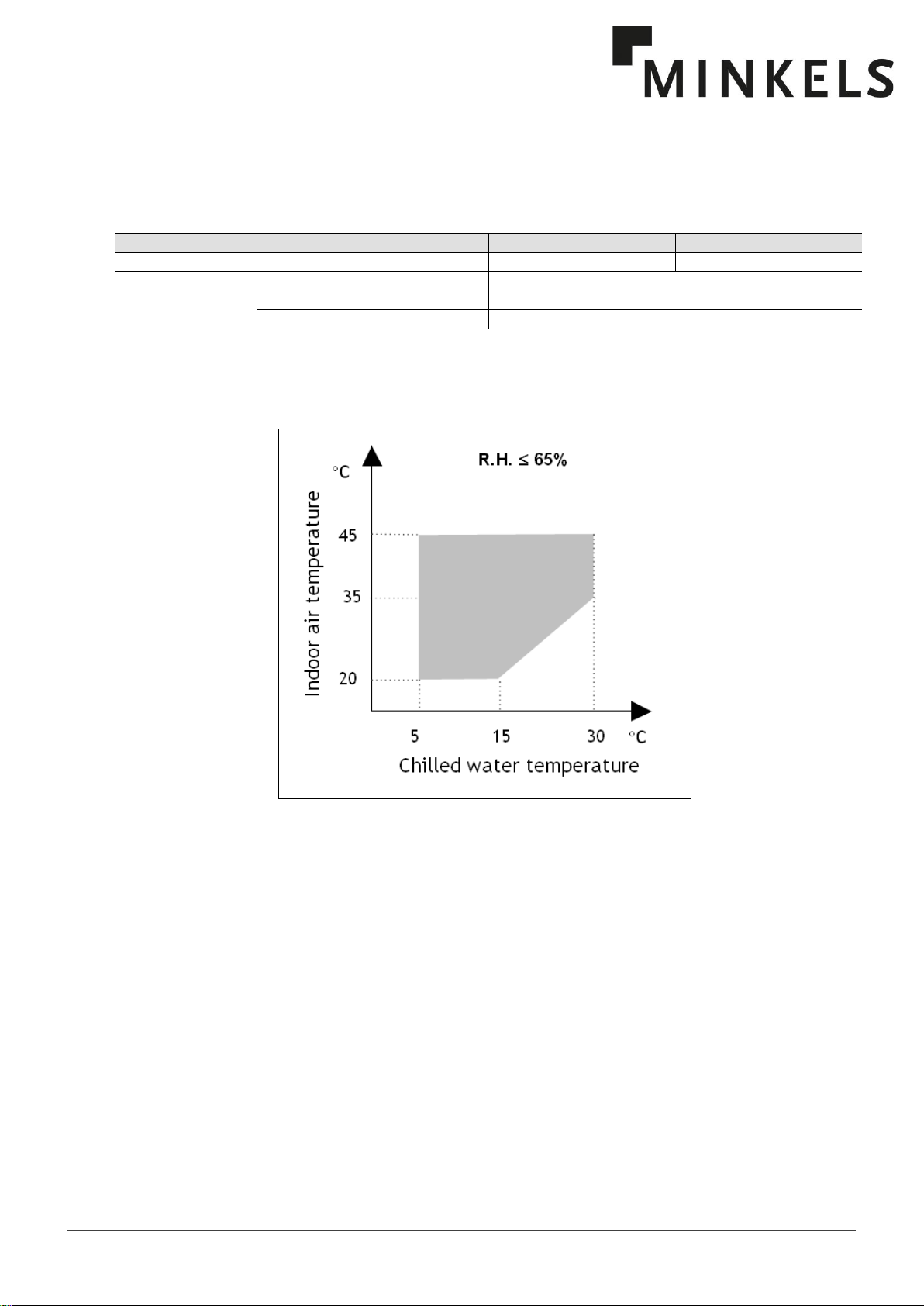
1.2 Application limits .......................................................................................................................................................3
1.3 Components..............................................................................................................................................................3
1.4 Installation warnings..................................................................................................................................................5
2Inspection / Transport / Positioning...............................................................................................6
2.1 Inspection on receipt.................................................................................................................................................6
2.2 Lifting and transport ..................................................................................................................................................6
2.3 Unpacking .................................................................................................................................................................6
2.4 Positioning.................................................................................................................................................................6
3Installation.......................................................................................................................................7
4Electrical Connections....................................................................................................................8
4.1 Generalities...............................................................................................................................................................8
5Operating Diagrams......................................................................................................................10
6Start-Up..........................................................................................................................................11
6.1 Preliminary checks..................................................................................................................................................11
6.2 Starting operations..................................................................................................................................................11
7Setting Operating Parameters......................................................................................................12
7.1 Generalities.............................................................................................................................................................12
8Maintenance ..................................................................................................................................13
8.1 Warnings.................................................................................................................................................................13
8.2 Generalities.............................................................................................................................................................13
9Troubleshooting............................................................................................................................15

HF61G00113D HRCC-0-UM-GB
HF61G00683B NRCD MINKELS-0-UM-GB_HIREF

1
HF61G00113D HRCC-0-UM-GB
HF61G00683B NRCD MINKELS-0-UM-GB_HIREF
1
1 General Description
CW40-CW60 “CCAC” self-contained units are specially designed for installation in technological
environments where a spot cooling is needed . CW40-CW60 units represent the state of the art between
technology and design as well as all HiRef S.p.A. products: The depth of 1200 mm, allows the compatibility
with standard server rack: furthermore the innovative design and the high tech selected colours make CW40-
CW60 units complementary to the last generation of IT devices. The internal design of the units in firstly made
looking to efficiency and reliability but don’t loosing accessibility: all components, including fans, valves,
electrical components, etc. can be maintained from the front . The exclusive use of primary brands
components and a fully integrated development process (CAD + CAM, CAE) stands for highest possible quality
level regarding efficiency, reliability, maintenance time, pre and after sales support.
CW40
Pos.
Description
Pos.
Description
1
Chilled water coil
4
Radial Fan
2
Electrical panel
5
Water valve
3
Stainless steel drain pan
6
Water connections
2
3
4
1
6
5

HF61G00113D HRCC-0-UM-GB
HF61G00683A NRCD MINKELS-0-UM-GB_HIREF
2
CW 60
Pos.
Description
Pos.
Description
1
Chilled water coil
4
Radial Fan
2
Electrical panel
5
Water valve
3
Stainless steel drain pan
6
Water connections
1.1 Structure
CW40-CW60 units are designed with a self supporting frame and all components are produced using
sophisticated computer driven machines and special tools. All sheet metals are galvanized powder coated
giving to the units the image and the quality like last generation of IT devices. All fixing elements are made in
stainless steel or in non corroding materials. The drain pan is made in stainless steel in order to ensure long
time operation without damages.

3
HF61G00113D HRCC-0-UM-GB
HF61G00683B NRCD MINKELS-0-UM-GB_HIREF
3
1.2 Application limits
Tab. 2 Operation limits
Power supply limits and storage conditions
Model
CW40
CW60
Power supply
[Vac / Ph / Hz]
230 (±10%) / 1 / 50-60
400 (±10%) / 3+N / 50
Storage conditions
Temperature
from
-10 °C
to
+50 °C
Relative humidity
less than
90 %
Fig. 2 Application limits
1.3 Components
Electric control board
Electric control board: The electric control board is constructed and wired in accordance with Directives
73/23/EEC and 89/336/EEC and related standards. The board may be accessed through a door after the
main switch has been turned off.
All the remote controls use 24 V signals powered by a safety transformer situated in the electrical panel.
Microprocessor control
The microprocessor built into the unit allows the different operating parameters to be controlled from a set of
pushbuttons situated on the control panel on the door.
- Water valve modulation to maintain the temperature set point
- Alarm management : - High / Low temperature;
- Dirty filters alarm (optional);
- Air flow alarm.
- Alarm signalling.
- Display of operating parameters.
See the Software Manual for further details.

HF61G00113D HRCC-0-UM-GB
HF61G00683A NRCD MINKELS-0-UM-GB_HIREF
4
Fig.1 Basic cooling circuit
Pos.
Description
Pos.
Description
1
Chilled water inlet
5
Coil heat exchanger
2
Chilled water outlet
6
Breather valve
3
3-way valve (Opt.)
7
2-way valve
4
Plug fan
-
Water Valve
Modulating valves allow an high precision in controling the rack temperature
-3 way for constant flow systems
-2 way valve for variable flow. In this case Free cooling application range will be extended thanks to the
increase of return water T once the load decreases.
Valves’ technical data:
Model
CW40
CW60
Brand / valve’s type
Danfoss / VRG
Danfoss / VRG
PN valve
16
16
Dimension (inch)
1 1/2"
2 1/4"
2-way valve
3-way valve
Actuator

5
HF61G00113D HRCC-0-UM-GB
HF61G00683B NRCD MINKELS-0-UM-GB_HIREF
5
All CW units are supplied with 3 or 2 way valve with 0 ÷ 10 V signal regulation.
1.4 Installation warnings
General rules
- When installing or servicing the unit, you must strictly follow the rules provided in this manual, comply with the
directions on the units themselves and take all such precautions as are necessary.
- The fluids under pressure in the cooling circuit and the presence of electrical components may cause hazardous
situations during installation and maintenance work.
All work on the unit must be carried out by qualified personnel only, trained to do their job
in accordance with current laws and regulations.
- Failure to comply with the rules provided in this manual or any modification made to the unit without prior
authorisation will result in the immediate invalidation of the warranty.
Warning: Before performing any kind of work on the unit, make sure it has been
disconnected from the power supply.

HF61G00113D HRCC-0-UM-GB
HF61G00683A NRCD MINKELS-0-UM-GB_HIREF
6
2 Inspection / Transport / Positioning
2.1 Inspection on receipt
On receiving the unit, check that it is perfectly intact: the unit left the factory in perfect conditions; immediately
report any signs of damage to the carrier and note them on the “Delivery Slip” before signing it.
Minkels or its agent must be promptly notified of the entity of the damage. The Customer must submit a written
report describing every significant sign of damage.
2.2 Lifting and transport
While the unit is being unloaded and positioned, utmost care must be taken to avoid abrupt or violent
manoeuvres. The unit must be handled carefully and gently; avoid using machine components as anchorages
or holds and always keep it in an upright position.
The unit should be lifted using the pallet it is packed on; a transpallet or similar conveyance means should be used.
Warning: In all lifting operations make sure that the unit is securely anchored in order to prevent
accidental falling or overturning.
2.3 Unpacking
The packing must be carefully removed to avoid the risk of damaging the unit. Different packing materials are
used: wood, cardboard, nylon etc. It is recommended to keep them separately and deliver them to suitable
waste disposal or recycling facilities in order to minimise their environmental impact.
2.4 Positioning
Bear in mind the following aspects when choosing the best site for installing the unit and the relative connections:
-positioning and dimensions of the coupling flanges;
- location of power supply;
- solidity of the supporting floor.
It is recommended to first prepare the floor/wall for passing through the power cables.
The dimensions of the air outlet and the positions of the holes for the screw anchors and power cables are
shown in the dimensional drawing (see the documentations delivered together with the unit)

7
HF61G00113D HRCC-0-UM-GB
HF61G00683B NRCD MINKELS-0-UM-GB_HIREF
7
3 Installation
The CW40-CW60 air-conditioning unit is suitable for all environments except aggressive ones. Do not place
any obstacles near the units and make sure that the air flow is not impeded by obstacles and/or situations
causing back suction.
Fig. 7 Service area
For the option to exchange the entire unit, a space of 1400mm is required on one side.
The following steps should be carried out to ensure proper installation:
- Position the unit on the floor and adjust with the levelling feet to align with the adjacent racks.

HF61G00113D HRCC-0-UM-GB
HF61G00683A NRCD MINKELS-0-UM-GB_HIREF
8
4 Electrical Connections
4.1 Generalities
Before carrying out any job on electrical parts, make sure the power supply is
disconnected.
Check that the mains electricity supply is compatible with the specifications (voltage, number of phases,
frequency) shown on the unit rating plate.
The size of the cable and line protections must conform to the specifications provided in
the wiring diagram.
The supply voltage may not undergo fluctuations exceeding ±10% of the rated values indicated on the
nameplate
The above operating conditions must always be complied with: failure to ensure said
conditions will result in the immediate invalidation of the warranty.
The electrical connections must be made in accordance with the information shown in the wiring diagram
provided with the unit and with current and local regulations. An earth connection is mandatory. The installer
must connect the earthing wire using the earthing terminal (yellow and green wire) situated on the electric
control board (CW60 unit) or in the mains inlet at the back side (CW40 unit). The power supply to the control
circuit is taken from the power line through an insulating transformer situated on the electric control board. The
control circuit is protected by suitable fuses or automatic breakers depending on the unit size.
The recommended sizes for the power cables are shown in the electrical diagram attached on the unit
documentation.
When the motor runs independently due to air flowing through or if it continues to
run down after being turned off, dangerous voltages of over 50V can arise on the
motor internal connections through operation of the generator.
Even after disconnecting the mains voltage, life-threating charges can appear
between the protective ground “PE” and the mains connection. The protective earth
is conducting high discharge currents (dependent on the switching frequency, current
source voltage and motor capacity). Earthing in compliance with EN specifications
shall therefore be observed even for testing and trial conditions (EN 50 178,
Art.5.2.11).

9
HF61G00113D HRCC-0-UM-GB
HF61G00683B NRCD MINKELS-0-UM-GB_HIREF
9
Regarding the differential protection that needs to be installed upstream, it is necessary to use a type A switch
that is sensitive to direct currents. It is mandatory for it to have the following features:
1. Calibratable operation threshold 300mA
2. Calibratable operation delay 200ms

HF61G00113D HRCC-0-UM-GB
HF61G00683A NRCD MINKELS-0-UM-GB_HIREF
10
5 Operating Diagrams
Changing the side, frontal and rear pannels it’s possible to modify the air flow configuration of the CW40 as in
the following pictures. On the CW60 only “Horizontal Air Flow (Rear-Front) configuration is possible.
Fig. 11 Operating diagrams

11
HF61G00113D HRCC-0-UM-GB
HF61G00683B NRCD MINKELS-0-UM-GB_HIREF
11
6 Start-Up
6.1 Preliminary checks
Check that the electrical connections have been made properly and that all the terminals are securely
tightened.
This check should also be included in a periodic one year inspection.
6.2 Starting operations
Before starting the unit, turn the main switch on, select the operating mode desired from the control panel and
press the ”ON” button on the control panel.
If the unit fails to start up, check if the service thermostat has been set according to the nominal values
provided.
You should not disconnect the unit from the power supply during periods when it is
inoperative but only when it is to be taken out of service for a prolonged period (e.g. at the
end of the season).
Never attempt to modify internal electrical connections: any undue modifications will
immediately invalidate the warranty.

HF61G00113D HRCC-0-UM-GB
HF61G00683A NRCD MINKELS-0-UM-GB_HIREF
12
7 Setting Operating Parameters
7.1 Generalities
All the control devices are set and tested in the factory before the unit is dispatched. However, after the unit
has been in service for a reasonable period of time you can perform a check on the control devices. The
settings are shown in Tab. 5.
All servicing of the equipment is to be considered extraordinary maintenance and may be
carried out BY QUALIFIED TECHNICIANS ONLY: incorrect settings may cause serious
damage to the unit and injuries to persons.
The operating parameters and control system settings configurable by means of the microprocessor control
are password protected if they have a potential impact on the integrity of the unit.
Tab. 5 Setting of control devices
Control device
Set point
Differential
Differential air pressure switch (dirty filter)
Pa
350
20
Values to be calibrated depending on the application.

13
HF61G00113D HRCC-0-UM-GB
HF61G00683B NRCD MINKELS-0-UM-GB_HIREF
13
8 Maintenance
The only operations to be performed by the user are to switch the unit on and off. All other operations are to
be considered maintenance work and must thus be carried out by qualified personnel trained to do their job in
accordance with current laws and regulations.
8.1 Warnings
All the operations described in this chapter MUST ALWAYS BE PERFORMED BY QUALIFIED
PERSONNEL ONLY.
Before carrying out any work on the unit or accessing internal parts, make sure you have
disconnected it from the mains electricity supply.
Be especially careful when working in proximity to finned coils since the 0.11 mm-thick
aluminium fins can cause superficial injuries due to cuts.
After completing maintenance jobs, always replace the panels enclosing the units and secure
them with the fastening screws provided.
8.2 Generalities
To guarantee a constantly satisfactory performance over time, it is advisable to carry out routine maintenance
and checks as described below. The indications are related to standard tear and wear.
Tab. 7 Routine maintenance
Operation
Frequency
Check the efficiency of all the control and safety devices.
Once a year
Check the terminals on the electric control board to ensure that they are securely tightened. The movable and
fixed contacts of the circuit breakers must be periodically cleaned and replaced whenever they show signs of
deterioration.
Once a year
Check the efficiency of the dirty filter differential pressure switch.
Every 6 months
Check the condition of the air filter and replace it if necessary.
Every 6 months

HF61G00113D HRCC-0-UM-GB
HF61G00683A NRCD MINKELS-0-UM-GB_HIREF
14
Fig. 15 Purging the air out of the water coil
The relief valve is accessible from the backside of the unit
CW40
CW60

15
HF61G00113D HRCC-0-UM-GB
HF61G00683B NRCD MINKELS-0-UM-GB_HIREF
15
9 Troubleshooting
On the next pages you will find a list of the most common reasons that may cause the package unit to fail or
any malfunction. These causes are broken down according to easily identifiable symptoms.
You should be extremely careful when attempting to implement any of the possible remedies
suggested: overconfidence can result in injuries, even serious ones, to inexpert individuals.
Therefore, once the cause has been identified, you are advised to contact the manufacturer
or a qualified technician for help.
Tab. 9 Fault - Causes - Corrections
FAULT
POSSIBLE CAUSES
CORRECTIVE ACTIONS
The unit does not
start
No power supply.
Check if power is being supplied both to the primary and auxiliary
circuits.
The electronic card is cut off from the power
supply.
Check the fuses.
Alarms have been released.
Check whether any alarms are signalled on the microprocessor
control panel, eliminate the causes and restart the unit.
Air in the
hydraulic circuit
During external connections.
Drain the air using the relief valves (see Fig.15)
Water out from the
unit
The drain pan hole is closed.
Open the front panels, remove the sheet metal just below the e-
panel (down flow units) and clean it.
The siphon is missing.
Check for the presence and provide for a new one.
The air flow is too high.
Reduce the fan speed up to reaching the nominal air flow.

HF61G00113D HRCC-0-UM-GB
HF61G00683A NRCD MINKELS-0-UM-GB_HIREF
16
This manual suits for next models
1
Table of contents
Popular Chiller manuals by other brands

MAXA
MAXA HMV-A Series Technical manual

Polar Electro
Polar Electro UA014 instruction manual

Williams
Williams WBC10 OPERATING & ENGINEERS MANUAL

Cornelius
Cornelius CH 551 Operator's & installation manual

York
York Millennium YCAS0130EC manual

Lennox
Lennox ECOLEAN EAC Series Installation, operating and maintenance

Trane
Trane 2TTZ9C Installer's guide

SMC Networks
SMC Networks HRW D Series Operation manual

Glastender
Glastender MF24 Series Operation manual

System air
System air SyScrew Water EVO CO Series Installation and maintenance manual

Water Furnace
Water Furnace TruClimate 300 installation manual

Glastender
Glastender MFV24 Operation manual