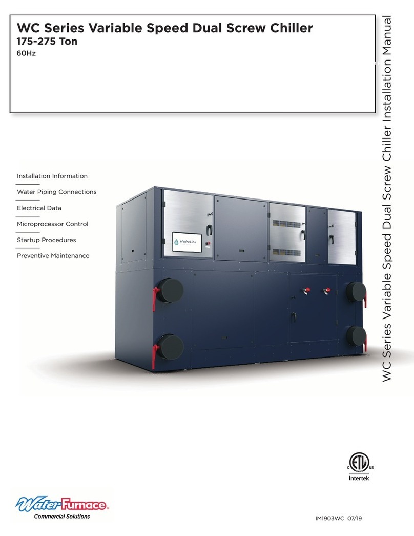
Water Furnace TruClimate 700 User manual

IM1904WW 05/23
Installation Information
Water Piping Connections
Electrical Data
Microprocessor Control
Startup Procedures
Preventive Maintenance
TruClimate 700 90-140 Ton Installation Manual
I ll i Ml
Commercial 60 Hz
Water-Cooled Chiller
• R-513A Refrigerant
• 90-140 Ton Lead Variable Speed Compressor
In
st
alla
ti
on
I
nf
or
ma
ti
on
W
ater P
i
p
i
ng Connect
i
on
s
El
ectrica
l
Dat
a
M
icr
op
rocessor Contro
l
Startup Proce
d
ures
Pr
ev
en
ti
ve
M
ai
nt
en
an
ce
TruC
l
imate 700 90-140


TRUCLIMATE 700 90-140 TON INSTALLATION MANUAL
Table of Contents
General Installation Information . . . . . . . . . . . . . . . . . . . . . . . . . . . . . . . . . . . . . . . . . . . . . . . . . . . . 4
Model Nomenclature . . . . . . . . . . . . . . . . . . . . . . . . . . . . . . . . . . . . . . . . . . . . . . . . . . . . . . . . . . . . . . 5
Electrical Availability . . . . . . . . . . . . . . . . . . . . . . . . . . . . . . . . . . . . . . . . . . . . . . . . . . . . . . . . . . . . . . 5
HydroLink Supervisory Control Nomenclature. . . . . . . . . . . . . . . . . . . . . . . . . . . . . . . . . . . . . . . . 6
TruClimate 700 Features. . . . . . . . . . . . . . . . . . . . . . . . . . . . . . . . . . . . . . . . . . . . . . . . . . . . . . . . . . . 7
Dimensional Data . . . . . . . . . . . . . . . . . . . . . . . . . . . . . . . . . . . . . . . . . . . . . . . . . . . . . . . . . . . . . . . . 10
Chiller Installation . . . . . . . . . . . . . . . . . . . . . . . . . . . . . . . . . . . . . . . . . . . . . . . . . . . . . . . . . . . . . . . . 14
Removing a Module from the Bank of Units . . . . . . . . . . . . . . . . . . . . . . . . . . . . . . . . . . . . . . . . . 18
Lifting and Short Distance Transport . . . . . . . . . . . . . . . . . . . . . . . . . . . . . . . . . . . . . . . . . . . . . . . 19
Water Quality . . . . . . . . . . . . . . . . . . . . . . . . . . . . . . . . . . . . . . . . . . . . . . . . . . . . . . . . . . . . . . . . . . .20
Water Connections. . . . . . . . . . . . . . . . . . . . . . . . . . . . . . . . . . . . . . . . . . . . . . . . . . . . . . . . . . . . . . . 22
Operating Limits . . . . . . . . . . . . . . . . . . . . . . . . . . . . . . . . . . . . . . . . . . . . . . . . . . . . . . . . . . . . . . . . . 22
Electrical Data . . . . . . . . . . . . . . . . . . . . . . . . . . . . . . . . . . . . . . . . . . . . . . . . . . . . . . . . . . . . . . . . . . . 23
Electrical Connections. . . . . . . . . . . . . . . . . . . . . . . . . . . . . . . . . . . . . . . . . . . . . . . . . . . . . . . . . . . . 23
Electrical System and Controls - Safety Circuit . . . . . . . . . . . . . . . . . . . . . . . . . . . . . . . . . . . . . . 24
Wiring Schematics . . . . . . . . . . . . . . . . . . . . . . . . . . . . . . . . . . . . . . . . . . . . . . . . . . . . . . . . . . . . . . . 26
HydroLink2 Aurora Chiller Controls . . . . . . . . . . . . . . . . . . . . . . . . . . . . . . . . . . . . . . . . . . . . . . . . 28
Controls and BAS Integration . . . . . . . . . . . . . . . . . . . . . . . . . . . . . . . . . . . . . . . . . . . . . . . . . . . . . 35
Evaporator Pressure Drop. . . . . . . . . . . . . . . . . . . . . . . . . . . . . . . . . . . . . . . . . . . . . . . . . . . . . . . . . 36
Condenser Pressure Drop . . . . . . . . . . . . . . . . . . . . . . . . . . . . . . . . . . . . . . . . . . . . . . . . . . . . . . . . . 37
Start-Up Data Collection. . . . . . . . . . . . . . . . . . . . . . . . . . . . . . . . . . . . . . . . . . . . . . . . . . . . . . . . . . 38
Screw Refrigeration Cycle Analysis . . . . . . . . . . . . . . . . . . . . . . . . . . . . . . . . . . . . . . . . . . . . . . . . 39
Reference Calculations, Legend, and Unit Startup . . . . . . . . . . . . . . . . . . . . . . . . . . . . . . . . . . .40
Preventative Maintenance. . . . . . . . . . . . . . . . . . . . . . . . . . . . . . . . . . . . . . . . . . . . . . . . . . . . . . . . . 41
Troubleshooting . . . . . . . . . . . . . . . . . . . . . . . . . . . . . . . . . . . . . . . . . . . . . . . . . . . . . . . . . . . . . . . . . 42
Chiller Start-up Report . . . . . . . . . . . . . . . . . . . . . . . . . . . . . . . . . . . . . . . . . . . . . . . . . . . . . . . . . . . 43
Revision Guide. . . . . . . . . . . . . . . . . . . . . . . . . . . . . . . . . . . . . . . . . . . . . . . . . . . . . . . . . . . . . . . . . . . 47

4
TRUCLIMATE 700 90-140 TON INSTALLATION MANUAL
Safety Considerations
This appliance is not intended for use by persons
(including children) with reduced physical, sensory,
or mental capabilities, or lack of experience and
knowledge, unless they have been given supervi-
sion or instruction concerning use of the appliance
by a person responsible for their safety.
Children should be supervised to ensure that they
do not play with the appliance.
Maximum altitude for this equipment shall not
exceed 2000 m.
For installation only in locations not accessible to
the general public.
Installing and servicing air conditioning and
heating equipment can be hazardous due to system
pressure and electrical components. Only trained and
qualified service personnel should install, repair or service
heating and air conditioning equipment. When working
on heating and air conditioning equipment, observe
precautions in the literature, tags and labels attached to the
unit and other safety precautions that may apply.
Follow all safety codes. Wear safety glasses and work
gloves. Use quenching cloth for brazing operations. Have
fire extinguisher available for all brazing operations.
NOTE: Before installing, check voltage of unit(s) to ensure
proper voltage.
WARNING: Before performing service or
maintenance operations on the system, turn off
main power switches to the unit. Electrical shock
could cause serious personal injury.
Application
Units are not intended for heating domestic (potable water)
by direct coupling. If used for this type of application, a
secondary heat exchanger must be used.
Moving and Storage
Move units in the normal “Up” orientation as indicated by
the labels on the unit packaging. When the equipment
is received, all items should be carefully checked against
the bill of lading to ensure that all crates and cartons
have been received in good condition. Examine units for
shipping damage, removing unit packaging if necessary
to properly inspect unit. Units in question should also
be internally inspected. If any damage is observed, the
carrier should make the proper notation on delivery receipt
General Installation Information
acknowledging the damage. Units are to be stored in a
location that provides adequate protection from dirt, debris
and moisture.
Units are setup to be side picked using a fork lift. Some
units include pick bars allowing for picking from the end
with required fork lengths. Note unit labels and markings
for safe picking points. Do not pick the unit up from points
not specified and keep the unit level during transport and
handling. Using improper equipment handling methods can
result in damage and/or void the warranty.
WARNING: To avoid equipment damage, do not
leave the system filled in a building without heat
during cold weather, unless adequate freeze
protection levels of antifreeze are used. Heat
exchangers do not fully drain and will freeze
unless protected, causing permanent damage.
Unit Location
Provide sufficient room to make water and electrical
connections. If the unit is located in a confined space,
provisions must be made for unit servicing. Locate the
unit in an indoor area that allows easy removal of the
access panels and has enough space for service personnel
to perform maintenance or repair. These units are not
approved for outdoor installation and, therefore, must be
installed inside the structure being conditioned. Do not
locate units in areas subject to freezing conditions.
WARNING: Do not store or install units in
corrosive environments or in locations subject
to temperature or humidity extremes. Corrosive
conditions and high temperature or humidity can
significantly reduce performance, reliability, and
service life.
WARNING: To avoid equipment damage and
possible voiding of warranty, be sure that properly
sized strainers are installed upstream of both
brazed plate heat exchangers to protect them
against particles in the fluid.

5
TRUCLIMATE 700 90-140 TON INSTALLATION MANUAL
Model Nomenclature - TruClimate 700
All TruClimate 700 90-140 Ton product is Safety listed under UL1995 thru ETL
WCH S M G 140 * 4
2-3 5 7-9 11 12 13
Brand
W - WaterFurnace
Model Type
CH – Heat Recovery Chiller
Compressor Type
S – Variable Speed Single
Screw
Cabinet Configuration
M – Modular
Refrigerant Type
G – R-513A
Unit Capacity (Nominal Tons)
140,115,090
Vintage
* – Factory Use Only
Voltage
4 – 460/60/3
Electrical Option
A – Fused Disconnect
Control Option
D – Primary Unit (Master
Controller)
Non-Standard Options
SSS – None
Future Option
N – Not Applicable
Future Option
0 – Not Applicable
Future Option
0 – Not Applicable
Future Option
0 – Not Applicable
Water Control Option
8GC – Grooved 8in Integrated 4
Pipe
Future Option
0 – Not Applicable
Refrigeration Option
3 – EEV
Cabinet Option
S – Standard
Sound Kit Option
B – Cabinet Sound
14 16
15 17 18-20 21 22 23 24 25-271014
A D B S 3 0 8GC 0 0 0 N
WCHSMG140*4ADBS308GC000NSSS
SSS
6
Electrical Availability
Voltage Dual Variable Speed
208-230/60/3
460/60/3 ●●●
575/60/3
3/16/23

6
TRUCLIMATE 700 90-140 TON INSTALLATION MANUAL
HydroLink Supervisory Control Nomenclature (Accessory)
HSC D A 1 C F SS
456789-10
B
111-3
Vintage
B –Current
Non-Standard Option
Details
SS –Standard Option
Future
F –Future
Number of Modules
A –2modules
B –3modules
C –4modules
D –5modules
Family
HSC –HydroLink Supervisory Control
Chiller Module
N –NXW –Compact Scroll
D –WC –Dual Scroll Modular Chiller
S –WCHVE –VS Dual Screw Chiller
Header Rack
A –No Header Rack
B –4Pipe Standard (Dedicated Chiller)
C –4Pipe Reversing (Dedicated Chiller)
D –6Pipe Dedicated (Reversible Chiller)
E –6Pipe Standard (Dedicated Chiller)
F –4Pipe Standard (Reversible Chiller)
Hydrolink2 Control
1 – Standard –BACNet
2 – LonWorks

7
TRUCLIMATE 700 90-140 TON INSTALLATION MANUAL
The TruClimate 700 Features
Standard Aurora Hydrolink microprocessor
controls include set-point control, advanced
refrigeration monitoring, a standard color
touch-screen interface, advanced trending
and diagnostics, and standard provisions for
remote access using BACnet
Color touch screen chiller interface
provides easy-to-use instant access
to unit performance
Low impedance line reactors
reduce harmonic noise and
improve power factor
Remote HydroLink Supervisory
Controller (optional) enables staging
multiple units and can accommodate
additional controls, flow meters,
pump control, power analyzers, and
additional sensors.
Fused power supply for high
short circuit current rating

8
TRUCLIMATE 700 90-140 TON INSTALLATION MANUAL
The TruClimate 700 Features cont.
Factory installed
flow switches
and modulating
isolation valves
Variable speed drive
integrated with
compressor provides
envelope control for
improved reliability
DC Inverted Variable
Speed Single Screw
Compressor
Removable 4-pipe
header rack
Full enclosure foam
lined panels for sound
attenuation
Fork pockets and lifting
points in the frame enable
maneuverability for
installation and shipment
8 [in.] Grooved SCH40
Steel Pipe

9
TRUCLIMATE 700 90-140 TON INSTALLATION MANUAL
The TruClimate 700 Features cont.
The True "Modular" Concept
Header rack
installation
possible thread
of chiller module
installation
Forklift pockets
for easy refrigeration module
installation and removal
Most modular chillers can be ganged together but once in place cannot be easily serviced or removed. WaterFurnace
modular screw units feature several industry firsts to provide a true modular chiller!
1. Modular chiller unit can be removed from the bank and replaced with a new unit using strategically placed fork truck
pockets.
2. Majority of servicing can be accomplished from front (control box) of unit. Zero service clearance on side. Top panels
are removable with unit in place.
3. Chiller section can be separated from the pipe rack for service or replacement with pipe rack remaining plumbed and
intact due to the isolation valves at the pipe rack.

10
TRUCLIMATE 700 90-140 TON INSTALLATION MANUAL
Dimensional Data:

11
TRUCLIMATE 700 90-140 TON INSTALLATION MANUAL
Dimensional Data: Service Clearance

12
TRUCLIMATE 700 90-140 TON INSTALLATION MANUAL
Dimensional Data: Center of Gravity

13
TRUCLIMATE 700 90-140 TON INSTALLATION MANUAL
Dimensional Data: Rigging Data

14
TRUCLIMATE 700 90-140 TON INSTALLATION MANUAL
Chiller Installation
1. Unpack and inspect unit and pipe rack. Note and photograph any damage that is visible. Check for:
2. Using a forklift move the header rack into position.
3. Using a forklift rated appropriately for the unit’s weight, slide forks in fork pockets of the main unit. Once you have the
load on the forklift, angle the blades so they are tilted higher in the front and lower in the back. It is recommended to
carry the load a low as possible (maximum of 2 inches). NOTE: The placement of the compressor and heat exchangers
on this unit creates greater weight toward the rear.
4. Once units are placed appropriately for installation, remove 4 victaulic connections (image below) and retain for later
installation.
Remove (4)
victaulic
connections
panel damage
pipe rack damage
loose victaulic connections on header racks
(that will not be removed during installation)
tight compressor bolts
tight frame bolts
secure headers
wiring or component movement in control box
damage during transportation
oil inside the unit

15
TRUCLIMATE 700 90-140 TON INSTALLATION MANUAL
Chiller Installation cont.
5. Remove (4) u-bolts (image below) and retain for later installation.
6. Remove (4) pipes that are attached to the pipe rack in shipment (image below).
Remove (4)
U-bolts
Remove (4)
sections of pipe

16
TRUCLIMATE 700 90-140 TON INSTALLATION MANUAL
7. Place removed pipes into the main unit’s heat exchangers, attach victaulic connections that were previously removed.
8. Using a forklift move main unit into position, carefully guiding pipes from heat exchangers into the pipe rack.
9. Once both unit and pipe rack are in the final position, reattach u-bolts and victaulic fittings that were previously
removed..
Chiller Installation cont.

17
TRUCLIMATE 700 90-140 TON INSTALLATION MANUAL
Chiller Installation cont.
10. Install bolts along the junction of pipe rack frame and unit body.
11. Attach the quick connect isolation valves and flow switches.

18
TRUCLIMATE 700 90-140 TON INSTALLATION MANUAL
Removing Module from Bank of Units
1. Undo the 2.5” groove couplings, disconnect all 3-way valve harnesses and isolation valve harnesses, u-bolts and
victaulic connections (detailed in installation section). Remove bolts attaching the pipe rack to the unit frame (see
image)
2. Slightly lift (2in maximum) the module and pull away from the bank. Make sure the module sensors do not come
into contact with any of the structural members of the header rack.
3. Reassemble in the reverse order. Connect the all 3-way valves harnesses and isolation valve harnesses by
following the provided labels. Prior to re-starting the system verify that all valves are wired properly by manually
changing the header rack modes and observing the 3-way valve orientation.

19
TRUCLIMATE 700 90-140 TON INSTALLATION MANUAL
Lifting and Short Distance Transport
1. When lifting the chiller all lifting brackets must be used.
2. Always use spreader bars. The sound enclosure of the chiller may be damaged if spreader bars are not used.
3. The front pockets of the chiller must not be used to lift the chiller when connected to the header rack.

20
TRUCLIMATE 700 90-140 TON INSTALLATION MANUAL
Water Quality
1.0. Minimum Fluid Volume
A. Water-to-water heat pumps require a minimum amount
of source and load side fluid volume to ensure accurate
and stable temperatures during system operation.
For normal air conditioning type applications, it is
recommended to use at least 7 gallons/ton.
B.
Applications that require more precise temperature
control or low loading will occur the minimum
fluid volume shall be no less than 10 gallons/ton.
Installation of a buer tank that will properly mix the
fluid is recommended.
1.1. Water-to-Water Heat Pump Sizing
A. Heat pumps should be adequately sized for optimal
system eciency and run time. Oversizing by more
than 15% can diminish performance resulting in higher
power consumption, short cycling of compressors, and
unstable conditioning temperatures.
B. In applications where the minimum load is significantly
less than the design condition, it is better to install 2
smaller heat pumps for load matching rather than a
single large heat pump.
1.2. Heat Pump Piping
A. Multiple heat pumps can be installed in series or
parallel configurations. The preferred system design is
to pipe the equipment in parallel due to its simplicity
and flexibility. In parallel systems, the heat pump
equipment can vary in size as long as flow rate and
system volume are accounted for.
B. Piping equipment in series is not desired; however,
it can be done if proper guidelines are followed.
Always observe proper temperature and flow rate
requirements for each unit. Sometimes this method is
desired to achieve larger temperature dierences.
1.3. Strainers
A. All brazed-plate heat exchangers shall have a
strainer within 8 ft of the water/brine inlet. It is highly
recommended to use a minimum of 60 mesh in order
to provide maximum filtration. In any case, the strainers
should never have a mesh size less than 20.
B. Failure to install proper stainers and perform regular
service can result in serious damage to the unit, and
cause degraded performance, reduced operating life
and failed compressors. Improper installation of the
unit (which includes not having proper strainers to
protect the heat exchangers) can also result in voiding
the warranty.
C. Strainers should be selected on the basis of acceptable
pressure drop, and not on pipe diameter. The strainers
selected should have a pressure drop at the nominal
flow rate of the units; low enough to be within the
pumping capacity of the pump being used.
1.4. Flow Sensing Devices
A. A flow switch or equivalent must be installed on the
evaporator for each unit to be installed. If the unit is to
operate as both modes (heating/cooling), a flow switch
is needed on both heat exchangers.
B. A dierential pressure switch can be used in place of a
flow switch. The dierential switch must be capable of
pressure range as indicated in the pressure drop tables.
1.5. Water Quality
A. General: Reversible chiller systems may be successfully
applied in a wide range of commercial and industrial
applications. It is the responsibility of the system
designer and installing contractor to ensure that
acceptable water quality is present and that all
applicable codes have been met in these installations.
B. Water Treatment: Do not use untreated or improperly
treated water. Equipment damage may occur. The
use of improperly treated or untreated water in this
equipment may result in scaling, erosion, corrosion,
algae or slime. The services of a qualified water
treatment specialist should be engaged to determine
what treatment, if any, is required. The product
warranty specifically excludes liability for corrosion,
erosion or deterioration of equipment.
The heat exchangers in the units are 316 stainless steel
plates with copper brazing. The water piping in the
heat exchanger is steel. There may be other materials
in the building’s piping system that the designer may
need to take into consideration when deciding the
parameters of the water quality.
If an antifreeze or water treatment solution is to be
used, the designer should confirm it does not have a
detrimental eect on the materials in the system.
C. Contaminated Water: In applications where the
water quality cannot be held to prescribed limits, the
use of a secondary or intermediate heat exchanger
is recommended to separate the unit from the
contaminated water.
The following table outlines the water quality
guidelines for unit heat exchangers. If these conditions
are exceeded, a secondary heat exchanger is required.
Failure to supply a secondary heat exchanger where
needed will result in a warranty exclusion for primary
heat exchanger corrosion or failure.
WARNING: Must have intermediate heat exchanger
when used in pool applications.
Other manuals for TruClimate 700
1
Table of contents
Other Water Furnace Chiller manuals
Popular Chiller manuals by other brands

Cole Parmer
Cole Parmer Polystat I Installation, Operation, Basic Maintenance

Across International
Across International C20 user manual

Toshiba
Toshiba RUAGP Series ORIGINAL OWNER'S MANUAL

Electrolux
Electrolux 726620 Brochure & specs

Aqua Cooler
Aqua Cooler AC-MWSM8EBFY-ASM Usage and Care Manual

SMC Networks
SMC Networks HRS200 Series Information