2009-2013 FLH RENEGADE
2009-2010 MODELS
1. See Fig. 1. Remove (2) bolts to free swingarm
fork bracket from left side of motorcycle frame.
2. Release rear brake line hose and rear wheel speed
sensor (if ABS equipped) from cable clips on right
side of swingarm.
3. Remove decorative chrome plug from right side.
NOTE: For best results, use an air impact
wrench to remove right-side nut. Applying heat
to right-side nut may also improve removal. If
left-side nut loosens first, remove left-side nut
and use double nuts to hold pivot shaft while
removing right-side nut.
4. See Fig. 2. Hold left-side nut and remove right
side nut from end of pivot shaft. Remove and
discard cup washer.
5. Using a suitable punch, tap pivot shaft toward
left side of motorcycle.
6. See Fig. 1. Pull pivot shaft assembly with nut,
cup washer, rubber mount and outer spacer out
of transmission mount and left side fork. Hold
shaft in padded vise and remove LH nut. Dis-
card LH cup washer.
7. Remove outer spacer from right side of swin-
garm.
8. Remove rubber mount from right side.
2011+ MODELS
1. See Fig. 1. Remove (2) bolts to free swingarm fork bracket from left side of motorcycle frame.
2. Release rear brake line hose and rear wheel speed sensor (if ABS equipped) from cable clips on
right side of swingarm. Remove black plastic plug from right side.
NOTE: For best results, use an air impact wrench to remove right-side bolt. Applying heat to
right-side bolt may also improve removal. If left-side bolt loosens first, use a ¾” socket to
hold LH pivot shaft outer spacer while removing right-side bolt.
3. See Fig. 2. Hold left-side bolt and remove right side bolt from end of pivot shaft.
4. Using a suitable punch, tap pivot shaft toward left side of motorcycle.
5. See Fig. 1. Pull pivot shaft assembly with outer spacer and rubber mount out of transmission mount
and left side fork. Hold shaft in padded vise and remove LH bolt.
6. Remove outer spacer from right side of swingarm. Remove rubber mount from right side.
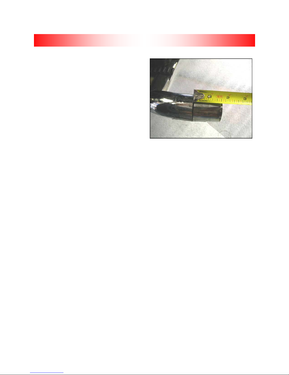
Fig. 1
Fig. 2
Right-side mount
LH Fork bracket bolts
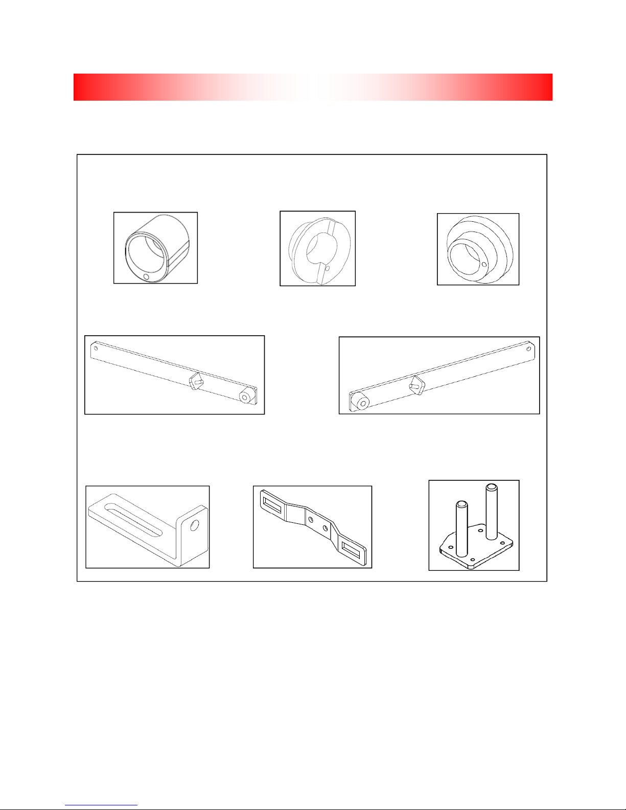
REMOVING HD SWINGARM
Pivot shaft nut
9