Leica Geosystems DX10 User manual


DX10
Field PC
DX10
Field PC
English
Leica DX10
User Manual
Version 1.0
English

DX10 Introduction2
en
Introduction
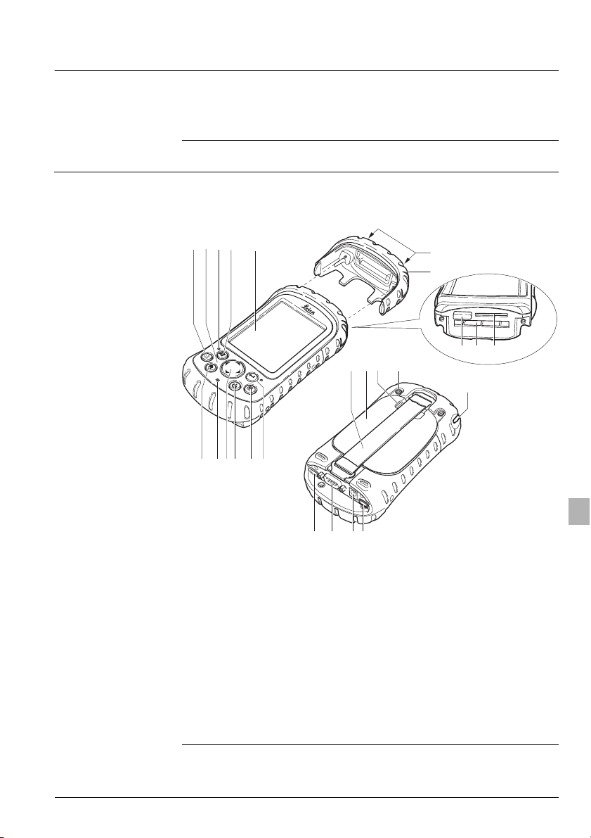
Purchase Congratulations on the purchase of a DX10 instrument.
This manual contains important safety directions as well as instructions
for setting up the product and operating it. Refer to "4 Safety Directions"
for further information.
Read carefully through the User Manual before you switch on the
product.
Product
identification
The type and the serial number of your product are indicated on the type
plate.
Enter the type and serial number in your manual and always refer to this
information when you need to contact your agency or Leica Geosystems
authorized service workshop.
Symbols The symbols used in this manual have the following meanings:
Trademarks • Windows, Windows CE, Windows Mobile, ActiveSync, Embedded
Visual C++ version 4.0, Visual Studio 2005 and VISTA are a registered
trademark of Microsoft Corporation
• Bluetooth is a registered trademark of Bluetooth SIG, Inc
All other trademarks are the property of their respective owners.
Type: _______________
Serial No.: _______________
Type Description
Danger Indicates an imminently hazardous situation which,
if not avoided, will result in death or serious injury.
Warning Indicates a potentially hazardous situation or an
unintended use which, if not avoided, could result in
death or serious injury.
Caution Indicates a potentially hazardous situation or an
unintended use which, if not avoided, may result in
minor or moderate injury and/or appreciable
material, financial and environmental damage.
)Important paragraphs which must be adhered to in
practice as they enable the product to be used in a
technically correct and efficient manner.

DX10 3Introduction
en
Available
documentation
)To use the DX10 efficiently it’s inalienable to refer to the manual
provided together with the software running on it. This is valid for
information on software upload also.
Name of
documentation
Description
DX10 User Manual All instructions required in order to operate the
product to a basic level are contained in this User
Manual. Provides an overview of the system
together with technical data and safety
directions.
Name of
documentation
Description
DX10 Technical
Reference Manual
Overall comprehensive guide to the system and
program functions. Included are detailed
descriptions of special software/hardware
settings and software/hardware functions
intended for technical specialists.
The Technical Reference Manual is available in
English only.
DX10 QuickGuide Describes the startup procedure for using the
DX10 Field PC and the PowerHolder.

DX10 Table of Contents4
en
Table of Contents
In this manual Chapter Page
1 Description of the System 5
1.1 The Anatomy of the Field PC 5
1.2 Suspend and resume the DX10 7
1.3 Using the stylus 8
1.4 Cables Used with DX10 9
1.5 Fixing the DX10-R to a PowerHolder and Pole 10
2 Getting Started 12
2.1 Step 1: Install the Battery Pack 12
2.2 Step 2: Charge the Battery Pack 13
2.3 Step 3: Establish Basic Settings on the Device 15
2.4 Step 4: Install ActiveSync on a Desktop Computer 16
2.5 Step 5: Create an ActiveSync Connection 17
3 Care and Transport 18
3.1 Transport 18
3.2 Storage 18
3.3 Cleaning and Drying 18
4SafetyDirections 19
4.1 General Introduction 19
4.2 Intended Use 19
4.3 Limits of Use 20
4.4 Responsibilities 20
4.5 End User Licence Agreement EULA 20
4.6 Hazards of Use 21
4.7 Electromagnetic Compatibility EMC 24
4.8 FCC Statement, Applicable in U.S. 26
5TechnicalData 28
5.1 DX10 Technical Data 28
5.2 PowerHolder Technical Data 31
5.3 Conformity to National Regulations 32
6 International Limited Warranty, Software License
Agreement 33

DX10 5Description of the System
en
1 Description of the System
General Designed for Windows Mobile 5.0, your Field PC features a wide variety
of application software choices. Use it to navigate, research, document,
and communicate. Depend on it for your field information technology. It
is ready for you.
1.1 The Anatomy of the Field PC
Components of the
DX10
This section illustrates the different parts of your Field PC. For more
details about using the Field PC, see the Technical Reference Manual on
the User Documentation CD.
a) Applications Manager button
b) Microphone
c) Charge LED
d) Start menu button
e) Touchscreen/display
f) Today screen button
g) Speaker
h) Four-way directional button
i) Power button
j) Context menu button
k) Enter button
l) Top cap screws (captive)
m) Top cap
n) Cover for optional Bluetooth
antenna
o) Compact Flash card slot
p) Secure Digital I/O card slot
q) Hand strap
r) Battery door
s) Battery door latch
t) Accessory attachment points
u) Stylus
v) USB Host (mini A)
w) 9-pin serial port
x) 12V DC jack
y) USB Client (mini B)
DX10
l
abcd e
fghijk
m
no p
rs t
u
vwxy
q
DX10_01

DX10 Description of the System6
en
Available DX10
types
Your Field PC is available as DX10-R and DX10-Y. Differences between
these types are shown in this segment.
)• For DX10-Y, clip and accessories are delivered in a separate package
while angle bracket is not available.
• General illustrations show a DX10-Y, without clip.
Mounting the clip
onto DX10-Y
Use the mounting screw together with the washer to mount the clip and
the spacer onto the DX10-Y.
DX10-R DX10-Y
DX10-R is delivered with following additional parts mounted:
a) Clip and accessories
b) Angle bracket
DX10_12
b
a
a) Clip
b) Screw
c) Washer
d) Spacer
DX10_14
a
b
c
d

DX10 7Description of the System
en
Identifying button
functions
The following chart shows you the names and functions of each button
on the keyboard.
1.2 Suspend and resume the DX10
Button Name Function
Start menu button Provides a menu of applications.
Applications
Manager button
Lets you switch between or close
running applications; allows you to view
memory allocations.
Home button Returns you to the Today screen.
Context menu
button
Displays the context menu for the item
selected (similar to a right-click on a
desktop computer).
Enter button Enters the selected soft key or option.
Power button Turns the Field PC on and off, resets,
suspends.
Four-way
directional button
Allows you to navigate.
4sec.
1sec.
1x
1x
1x
1x
ULTRA-RUGGET
FIELD PC

DX10 Description of the System8
en
1.3 Using the stylus
Using the stylus Like the left button on a desktop computer mouse, the stylus is a tool
that lets you select or deselect items and enter data. Like the right
button, the stylus lets you perform shortcuts like cutting and pasting.
Instructions for these tasks are listed in the chart below.
For instructions on using the transcriber program on your Field PC, see
Entering Information in Technical Reference Manual, Chapter 4.
The stylus is stored in an open slot at the top of the device. A hole in the
stylus end allows you to attach a lanyard.
To do this . . . Follow these steps
Select an item Tap once.
Open an item or file Tap the item or file.
Open a context
menu for an item
Tap and hold the item. The context menu
appears.
Cut or copy 1. Tap and hold until the context menu appears.
2. Select Cut or Copy.
Paste 1. Tap and hold the area where you want to
paste.
2. Select Paste from the context menu that
appears.
Drag and drop 1. Tap and drag the item to the destination.
2. Lift up the stylus.
Select multiple items Drag the stylus over the items.

DX10 9Description of the System
en
1.4 Cables Used with DX10
Cables available
)• Disconnect DX10-R from PowerHolder before charging the DX10.
• If DX10-R is used on the PowerHolder be sure that only the 9 PIN
SubD connector is plugged to DX10.
• Use only cables recommended by Leica Geosystems.
Name Description Length
USB 2.0 A to MINI B 2 m
GEV102 Data Cable, Lemo0 (5 pin) to RS232
(9 pin)
2 m
GEV160 Data Cable, Lemo1 (8 pin) to RS232
(9 pin)
2.8 m
GEV187 Y-Cable, Lemo0 (5 pin) to Lemo0
(5 pin) + RS232 (9 pin)
2 m

DX10 Description of the System10
en
1.5 Fixing the DX10-R to a PowerHolder and Pole
Components of the
PowerHolder
The PowerHolder consists of a number of components, as shown in the
diagram.
Fixing the DX10-R
and PowerHolder
to a pole step-by-
step
GHT52 clamp
a) Plastic sleeve
b) Pole clamp
c) Clamp bolt
PowerHolder
d) Tightening screw
e) Mounting arm
f) LED
g) Mounting plate
h) Safety screw
i) Cable to connect DX10 (9 PIN SubD connector)
j) Battery compartment
k) Locking mechanism for battery
l) Space for clip-on-housing with LEMO port
DX10_08
c
b
d
e
g
f
h
j
a
k il
Description
1. Remove holder from the travel container.
2. A plastic sleeve may be required to be fitted to the pole clamp.
3. Insert pole into the clamp hole.
4. Adjust the angle of the mounting plate and the height of the holder
on the pole to comfort.
5. Tighten the clamp with the tightening screw.
)Once tightened, the button on the tightening screw can
be depressed to change the position of the handle for
more comfort.
)A locking mechanism is incorporated in the mounting
plate of the holder.

DX10 11Description of the System
en
Detaching the
DX10-R from a pole
step-by-step
6. Attach the clip at top end of
DX10 against the pivot on
PowerHolder. Lower DX10 into
the holder.
7. After DX10 is placed into the
holder ensure that the safety
screw under the PowerHolder is
screwed into the bracket on the
DX10.
8. Plug in connector to DX10.
Secure connector with safety
screws.
Description
DX10_09
DX10_11
DX10_10
Description
1. Unplug connector from DX10.
2. Screw out the safety screw of the bracket on the DX10.
3. Push the DX10 towards top of the PowerHolder to release the
clip from the pivot.
)Always disconnect the cable between the DX10 and the
PowerHolder when the DX10 is not in use (over night, etc.).

DX10 Getting Started12
en
2 Getting Started
General This chapter repeats — with a few more details — the installation
instructions in the Quick Start Guide that came with your Field PC.
2.1 Step 1: Install the Battery Pack
Install the Battery
Pack, step-by-step
Step Description
1. Carefully unhook and lift up the bottom hook of the hand strap,
as shown in the first picture.
)Releasing the hand strap hook too quickly may result in injury
or damage to the display. Use caution when undoing the hook
or when holding the Field PC by its hand strap.
2. Press on the battery door and slide the door latch to the right
to unlock it.
3. Remove the battery door.
4. Insert the battery pack so battery contacts match up.
5. Insert the tabs on the bottom of the battery door into the case
slots. Close the battery door.
6. Press on the battery door. Slide the latch to the left to lock it.
7. Reattach the hand strap.
1
1
2
3
4
5
6
DX10_02

DX10 13Getting Started
en
2.2 Step 2: Charge the Battery Pack
Charging/first-time
use
For Li-Ion batteries:
• The batteries must be charged prior to using for the first time
because it is delivered with an energy content as low as possible.
• The permissible temperature range for charging is between 0°C to
+40°C /+32°F to +104°F. For optimal charging we recommend
charging the batteries at a low ambient temperature of +10°C to
+20°C/+50°F to +68°F if possible.
• It is normal for the battery to become warm during charging. Using
the chargers recommended by Leica Geosystems, it is not possible to
charge the battery if the temperature is too high.
• For new batteries or batteries that have been stored for a long time
(> three months), it is effectual to make only one charge/discharge
cycle.
• For Li-Ion batteries, a single discharging and charging cycle is
sufficient. We recommend carrying out the process when the battery
capacity indicated on the charger or on a Leica Geosystems product
deviates significantly form the actual battery capacity available.
Operation/
Discharging
• The batteries can be operated from -30°C to +50°C / -22°F to
+122°F.
• Low operating temperatures reduce the capacity that can be drawn;
very high operating temperatures reduce the service life of the
battery.
Charge the Battery
Pack, step-by-step
Step Description
1. Mount the plug onto the wall charger (if it is not already
assembled).
2. Plug the wall charger into an outlet.
3. Plug the other end of the wall charger into the DC jack of the
Field PC.
4. The device turns on after a few seconds, and a flashing red
light signals the device is charging.
DX10
1
3
2
3
DX10
46h
DX10_03

DX10 Getting Started14
en
Warning Batteries not recommended by Leica Geosystems may be damaged if
charged or discharged. They may burn and explode.
Precautions:
Only charge and discharge batteries recommended by Leica Geosystems.
Charger:
Danger The product is not designed for use under wet and severe conditions. If
unit becomes wet it may cause you to receive an electric shock.
Precautions:
Use the product only in dry environments, for example in buildings or
vehicles. Protect the product against humidity. If the product becomes
humid, it must not be used !
)Charging the Field PC for 4.5 hours charges it up to 95%. Let
the device charge for 6 hours to get a full charge.
If the Field PC suspends and the flashing red LED turns off, the
device keeps charging.
Step Description

DX10 15Getting Started
en
2.3 Step 3: Establish Basic Settings on the Device
Basic Settings,
step-by-step
Using the stylus, follow the instructions on the screen to calibrate the
device and establish basic settings.
We recommend creating a name for the Field PC so external devices like
desktop computers or Bluetooth devices can differentiate it from other
devices more easily.
To create a name, follow these steps:
Your Field PC is now field ready. If you have Windows 2000 or Windows
XP, follow the next steps to install ActiveSync, which allows you to install
programs onto your device using a desktop computer.
Note to Microsoft Windows Vista users:
You have basic file synchronization capability with your desktop
computer without installing any additional software. To access these
basic sync options, connect the Field PC to the desktop computer using
a USB cable. For full synchronization support such as Microsoft Outlook
)Windows Mobile is pre-installed on the DX10 in English
language. For other language options of Windows Mobile oper-
ating systems, please consult the support/downloads section
on the website: www.junipersys.com.
Step Description
1. Tap Start > Settings.
2. From the System tab, tap About. The About window appears.
3. Select the Device ID tab at the bottom of the screen.
4. Type in a device name. An example of a device name appears
below.

DX10 Getting Started16
en
contacts, email, calendar, notes, and tasks, download and install
Windows Mobile Device Center through Windows Update on the Start
menu of your desktop computer.
2.4 Step 4: Install ActiveSync on a Desktop Computer
Install ActiveSync,
step-by-step
If you use Windows 2000 or Windows XP, Windows Mobile 5.0 requires
that you use Microsoft ActiveSync 4.1 or higher to connect to your
desktop computer. The Getting Started Disc installs ActiveSync 4.5 on
your desktop computer.
Step Description
1. Insert the Getting Started Disc into your desktop computer. A
window appears on the display, as shown.
2. Select your language.
3. If ActiveSync 4.5 or higher has not been installed on your
desktop computer, follow the directions on the screen to install
it.
)Install ActiveSync before attaching the USB cable to the
desktop or Field PC.

DX10 17Getting Started
en
2.5 Step 5: Create an ActiveSync Connection
ActiveSync
Connection, step-
by-step
You are now ready to use your Field PC. See the Technical Reference
Manual on the User Documentation CD for instructions on specific tasks.
Step Description
1. Plug USB Client end (mini B) of the USB communications cable
into your Field PC.
2. Plug the USB Host end (full size A) of the USB communications
cable into your desktop computer.
3. Establish an ActiveSync partnership by following the
instructions on the desktop computer screen.

DX10 Care and Transport18
en
3 Care and Transport
3.1 Transport
Transport in a road
vehicle
Never carry the product loose in a road vehicle, as it can be affected by
shock and vibration.
Shipping When transporting the product by rail, air or sea, always use the
complete original Leica Geosystems packaging, transport container and
cardboard box, or its equivalent, to protect against shock and vibration.
Shipping, transport
of batteries
When transporting or shipping batteries, the person in charge of the
product must ensure that the applicable national and international rules
and regulations are observed. Before transportation or shipping, contact
your local passenger or freight transport company.
3.2 Storage
Product Respect the temperature limits when storing the equipment, particularly
in summer if the equipment is inside a vehicle. Refer to "5 Technical
Data" for information about temperature limits.
Li-Ion batteries • Refer to "5 Technical Data" for information about storage
temperature range.
• At the recommended storage temperature range, batteries
containing a 10% to 50% charge can be stored for up to one year.
After this storage period the batteries must be recharged.
• Remove batteries from the product and the charger before storing.
• After storage recharge batteries before using.
• Protect batteries from damp and wetness. Wet or damp batteries
must be dried before storing or use.
• A storage temperature range of -20°C to +30°C /-4°F to +86°F in a
dry environment is recommended to minimize self-discharging of the
battery.
3.3 Cleaning and Drying
Product and
Accessories
• Use only a clean, soft, lint-free cloth for cleaning. If necessary,
moisten the cloth with water or pure alcohol.
Do not use other liquids; these may attack the polymer components.
Charger Use only a clean, soft, lint-free cloth for cleaning.
Cables and plugs Keep plugs clean and dry. Blow away any dirt lodged in the plugs of the
connecting cables.
Table of contents
Languages: