A-BUS SYSTEM OVERVIEW:
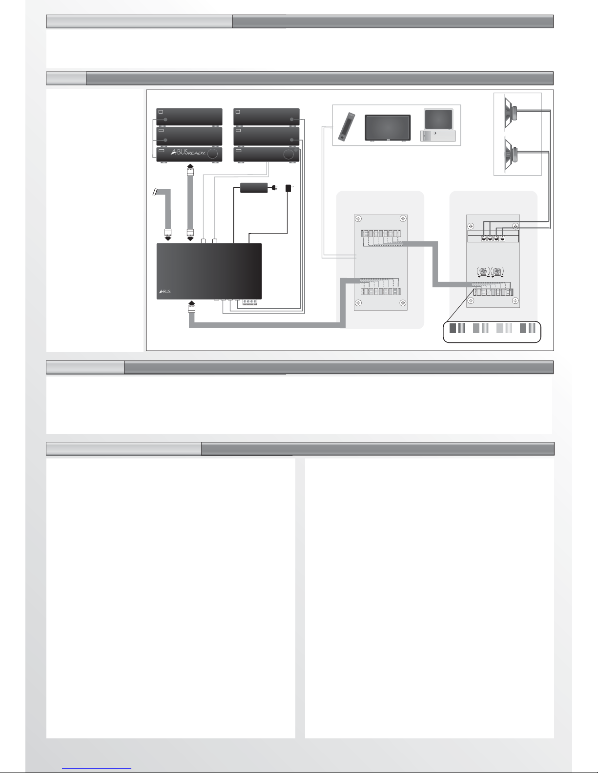
A-BUS Hub: The A-BUS hub is the core of the system, distributing
audio signal, system power and status indication to A-BUS power
modules installed in rooms throughout the home and sends IR
commands from the power modules back to the source
components. It is usually located near the main sound system
(Amplifier/Receiver, CD, DVD, Tape, Cable, etc.) Typically they have
four room outputs with expansion ports (IN/OUT) so multiple hubs
can be connected to tailor the system to individual requirements.
FEATURES:
· Audio input from the main amplifier’s tape output or second zone output.
· 4 Infrared (IR) outputs to remote controllable source
components and the main amplifier (to allow for input selection).
Single/Dual emitters may be used (EM-1/EM-2).
· Power supply for system power (supplied). (Should not be
connected to the amplifiers switched output.)
· Status optional (see below).
· Room outputs to go to four A-BUS power modules.
· Expansion ports – to add additional rooms
OUT: Connects to additional hubs to add more rooms.
(Each hub requires it’s own power supply)
IN: Connects to the direct input of an A-BUS/READY amplifier
Connects to an A-BUS input selector
· Local infrared input to relay IR commands if the main system
amplifier is concealed (single zone amplifiers only).
A-BUS Power Modules: A-BUS power modules are stereo
amplifiers with level control that power a pair of speakers in each
room. Only one DataLine cable is required between the hub and the
power module. Speaker cable is run from the power module to the
speakers except when the A-BUS power module is located on the
speaker itself. Standard rotary A-BUS power modules do not include
infrared repeating. IR-equipped modules relay 38KHz codes to the
source components for input track/channel selection, etc. They also
include infrared talkback and status indication. An LED indicator
indicates when the A-BUS system is on (See Power/Status below)
and it flashes signifying an infrared command has been received.
The volume level on touch-button A-BUS modules can also be
operated by the ABR-60 remote control handset. The IR repeater
system is always active regardless of system status.
Audio, IR Data and Status Connections: A-BUS/READY
amplifiers are equipped with an RJ-45 A-BUS output socket
enabling direct connection to either a single A-BUS power module
for one extra zone or to an A-BUS hub for multiple rooms in an
extra zone. The A-BUS/READY outlet supplies audio, status and
infrared data connection. Some A-BUS/READY amplifiers can
power one power module independently while others require a
separate power supply.
IMPORTANT: When purchasing a new amplifier or home theater
receiver look for the A-BUS/READY logo on the front. That means a
simple RJ-45 connection on the back immediately connects you to
the whole-house system, as long as the house is wired for A-BUS.
Power/Status: There are several ways to activate an A-BUS system.
When not in operation the A-BUS system is in standby mode. It is
activated by:
·Automatic Signal Sensing (Default): The Hub automatically detects
when audio signal is present and activates the A-BUS system.
30-seconds after the audio signal ends the system returns to standby.
·Main System Sensing (Preferred): A-BUS also activates automatically
when the main sound system is switched on (including source
components). A PS-1 power pack should be plugged between the
main amplifier’s switched power outlet and the hub’s Status input.
·A-BUS/READY: The hub can be directly connected to an
A-BUS/READY amplifier via the Expansion Input port. The A-BUS
system automatically powers up when an A-BUS/READY amplifier is
switched on. This may be done via remote control from any room.
Note: The hub power supply is still required.
A-BUS Local Input Module (LIM): The LIM provides "local" input
capability for sources such as TV sound, MP3 player, computer sound
cards, etc. located in the zone. The LIM automatically switches to the
local input when a local source is detected. 30-seconds after the local
source ceases, the LIM automatically reverts to the main input source.
The LIM is easy to install. Note - Care should be taken during pre-wire to
run the DataLine cable from the hub to the power module via the LIM
installation point. This is often a forgotten requirement, e.g. In the case of
a local TV, the DataLine cable should be run past the room's aerial point.
A-BUS Four-Way Input Switcher: The four-way input switcher can
be used in a number of ways (see separate instruction sheet). It can be
used as an input switcher eliminating the need for an amplifier to select
sources. In addition to the four inputs there are four active outputs that
extend the source signals to a main system amplifier without signal loss.
With this configuration the A-BUS system has separate source selection
to the main system creating an independent zone. Multiple input
switchers may be used to create more sophisticated multi-source
systems. Keep in mind that a separate hub is required with each input
selector. Input selection is accomplished via A-BUS infrared commands.
A-BUS COMPATIBILITY
This product complies with the A-BUS format. The A-BUS format has
been adopted by other manufacturers who make a variety of products
that can give your system added flexibility. When looking to expand
and/or upgrade your home entertainment system, be sure to look for
products that carry the A-BUS trademark.
PRODUCT INSTALLATION NOTES
· All A-BUS RJ-45 connectors are wired to the 568A standard.
· The colour code order of punchdown connectors may vary.
· Standard A-BUS DataLine patch leads may be used.
· The infrared system will relay 38KHz commands.
IMPORTANT: Substitute power supplies are not recommended.
Pre-Wiring: All cabling between the A-BUS/READY amplifier/interface
module, distribution hubs and power modules should be A-BUS
DataLine cable. The recommended maximum cable run is 30M.
Andrew’s Audio Low Loss Speaker Cable should be run from the power
module point to the speaker points; however, it is recommended that the
A-BUS DataLine cable be extended to the speaker points as well to allow
for the installation of an A-BUS/DIRECT speaker system which has the
power module incorporated in the speaker (A-BUS power modules will
accept up to14 gauge cable). It is recommended that all DataLine
cables at the hub end be terminated with wall mounted RJ-45 sockets
with standard (568A) patch leads between the wall socket and the hub.
NOTE: Before installing the DataLine cables check for Local Input
Module requirements. Eg. in the case of a local TV, the DataLine cable
should be run past the room's antenna connection point. A 1M taped
loop of cable for access is recommended. The same could be applied to
a point in a child's room next to a desk where a computer or MP3 player
may be located.
IMPORTANT: These instructions contain directions for installers of
A-BUS systems. The manufacturer or its agents shall not be liable to
any person or entity for loss or damage, including consequential loss
or damage, arising out of any error or fault in the installation of the
A-BUS system or any of its component parts.
Welcome to A-BUS Multi-Room Audio. When combined with
your source equipment (receiver, CD player, etc.) and
speakers, A-BUS creates a versatile whole-house audio system
that will fill your home with high-quality music for years to come.
A-BUS Installation Instructions
For Custom Installations