Contents
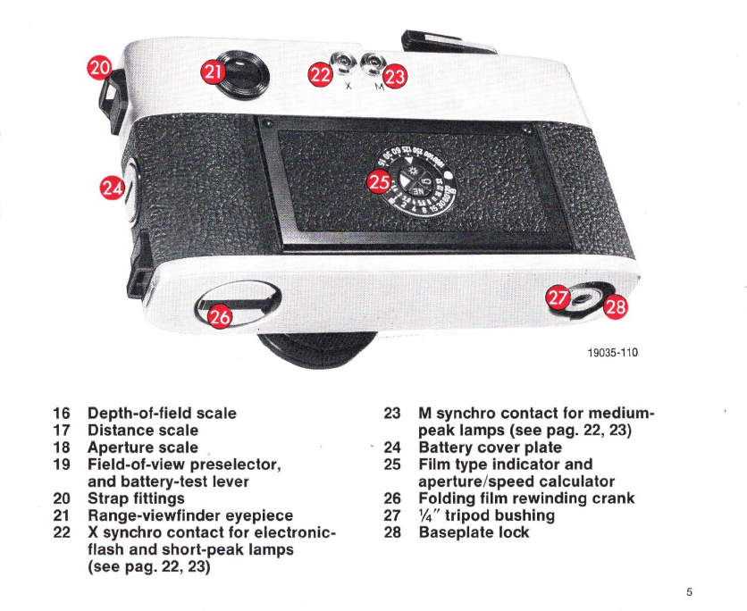
LEICA M 5 parts identification
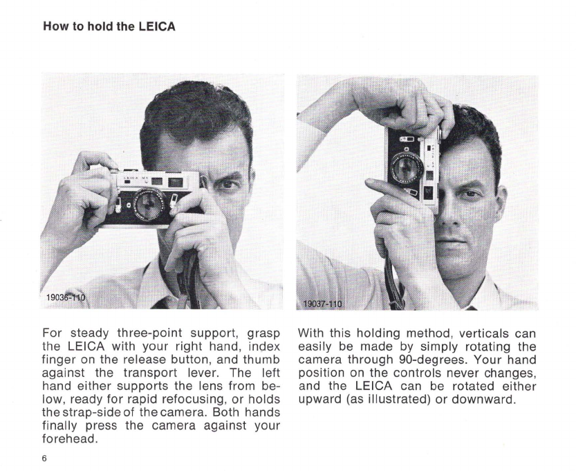
How to hold the LEICA
The bright-line range-viewfinder
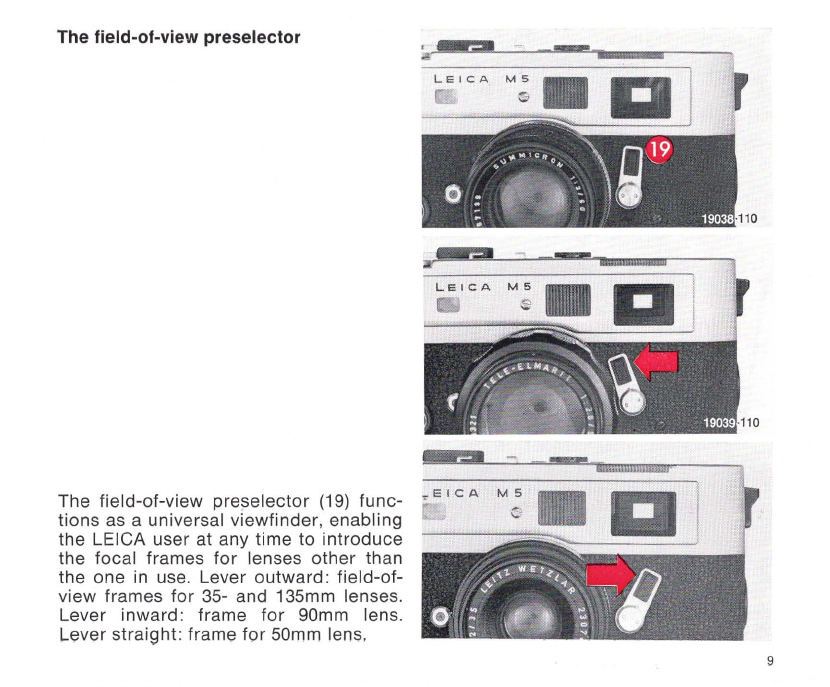
The field-of-view preselector
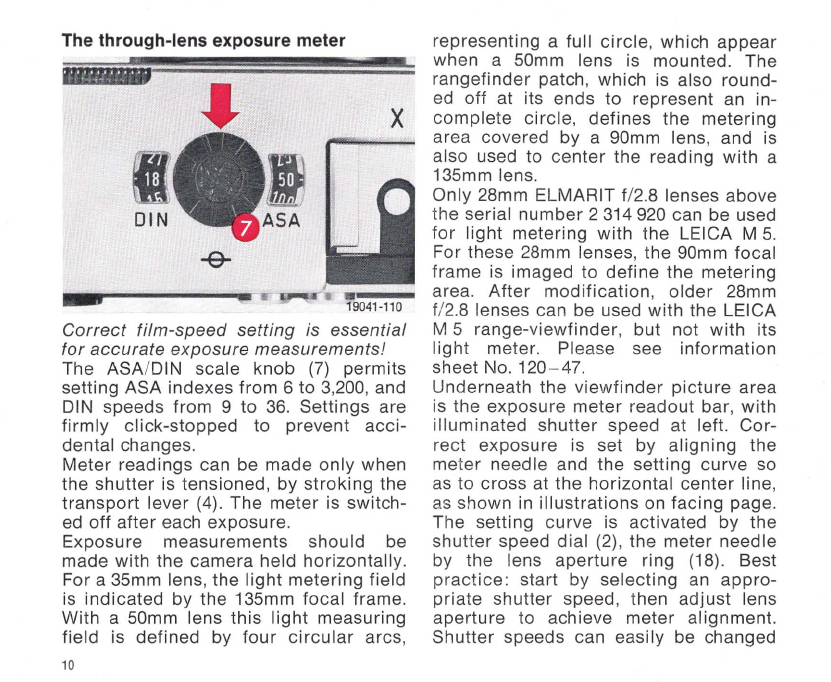
The built-in exposure meter
Battery, and Battery test
Using filters
Close-up
pictures
The rangefinder
Transport
lever, Release button,
Page
4
6
7
9
10
14
15
15
16
Shutter speed
selector
18
The depth-of-field scale
19
The distance and aperture scales
20
Lens changing
21
Self-timer, Flash synchronization
22
Flash table
23
Film loading
24
Film removal
25
Protecting your LEICA, and its lenses
26
Page
The LEICA system
Interchangeable LEICA lenses
27
VISOFLEX
28
Bellows and close-focusing devices
29
Extreme tele-Ienses, Cases
30
LEICA Information Service
33
LEITZ Warranty
34
After-sales Service,
Magazine "LEICA FOTOGRAFIE"
35
3