27July2015/Version 5 Page 2 /15
TABLE OF CONTENTS
TABLE OF CONTENTS ................................................................................................................................2
LIST OF FIGURES........................................................................................................................................2
LIST OF TABLES..........................................................................................................................................2
1. INTRODUCTION.......................................................................................................................................3
2. WARRANTY STATEMENT.......................................................................................................................4
3. RECEIVING AND UNPACKING................................................................................................................5
4. TECHNICAL SPECIFICATIONS...............................................................................................................6
5. SYSTEM DESCRIPTION..........................................................................................................................7
5.1 FRONT PANEL....................................................................................................................................8
5.2 INDICATOR PANEL ............................................................................................................................8
5.3 BACK PANEL ......................................................................................................................................9
5.4 TRANSDUCER PORT.........................................................................................................................9
5.5 CONNECTING THE TRANSDUCERS..............................................................................................10
5.6 OUTPUT PORT.................................................................................................................................11
6. INSTALLATION ........................................................................................................................................14
7. OPERATING INSTRUCTIONS ...................................................................................................................15
8. MAINTENANCE.........................................................................................................................................15
LIST OF FIGURES
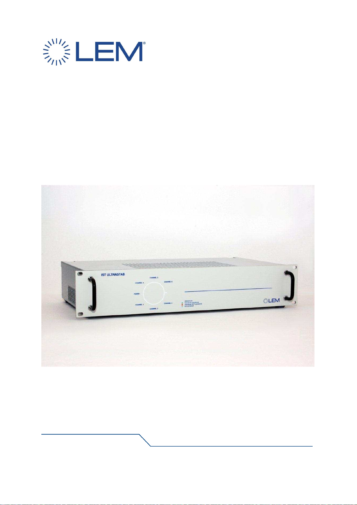
FIGURE 1: An overview of the front panel, with a close-up of the indicator panel .......................................8
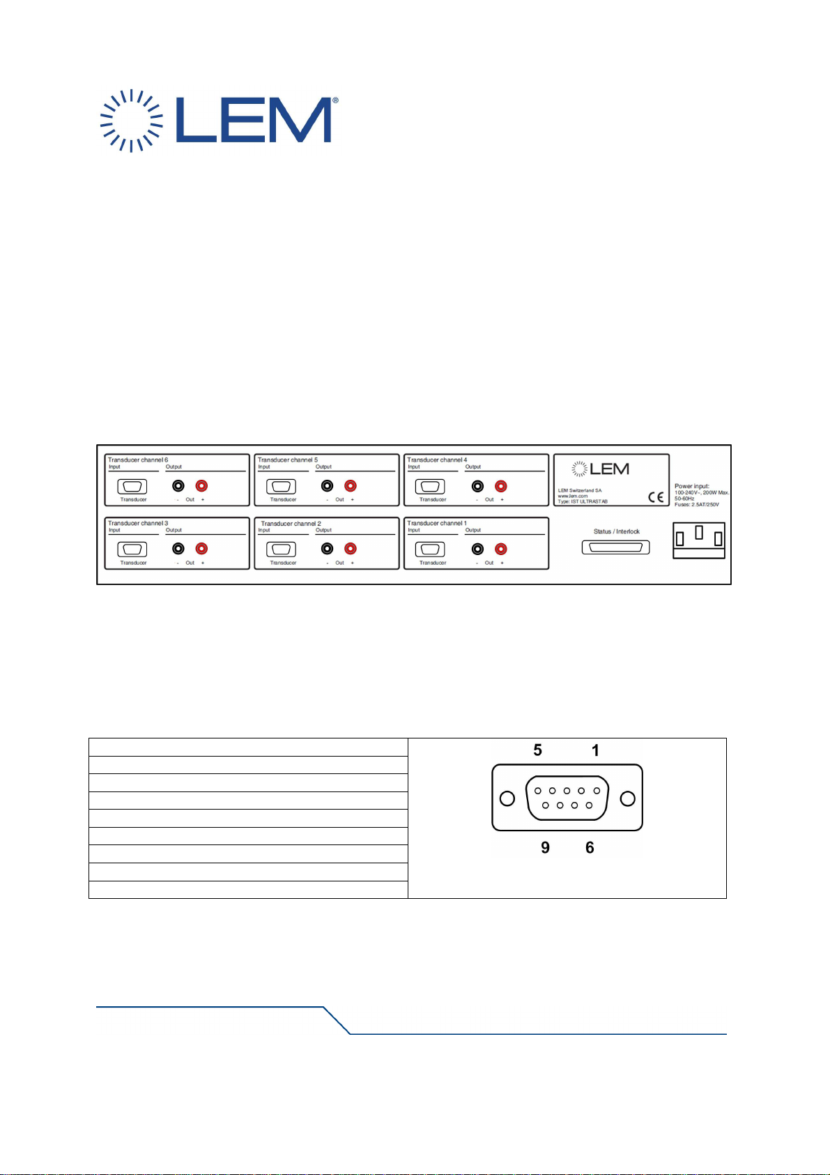
FIGURE 2: Overview of the IST ULTRASTAB back panel ...........................................................................9
FIGURE 3: Pin out for 9-pin transducer connector .......................................................................................9
FIGURE 4: Connecting a transducer to IST ULTRASTAB..........................................................................10
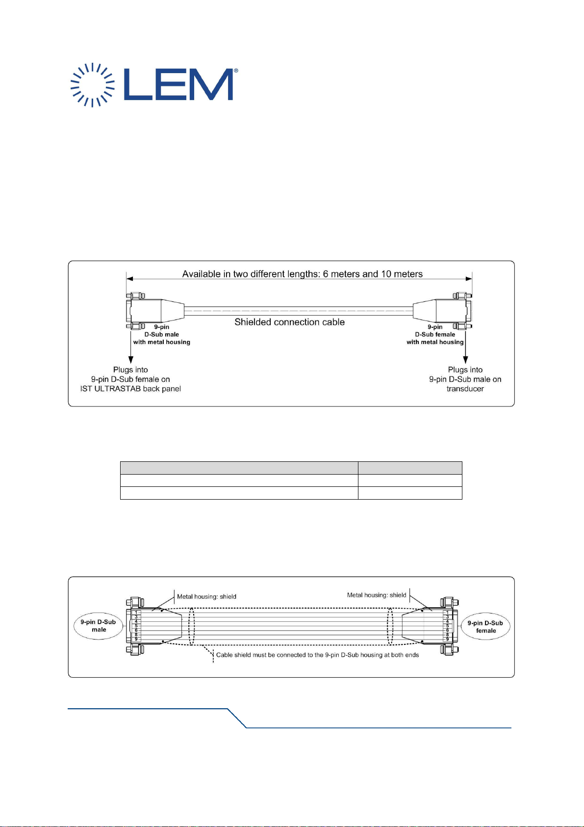
FIGURE 5: Transducer to IST ULTRASTAB connection cable wiring........................................................10
FIGURE 6: Output terminals........................................................................................................................11
FIGURE 7: Status/Interlock port Wiring.......................................................................................................12
FIGURE 8: Pin out for 15-pin status connector...........................................................................................13
FIGURE 9: IST ULTRASTAB in a typical 3-channel current output application .........................................14
LIST OF TABLES
TABLE 1: Technical specifications................................................................................................................6
TABLE 2: IT/ITN ULTRASTAB compatibility chart........................................................................................7
TABLE 3: Two shielded connection cables available for connecting the transducers................................10
TABLE 4: Recommended standard values of R.........................................................................................13