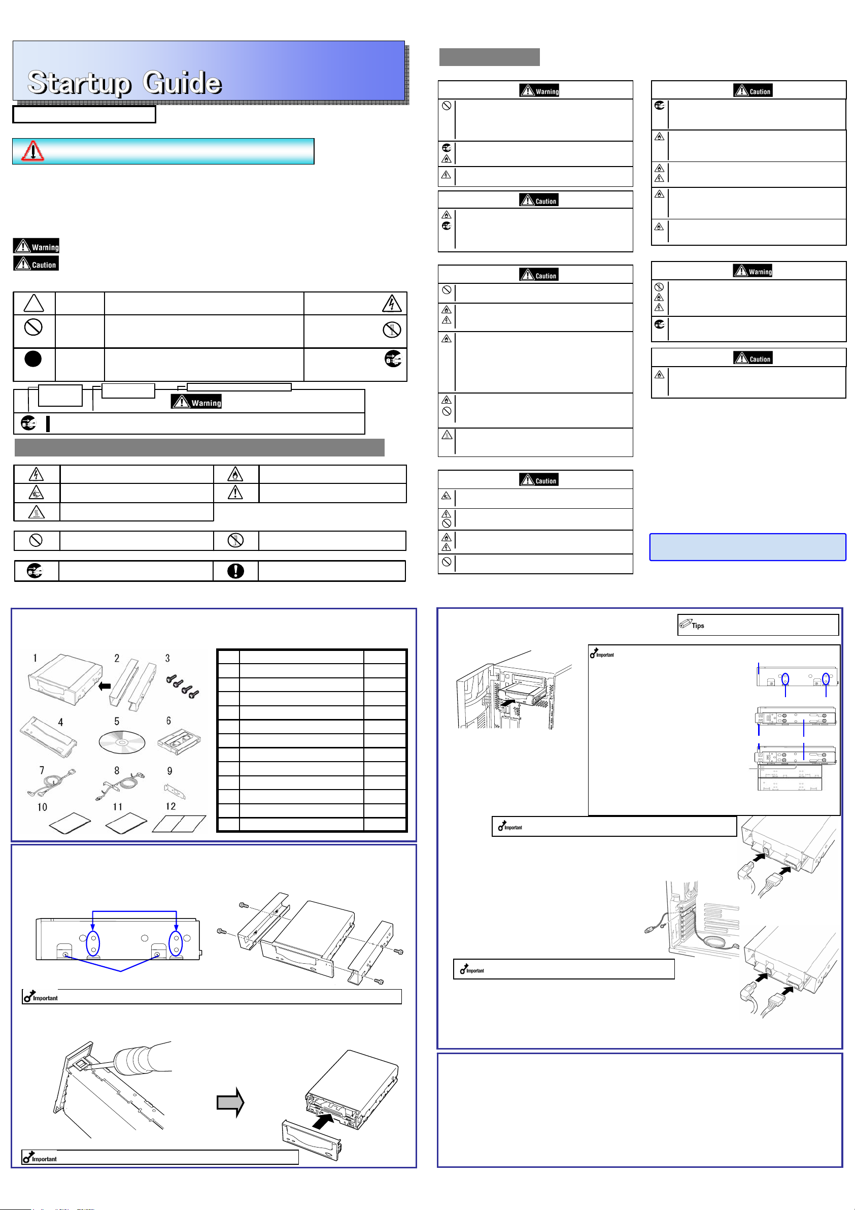
3. Mounting on the Basic Processing Unit
The procedure for installing the drive in a server is as follows.
●Connecting the Drive to the Server with INT USB Cable
(1) Install the Built-In DAT as shown here.
(2) Connect the 10-pin connector of INT
USB interface cable to the USB
connector on mother board.
Connect the 4-pin connector of
branched cable to the FDD
connector, and the USB connector
on the other end to the USB
connector of Builtin DAT (USB).
(3) Connect the cables to the drive as shown in the figure below.
Use the INT USB cable provided with the device.
●Connecting the Drive to the Server with EXT USB Cable
(1) Install the Built-In DAT as shown here.
(2) Secure the EXT USB interface cable to the PCI slot
in the server, as shown in the figure below.
(3) Connect the cables to the drive as shown in the figure below.
Use the EXT USB cable provided with the device.
4. <Using the ASR function>
When using the ASR (Automated System Recovery*) function in Windows, you must download and install the
device driver files from a floppy disk. Prepare a blank floppy disk, and copy the files in the “Tape Driver” folder
on the supplied CD to the blank floppy disk.
The TapeDriver folder itself shall not be included in the directory tree.
*ASR (Automated System Recovery)
Supported by Windows XP and Windows Server 2003, this function backs up the OS, system state, hardware
composition, and applications on your computer, allowing you to restore them in one step when recovering from
a crash. For more details on using this function, refer to the manual for your OS and backup software.
Windows 2000 does not support the ASR function.
DC power cable
(unused power supply
connector in the
computer)
・When using the rails with this device, use the
screw holes in the front cover illustrated in Fig. 1
(see Fig. 2). (Perform the same operation on the
opposite side. Secure two screws on each side,
four screws total.)
In some cases the rails may extend all the way to
the front cover molding. This causes no
problems.
When using the rails, adjust their mounting
positions so that the front cover of this device is
aligned with the front covers of other standard
components (such as the CD-ROM drive).
(The shape of the rails varies according to the
model of the device.)
・The screws needed with the 5.25-in and 3.5-in
devices are the same.
・Always use the screws that are provided with
this device. The screws that are provided with
this device are metric screws (length: 4.0 mm).
Using screws that are longer than the screws
that are provided with this device could result in
damage to the device.
However, you may be required to use screws
coming with the basic processing unit. Refer to
the User's Guide of the basic processing unit.
INT.USB
interface cable
OFD N8151-69 Built-In DAT(USB)
Read me first 856-850858-001- A October,2006 First edition
This Startup Guide describes the instruction until the device become ready to use.
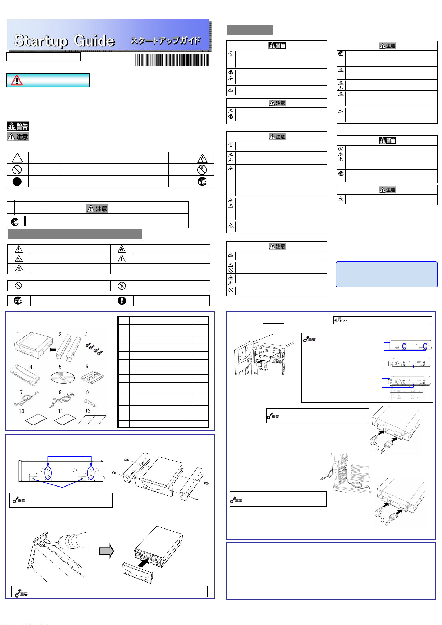
1. Verify the packed contents
2. Change procedure to 3.5-in device
When you want to use the Built-In DAT as a 3.5-in device, you need to remove the left and right brackets.
(1) To Remove the Brackets
Using a Phillips screwdriver, remove the screws, and then the brackets.
(2) Replacing the Front Panel
1Guarantee12
1Instructions on handling the DAT unit11
1Startup Guide (this manual )10
1Low Profile Brackets9
1EXT.USB cable8
1CD (Device driver ,User’s Guide)5
1INT.USB cable7
1Cleaning cartridge6
1Front panel (for 3.5-inch device)4
4Screws3
2Brackets ※installed2
1N8151-69 Built-In DAT(USB)1
Qty.Parts name
Mounting screw holes
Bracket screws
Make sure that you store the brackets and screws in a safe place. Only use these screws when installing the brackets. They are
metric screws (length: 4.0 mm). Using longer screws could result in damage to the device.
Insert a Phillips screwdriver into the hooks on
both sides of the front panel to release the
hooks.
To install a front panel, align the cartridge slot of
the front panel with that of the basic processing
unit, and push the front panel straight to the basic
processing unit to engage until it clicks.
Hooks are hidden by the aluminum dust-proof seal. Peel off the seal partially.
When you replaced the front panel, stick the dust-proof seal as before.
(4)After connecting the USB cable, bundle the cable so that it does not
interfere with the other devices or fan.
(5) Attach the cover to the basic processing unit. Plug the
power cable to the outlet.
(6) Turn on the basic processing unit.
Some servers require the rails to be used. For
details on how to install the rails, refer to the
server's operating manual.
Please keep it carefully.
The contents of this document may be changed without notice.
Screw holes
Rail
Fig.3
Fig.2
Front cover Fig.1
Front cover
Verify the packed contents with the part list given below and ensure that all the components and parts are
present. Also, check that each item is undamaged. If a component or part is missing or damaged, contact
your dealer.
Safety Considerations - Must Read -
Follow the instructions given in this Startup Guide for proper operations and safe use of the device.
SAFETY INDICATIONS
This Startup Guide describes the device components with possible danger, hazards that may be caused by ignoring
warnings, and preventive actions against such hazards.
Components with possible danger are indicated with a warning label placed on or around them. In the User's Guide
or warning labels, "WARNING" or "CAUTION" is used to indicate a degree of danger. These terms are defined as
follows:
Failure to heed this sign could result in serious injury or death.
Failure to heed this sign could result in personal injury or damage to properties.
(Sample)
(Disconnect the power cord)
This symbol indicates mandatory actions.
An image in the symbol illustrates a mandatory action to avoid a
particular hazard.
Mandatory
Action
(Sample)
(Do not touch the part)
This symbol indicates prohibited actions.
An image in the symbol illustrates a particular prohibited action.
Prohibited
Action
(Sample)
(Electric shock)
This symbol indicates the presence of a hazard if the instruction is
ignored. An image in the symbol illustrates the hazard type.
Attention
(Sample)
Do not install the device while the power is turned on.
Unplug the AC power cord from the main power source when installing/uninstalling the device to/from basic processing unit or connect it with the
enclosure. Failure to follow this warning may cause an electric shock.
A symbol for
arousing
attention
A term indicating a hazard level
A content of
possible danger
Attention
Indicates a general notice or warning that cannot be specifically
identified.
Indicates that improper use may cause fingers to be caught.
Indicates that improper use may cause fumes or fire.Indicates that improper use may cause an electric shock.
Prohibited Action
Do not disassemble, repair, or modify the device. Otherwise, an
electric shock or fire may be caused.
Indicates a general prohibited action or warning that cannot be
specifically identified.
Mandatory Action
Indicates a general mandatory action or warning that cannot be
specifically identified.
Unplug the power cord. Otherwise, an electric shock or fire may be
caused.
SYMBOLS USED IN THIS USER'S GUIDE AND WARNING LABELS
Indicates that improper use may cause personal injury.
Precautions and notices against hazards are presented with one of the following three symbols. The individual
symbols are defined as follows:
SAFETY NOTES
General Attention
Do not use in life-critical applications or applications requiring high reliability.
This device is not intended for integration with or control of facilities or equipment
that may affect human life or that require a high degree of reliability, such as medical
equipment, nuclear power facilities, aerospace instruments, and transportation
equipment. The manufacturer does not assume any liabilityfor accidents resulting in
injury or death, or for any damages to property that may occur as a result of using
this device in such facilities, equipment, or control systems.
Do not use the Built-in DAT if any smoke, odor, or noise is present.
If smoke, odor, or noise is present, immediately turn off the POWER switch and
disconnect the power plug from the outlet, then contact your sales agent. Using the
Built-in DAT in such conditions may cause a fire.
Keep water or foreign matter away from the Built-in DAT.
Do not let any kind of liquid (water etc.) or foreign matter (e.g.,pins or paper clips)
enter the Built-in DAT. Failure to follow this warning may cause an electric shock, a
fire, or a failure of the Built-in DAT. When such things accidentally enter the Built-in
DAT, immediately turn off the power and disconnect the power plug from the outlet.
Do not disassemble the Built-in DAT. Contact your sales agent.
Attention to Power or Power Cord
Do not install the device while the power is turned on.
Unplug the AC power cord from the main power source when installing/uninstalling
the device to/from basic processing unit or connect it with the enclosure. Failure to
follow this warning may cause an electric shock.
Insert the DC cable into the outlet as far as it goes.
Heat generation resulting from a halfway inserted DC cable (imperfect contact) may
cause a fire. Heat will also be generated if condensation is formed on dusty blades of
the halfway inserted cable, increasing the possibility of a fire.
Do not connect the Built-in DAT by unspecified cabling.
Connecting or cabling with DC cable should be done in accordance with the
procedure specified in the User's Guide.
Unspecified connecting or cabling may cause an electric shock or a fire.
Do not use any damaged power cord.
If the power cord is damaged, immediately replace it with a new part of same type.
Do not repair the damaged section for reuse. Otherwise, the section repaired with
vinyl tape or the like will be overheated to cause an electric shock or a fire.
Use the authorized cable only.
Use only the specified cable when connecting the Built-in DAT with a basic
processing unit. Use of an unspecified cable or connection by unspecified cabling
may cause a fire.
Attention to Installing, Moving, Storing, Connection
Do not close the ventilation hole.
Do not close the ventilation hole in the front side of the Built-in DAT. Otherwise, Its
internal temperature will rise to cause malfunctions or a fire.
Do not connect/disconnect the interface cables before unplugging the power
plug.
Before connecting/disconnecting the interface cables, disconnect the power plug of
the main power unit from the outlet. If the power is off but the power plug is still
connected, you may get an electric shock.
Do not use the unspecified interface cables.
Use only the cable authorized by NEC and locate the device and connector before
connection. Use of an unauthorized cable or displaced connection maycause a
short circuit, resulting in a fire.
When handling or connecting the interface cables, keep the notes as follows:
■Do not tread on cables.
■Do not load on the cable.
■Insert the cable connector as far as it goes.
■Do not use damaged cables.
■Do not use damaged connectors.
■Make sure that screwing or the like be done firmly.
Keep needles or metal objects away from the Built-in DAT.
Do not insert needles or metal objects into ventilation holes in the Built-in DAT.
Failure to follow this warning may cause an electric shock.
Attention to Handling or Maintenance
Do not disassemble, repair, or alter the Built-in DAT.
Never attempt to disassemble, repair, or alter the Built-in DAT
on any occasion other than described in this User’s Guide. Failure
to follow this instruction may cause an electric shock or a fire
as well as malfunctions of the Built-in DAT.
Insert the cables into the connectors as far as it goes.
Heat generation resulting from a halfwayinserted cables or Interface cables
(imperfect contact) may cause a fire. Heat will also be generated if condensation is
formed on dusty blades of the halfway inserted cable, increasing the possibility of a
fire.
Do not handle while the power plug is connected.
Before handling or cleaning the Built-in DAT, disconnect the power plug of the main
power unit from the outlet. If the power is off but the power plug is still connected,
you may get an electric shock.
Attention to Operation
Do not insert your hands into the cartridge load compartment.
Do not insert your hands into the cartridge load compartment. Otherwise, the fingers
will be caught/pinched by the Built-in DAT to cause an injury.
Do not touch the Built-in DAT when it thunders.
If it starts thundering, do not touch any part of the Built-in DAT and the server that
the Built-in DAT is installed. Failure to follow this warning may cause an electric
shock.
Keep away pets.
Keep away pets from the Built-in DAT. Insertion their hair or excrements may cause
a fire or an electric shock.
Do not use a cellular phone or a pager.
Turn off the power of the cellular phone or a pager. Otherwise, malfunction may be
caused.
© NEC Corporation 2006 No copying or modifying without permission of NEC Corporation.
Printed on recycled paper.
User’s guide in attached CD describe
detailed explanation.
Do not use the equipment in the place where corrosive gases exist.
Make sure not to locate or use the server in the place where corrosive gases (sulfur
dioxide, hydrogen sulfide, nitrogen dioxide, chlorine, ammonia, ozone, etc) exist.
Also, do not set it in the environment where the air (or dust) includes components
accelerating corrosion (ex. sulfur, sodium chloride) or conductive metals. There is a
risk of a fire due to corrosion and shorts of an internal printed board.
High temperature
Immediately after the server is powered off, its internal components
such as hard disks are very hot. Leave the server until its
internal components fully cool down before installing/removing
any component.
DC power cable
(unused power supply
connector in the
computer)
EXT.USB
interface cable
If you do not use the floppy disk drive, put the cable for
FDD connector in a vacant place in the server.
To secure the cable with the low-profile PCI
slot, replace the PCI bracket with the provided one.
(4)After connecting the USB cable, bundle the cable so that it does not
interfere with the other devices or fan.
(5) Attach the cover to the basic processing unit. Plug the
power cable to the outlet.
(6) Turn on the basic processing unit.