Lemmer 3033 User manual

1
WARNING..Read all instructions carefully before assembling components and operating system. Incorrect procedure
could result in damage to the unit, severe personal injury and/or property damage. When spraying flammable materials,
electric devices must be placed at least 20 feet from target in a well-ventilated area. Vapours can be ignited by static
discharge or electrical sparks and result in severe personal injury. LEMMER airless sprayers generate high fluid pressure.
Improper use could result in an injection injury.
3033
4222
4233
28048
28064
35032
48046
35032
38032
48046
OWNER'S MANUAL
PNEUMATIC AIRLESS PUMP
2028U
6530
6552
11018
11032
CALGARY • TORONTO • MONTRÉAL
34020

2
TABLE OFCONTENTS
SAFETY PRECAUTIONS ...................................................................... 3 & 4
PRODUCT SPECIFICATIONS .....................................................................5
TECHNICAL SPECIFICATIONS...................................................................5
HOW PNEUMATIC PUMPS OPERATE .......................................................5
PUMP COMPONENTS:
SPRAY GUN ...................................................................................6
AIR MOTOR ....................................................................................6
FLUID PUMP...................................................................................6
PRESSURE REGULATOR .............................................................6
DUMP VALVE (IF EQUIPPED) .......................................................6
COATINGS ...................................................................................................6
SETTING UP OF UNIT .................................................................................7
ZIP TIP INFORMATION:
TO CLEAN PLUGGED TIP .............................................................8
TO CHANGE ZIP TIPS....................................................................8
TO CHANGE SEAL ASSEMBLY.....................................................8
HOW TO SELECT TIP SIZE AND PROPER FILTER...................................9
STARTUP PROCEDURE:
UNIT PRIMING AND FLUSHING ..................................................10
PRIMING UNIT IN PAINT..............................................................10
TO TURN UNIT OFF .....................................................................10
AIRLESS SPRAYING METHODS:
PAINTING AND TIP SELECTION .................................................10
SPRAY PAINTING METHOD........................................................10
HELPFUL HINTS FOR TROUBLE FREE PAINTING:
PUMP ............................................................................................11
PAINT ............................................................................................11
SPRAY TIPS .................................................................................11
FILTERS........................................................................................11
PAINT HOSE.................................................................................11
LUBRICATING CHAMBER OIL.....................................................11
STATIC CHARGE .........................................................................11
CLEANING INSTRUCTIONS............................................................. 12 & 13
ACCESSORIES FOR LEMMER AIRLESS EQUIPMENT...........................14
OTHER QUALITY LEMMER PRODUCTS..................................................15
TROUBLESHOOTING ....................................................................... 16 & 17
L-65 PARTS DIAGRAM & PARTS LIST .....................................................18
L-65 SPRAY GUN OVERHAUL & L-50 PARTS DIAGRAM........................19
(PUMP PARTS LISTS & DIAGRAMS ARE IN SEPARATE BOOKLETS).
DISTRIBUTION CENTRES ACROSS CANADA ........................................20
LEMMER PAINT SPRAYING EQUIPMENT LIMITED WARRANTY ..........20

3
SAFETY PRECAUTIONS
WARNING
1) Injection hazard: Airless Painting Equipment can
cause serious injury if the spray penetrates the
skin. Do not point the gun at anyone or any part of
the body. The tip guard provides some protection
against accidental injection injuries, but is mostly a
warning device. Never put your hand, fingers or
body over the spray tip. Gloves and clothing do not
necessarily offer any protection either. Keep the
gun trigger safety lever in locked postion when not
spraying. Always have the tip guard in place while
spraying.
In case of penetration seek medical aid immediately!
Note to physician: Injection into skin is a serious
traumatic injury. It is important to treat the injury
surgically as soon as possible. Do not delay treat-
ment to research toxicity. Toxicity is a concern with
some exotic coatings injected into the bloodstream.
Consultation with a plastic surgeon or reconstructive
hand surgeon may be advisable. Be prepared to tell
the doctor what fluid was injected.
2) This system is capable of producing high pressure.
To avoid rupture and injury, do not operate this pump
with components rated less than the pump's maximum
attainable pressure (including but not limited to spray
guns, hose and hose connections).
3) Do not spray paints or other inflammable fluids
indoors which have a flash point below 21 degree C, 70
degree F. Keep spray area well ventilated. Before
spraying, turn off all pilot lights and open flames.
4) Wear a respirator which is approved for the product
being sprayed.
5) Do not use halogenated hydrocarbon solvents in this
system; it contains aluminium parts and may explode.
Cleaning agents, coatings, paints, and adhesives may
contain halogenated hydrocarbon solvents. Don't take
chances, consult your material supplier to be sure. (ex:
methylene chloride and 1,1,1 - Trichlorethane)
6) Caution: When a flammable liquid is sprayed there may
be danger of fire or explosion especially in a closed
area.
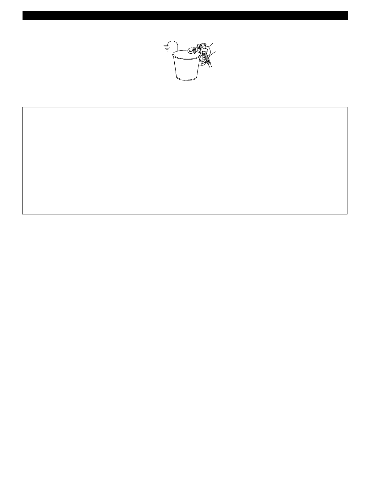
7) Caution: Static electricity can be developed by airless
spraying. Ground unit and object to be sprayed. Static
explosion can occur with ungrounded unit.
8) Flush system with spray tip removed. Always use
lowest pressure possible.
9) Always follow safety precautions and warnings printed
on paint container.
10) Only use spray guns and hoses supplied by Lemmer.
User assumes all risk and liability when using spray guns
or hoses not complying with minimum specification and
safety devices of Lemmer Spray Systems Ltd.
11) Inspect hoses before each use. Never use a damaged
hose. High pressure in hoses with wear, leaks or splits
may cause the hose to rupture and cause serious
personal injury. Never try to stop or deflect leaks with any
part of your body.
12) Use extreme caution when cleaning spray tip guard.
DO NOT try to wipe off build up around the spray tip
before following shut down procedure. Follow the Shut
down Procedure, then follow the spray tip manufacturer’s
instructions for removing and cleaning the spray tip.
13) Never attempt to change spray tip or leave the unit
unattended without first shutting off pump, releasing fluid
pressure, and locking the trigger safety lock.
14) Use extreme caution when changing spray tip. Follow
the Shut down Procedure, then follow the spray tip
manufacturer’s instructions for changing the spray tip.
ATTENTION
1) Risque d’injection de peinture: Le matériel de
pulvérisation sans air peut entraîner de graves blessures
s’il y a pénétration de la peau par la peinture. Ne jamais
pointer le pistolet vers une personne ou vers soi-même.
La garde de la buse limite le risque de blessures
accidentelles par injection mais constitue principalement
un élément de mise-en-garde. Ne jamais mettre la main,
les doigts ou toutes parties du corps contre la buse. Le
port de gants et de vêtements n'est pas nécessairement
une forme de protection non plus.Laisser le cran de sureté
du pistolet en position fermée quand il nést pas utilisé.
Toujours avoir la garde en place pour peindre.
En cas d’accident, demander immédiatement des soins médicaux.
Note au médicin: La pénétration de peinture dans la peau peut causer
de graves blessures. Il est important de traîter la blessure à la
chirurgie aussitôt possible. Ne pas retarder le traitement pour
rechercher la toxicité. La toxicité peut avoir de graves conséquences
quand certains enduits exotiques son injectés directement dans le
systéme sanguin. Une consultation avec un chirurgien spécialisant en
reconstruction de mains serait conseillable. Soyez prêts à décrire au
médecin quel liquide a été injecté.
2) Ce système peut produire une pression très élevée. Afin d’éviter des
ruptures et des blessures, ne pas utiliser ce système avec des éléments
dont la pression nominale de service est inférieure à la pression maximale
que la pompe peut atteindre (ceci s'applique, toutefois sans être limité, au
pistolet, boyau et aux raccords).
3) Ne jamais pulvériser à l’interieur un produit inflammable qui a un point
éclair inférieur à 21 degrés C,70 degrés F. L’endroit où vous peinturez doit
toujours être bien aéré. Avant de pulvériser s’assurer qu’il n’y a aucune
flamme ou pilot (veilleuse) de fournaise en marche dans l’appartement.
4) Servez-vous d’un masque respiratoire qui est certifié pour le produit que
vous pulvérisez.
5) Ne pas utiliser de solvants contenant des hydrocarbures halogénés
avec ce matériel. Il contient des particules d'aluminium et peut exploser. Les
agents de nettoyage, enduits, peintures et, adhésifs, peuvent contenir des
solvants contenant des hydrocarbures halogénés. Soyez prudents;
consultez votre fournisseur pour les informations nécessaires. (ex:
méthylène chloride and 1,1,1 - Trichloréthane)
6) Attention: La pulvérisaton d'un liquide inflammable peut entraîner un
risque d'incendie ou d'explosion, surtout dans les espaces fermés.
7) Attention: La pression du produit que l’on pulvérise peut produire une
charge électrostatique. Mettre le matériel et l'objet à pulvériser à la terre.
Des décharges d'électricité statique peuvent se produire si le matériel n'est
pas mis à la terre.
8) Retirer l'embout de pulvérisation avant de rincer le matériel tout en
utilisant une pression aussi basse que possible.
9) Toujours prendre les précautions nécessaires et observer toutes les
consignes de sécurité figurant sur le pot de peinture.
10) N'utiliser que les pulvérisateurs et les tuyaux flexibles fournis par
Lemmer. Les personnes qui utilisent des pulvérisateurs et des tuyaux
flexibles non conformes aux standards d'utilisation et de sécurité minimum
du fabricant de la pompe le font à leurs propres risques et seront les seuls
responsables.
11) Examiner soigneusement le tuyau avant de s'en servir. Il ne faut jamais
utiliser un tuyau endommagé ou avec des fentes. Un tuyau à haute pression
qui n'est pas en bon état représente un serieux danger de blessure à la
personne en cas de crevaison soudaine. Il ne faut jamais essayer d'arrêter
des fuites de liquide avec n'importe quelle partie de votre corps.
12) Il est nécessaire d'exercer beaucoup de précaution pendant le
nettoyage de la protection de la buse. Ne jamais essayer d'enlever la
peinture qui aurait pu s'accumuler sur la buse avant d'avoir suivi les
consignes de sécurité concernant le nettoyage et le remplacement de la
buse.
13) Ne jamais essayer de changer la buse ou laisser l'appareil sans surveillance
avant d'arrêter le moteur, couper la pression et verrouiller la gâchette du
pistolet.
14) Le remplacement d'une buse doit être fait avec beaucoup de
précaution. Référez-vous au PROCÉDÉ D'ENTRETIEN.
HIGH PRESSURE!
INJECTION HAZARD!

4
SAFETY PRECAUTIONS
16) Il ne faut jamais essayer de déplacer l'appareil en tirant sur le
tuyau. Il faut aussi éviter tout tortillement du tuyau.
17) Les enfants et le personnes n'ayant aucune
expérience avec ce genre de pulvérisateur doivent êtres
gardés à l'écart de l'appareil et du chantier de travail.
18) Quand on décharge des liquides inflammables il
faut utiliser des pots conducteurs en métal. Quand on
relâche la pression avec le pistolet, une partie métallique
du pistolet doit être en contact avec le pot en métal muni
de mise à la terre.
19) La protection de la gâchette réduit le risque
d'activement involontaire si on laisse tomber le pistolet ou s'il est
frappé par accident. Ne jamais utiliser le pistolet sans la
protection de gâchette.
20) Procédé à suivre avant tout travail d'entretien ou de
nettoyage.
1) Bloquer la gâchette avec le levier de verrouillage.
2) Réduire le régulateur de pression au minimum.
3) Couper l'arrivée d'air.
4) Ouvrir la vanne de mise à l'air libre pour relâcher la pression.
Gardez-la ouverte jusqu'au moment où vous êtes prêts à utiliser
l'appareil.
5) Enlever la buse.
6) Débloquer le levier de verrouillage de la gâchette.
7) Relâcher le reste de la pression en déchargeant avec le
pistolet dans un pot en métal. Quand on relâche la pression, une
partie métallique du pistolet doit être en contact avec le pot en
métal muni de mise à la terre. (Il n'est pas nécessaire d'utiliser un
pot avec mise à la terre pour des produits non inflammables,
comme par exemple le latex).
8) Ramener le levier de verrouillage en position bloquée.
16) Do not pull on hoses to move equipment, DO NOT kink or bend
the hose sharply.
17) Keep children or anyone not familiar with airless spray
systems away from equipment and work area.
18) Conductive metal containers must be used when
flushing flammable fluids through the system. Always
flush at low pressure with spray tip removed. A metal part
of the spray gun must be held firmly against the grounded
metal pail when flushing or relieving pressure from the
gun.
19) Trigger guard helps reduce the risk of accidentally
triggering the gun if dropped or bumped. Do not use a spray gun
without a trigger guard.
20) Shut Down Procedure
Always follow Shut Down Procedure before starting any
troubleshooting, servicing or cleaning.
1) Engage the trigger safety lock in the locked position. Test the
trigger safety lock to ensure the lock is working properly.
2) Turn pressure regulator to minimum.
3) Disconnect air supply.
4) Open the dump valve to relieve pressure. Leave open until
ready to spray or test or clean.
5) Remove the spray tip.
6) Disengage the trigger safety lock.
7) Trigger the gun into a metal pail to relieve any remaining
pressure. A metal part of the spray gun should be held firmly
against the grounded metal pail when relieving the pressure from
the gun. (A grounded metal pail is not required for non-flammables
such as latex.)
8) Reset the trigger safety lock to locked position.

5
PRODUCT SPECIFICATIONS
INTRODUCTION:
We appreciate your decision to purchase a Lemmer high
quality professional paint spraying system and believe
you will find it to be the best sprayer you ever owned.
Your Lemmer airless paint pump is capable of spraying a
wide variety of lacquer, some epoxies, industrial finishes,
latex, oil-based and alkyd paints, as well as stains,
preservatives and other architectural coatings. The
material you are spraying will have a direct effect on the
amount of pressure required for the optimum pattern and
coverage to be obtained. We recommend that before
actually beginning your job, you carefully read this manual
and practice with the sprayer until you feel comfortable
using it.
The Lemmer pneumatic sprayers are powerful and
versatile enough to be used in a variety of setups (pail/
cart/wall mount), and with a variety of accessories (extra
lengths of hose, extensions, pressure feed rollers, etc. as
shown on page 16.) to make them even more versatile
systems. Ask your supplier about the recommended
accessories for your particular job.
PUMP TYPE:
These units are AIR POWERED DOUBLE ACTION
PISTON PUMPS. Top quality parts keep maintenance to
a minimum. All paint valves are made of tungsten car-
bide and stainless steel for extra long abrasion resist-
ance. The advantages of this type of pump is:
- Accurate spray pattern with minimal overspray
- Minimal or no thinning of paint products
- Pumps straight out of original paint container
- Variable pressure
- Various nozzles are available for slow to fast spraying
- Quiet running & and stops when spraying stops
- Steady spraying pressure - minimal fan fluctuations
- Safe for hazardous locations - no electricity
HOW PNEUMATIC PUMPS OPERATE:
A pneumatic high pressure pump consists of a reciprocat-
ing air motor and a fluid pump. Its speed and pressure
are controled by air regulator. The pressure ratio (pump
ratio) of the high pressure pump is determined by the
square area of the air motor piston versus the square
area of the piston in the fluid pump. The pumps maximum
possible output pressure is determined by multiplying the
ratio by the compressed air pressure fed into the air
motor.
Example:
Pump ratio..................................................................14:1
Air pressure reading at air motor control................. 71 psi
Max. fluid pressure (14 x 71)................................. 995 psi
The air is connected to the air motor of the pump. First,
the pump is primed, then the pressure is set (lets say at
3000 PSI for spraying latex). When the paint pressure
reaches 3000 PSI in the hose, the paint pump parts
(including air motor) stop moving. This is the stall posi-
tion. Now, when the gun trigger is pulled and the paint
pressure begins to drop, the air motor and paint pump
immediately begin to work to maintain spraying pressure.
The results are minimal air consumption, excellent trig-
ger-paint pressure response, minimum fan fluctuations,
and minimal all-around wear!
TECHNICAL SPECIFICATIONS
max approx. air volume air motor paint pump maximum
free output max consupt'n at at max upper lower max. tip free
flow per recm'd 100 psi, at recm'd cycles piston piston piston piston size using air paint paint flow bare
pump volume cycle cycles max. recm'd cycles per dia. stroke dia. dia. suitable inlet inlet outlet volume weight
Pump model ratio gpm fl.oz. per min. cycles (cfm) gpm gallon mm mm mm mm viscosity (male) (female) (male) liter/min lbs (kg)
**”P” Series standard high pressure**
P2900 30:1 0.8 0.43 90 7 0.3 298 70 50 13 18 .019 3/8" 1/2" 1/2" BSP 2.9 15 (7)
Barrel P. 12:1 1.0 1.42 95 7 0.6 154 70 50 18 25 .035 1/2" F M36x2 1/2" BSP 4 25 (11)
**”WIWA” Series standard high ratio**
3032 32:1 0.8 0.52 85 7 0.3 248 85 42 15 21.5 .019 3/8" M12X1.0 3/8" 3.0 13 (6)
3514 14:1 0.9 0.71 70 4 0.4 179 70 43 18 25 .021 3/8" M25X1.0 3/8" 3.5 13 (6)
4032 32:1 1.1 0.92 70 11 0.5 139 85 75 15 21.5 .023 3/8" M25X1.0 3/8" 4.0 15 (7)
6034 34:1 1.6 1.24 65 15 0.6 103 105 75 18 25 .031 1/2" M25X1.0 M22X1.5 6.0 42 (19)
10018 18:1 2.6 2.44 55 13 1.0 52 105 75 25 35 .039 1/2" M25X1.0 M22X1.5 10.0 40 (18)
10032 32:1 2.6 2.44 55 23 1.0 52 140 75 25 35 .039 1/2" M25X1.0 M22X1.5 10.0 44 (20)
15042 42:1 4.0 3.85 55 47 1.7 33 200 75 31 44 .045 3/4" M25X1.0 M22X1.5 15.0 84 (38)
18066 66:1 4.8 3.90 55 75 1.7 33 200 120 25 35 .047 3/4" M35X1.5 M22X1.5 18.0 115(52)
25048 48:1 6.6 5.10 60 81 2.4 25 200 120 29 40 .061 3/4" M35X1.5 M22X1.5 25.0 126(57)
31073 73:1 8.2 7.96 50 153 3.1 16 300 120 35 50 .069 3/4" M42X1.0 1" BSP 31.0 214(97)
34020 20:1 9.0 7.65 50 42 3.0 17 200 75 44 62 .071 3/4" M25X1.0 M22X1.5 34.0 79 (36)
35032 32:1 9.2 7.96 55 75 3.4 16 200 120 35 50 .073 3/4" M42X1.0 1" BSP 35.0 132(60)
45046 46:1 11.9 12.24 45 137 4.3 10 300 120 44 62 .079 3/4" M42X1.0 1" BSP 45.0
236(107)
**High ratio barrel pumps**
2800 U 39:1 0.7 0.64 50 7 0.3 199 81.5 75 13 18 .021 3/8" N/A 3/8" 2.8
3500 U 34:1 0.9 0.78 50 7 0.3 165 81.5 75 14 20 .023 3/8" N/A 3/8" 3.5
4000 U 29:1 1.1 0.91 50 7 0.4 140 81.5 75 15 21.5 .026 3/8" N/A 3/8" 4.0

6
PUMP COMPONENTS
SPRAY GUN:
The spray gun is designed specifically for airless spray-
ing. Since there is no compressed air to atomize the
paint, atomization is accomplished by forcing the paint at
a very high pressure (3200 p.s.i) through a very small
hole (~.017" diameter). Because of this high pressure, the
spray tip and gun valve are made of tungsten carbide for
maximum wear resistance. The gun body is made of
forged alloy and anodized for chemical resistance.
As a safety feature, the spray gun can be locked with
the trigger safety lever when you are not spraying. Be
sure to read all warnings concerning the high pressures
of airless spraying on page 3&4.
AIR MOTOR
These specially designed air motors convert the energy
from compressed air into a double action stroke. Both the
up down power strokes are used by the fluid pump to
create pressure and volume. The air motors are perma-
nently greased and require minimal maintenance. Its air
source must be regulated, clean, (and oiled on larger
units)
FLUID PUMP:
The fluid pump is supplied as either of an "open" or
"closed" design.
The “
open
” design has clearly visible tie-rods which
separate the air motor and the fluid end and the travel of
the piston can be observed. In order to take full advan-
tages of the specially formulated lubricant with the “open”
design, the upper packing tightening nut has been de-
signed as a “wet-cup” to prevent fluid hardening around
the piston.
The "
closed
" version features an integrated lube
chamber with a vent hole. This lube chamber connects
between the air motor and the fluid end and the travel of
the piston may not be viewed. A specially formulated
lubricant filled into the lube chamber allows for wetting of
the upper piston on each upstroke preventing drying up or
hardening of deposits on the piston. An important aspect
of the “closed” versus “open” version is that blast grit or
any other grinding and scoring matter causing piston
damage is kept away, and the upper packings are spring
loaded to lenghten packing life.
The pump piston has approximately 0.3 mm (0.012")
layer of hard chrome to protect against wear. Both the
upper and lower ball valves have tungsten carbide seats
and stainless steel balls. Leather or Teflon “V”-packings
are installed as packing sets and arranged Leather or
Teflon “only” or alternating, i.e. “mixed”. Teflon “V”-
packings are graphite filled and the leather packings are
Thiokol impregnated.
Teflon packings are recommended when pumping
two-component materials, or coatings using strong
aggressive solvents. Leather packings are softer by
nature and flex, and thus respond better to coarse parti-
cles. A mixed packing arrangement is the best solution
for all applications.
PRESSURE REGULATOR:
The manually operated pressure regulator is on the side
of the air motor. When the handle is turned clockwise, air
pressure is increased, when the handle is turned counter-
clockwise, air pressure is reduced.
Always reduce the pressure (turn the handle all the
way counterclockwise, or disconnect air supply) when
cleaning or when switching the position of the dump valve
(if so equipped).
DUMP VALVE (IF EQUIPPED):
The dump valve is located on the side of the paint pump.
When turned to “prime” (handle in-line with body), it
circulates fluid to vent the air trapped in the paint pump
out the return hose. It will continue to recirculate the paint
until the knob is manually turned to the “spray” position.
When the dump valve is turned to “spray”, flow is shut
off through the return hose and is routed to the paint hose
for spraying.
The dump valve also serves to relieve pressure on
the system during shutdown and cleanup. The pressure is
relieved by turning the prime valve to “dump”.
COATINGS:
Nowadays almost all types of paints and coatings can be
supplied in “airless quality”. Regardless, Lemmer airless
units are available with large sized inlet filter screens, and
a high pressure filter to prevent possible plugging or
damage. In addition, gun filters and tip filters may be
supplied for extra critical painting jobs.
Viscosity alone is no measure for good pump priming,
pumpability or sprayability. It may well be that a suction
hose has to be exchanged for a straight suction tube, or
the fluid pump might be immersed into the coating to
assist the priming action.
Two-component materials generally have a short “pot
life”. The unit must be properly flused and cleaned well
before the curing time starts.
We
DO NOT
recommend pumping coarse bodied or
aggressive fluids using the airless method. These would
include sand filled wall coatings, coatings having coarse
fibres, and various types of adhesives. Damage or wear
caused to the fluid end or any other system component
by pumping or spraying any such material is not covered
by the Lemmer warranty.
Whenever in doubt, please contact Lemmer for
correct equipment selection and usage.
Fluid pump
Air motor
Air motor muffler
Wet cup
Fluid chamber
Fluid inlet
Fluid outlet
Figure 1. - Pump components 7000 P - 10032.

7
SETTING UP OF UNIT
TOOLS NEEDED:
2 x 8" or larger crescent wrench
PROCEDURE:
1) Remove all system components from the box for
assembly.
2) Remove all protective caps from inlet and outlet
connections of pump.
3) Attach suction hose or sucton pipe to inlet of pump.
Tighten securely.
4) Attach return hose or dump valve to fluid outlet fitting
to approximately 20 ft. lbs.
5) Connect high pressure airless paint hose to pump
outlet. Tighten to approximately 20 ft. lbs.
6) Attach the tip assembly to the spray gun.
7) Connect the paint hose to the swivel connection of
the spray gun. Tighten 20 ft. lbs. Ensure the gun
handle is securely hand tightened to the gun.
8) Double check all connections, the unit is now ready
for flushing.
Note: The pump contains a preservative oil when you
receive it, that may drip from the various connections
when the protective caps are removed.
WARNING: INJECTION HAZARD POSSIBLE. DO NOT
SPRAY WITHOUT TIP IN PLACE. ALWAYS ENGAGE
TRIGGER LOCK BEFORE REMOVING, REPLACING
OR CLEANING TIP. NEVER TRY TO CLEAN THE TIP
WITH YOUR FINGERS.
To disengage your trigger lock: Your spray gun is
shipped from the factory with the trigger lock in the
engaged position (horizontal on the L-45). To disen-
gage, turn the trigger lock down until it is in a vertical
position. To engage the trigger lock, turn it back to a
horizontal position.
Figure 3. - Typical wall mount system components.
pneumatic
pump.
paint return hose for
priming.
high pressure
paint filter.
attach high pressure
hose here.
dump valve for
priming.
remote suction
system.
paint suction
hose.
suction filter.
air control
assembly.
trigger lock.
Figure 2. - L-65 gun components.
gun handle
with filter
inside.
hand tight
only!
tip.
tip housing.
trigger guard
for safety. do
not remove!
high pressure
swivel, 1/4"npt.

8
ZIP TIP INFORMATION
FEATURES:
Fast Tip Size Changes - no tools required.
Long Seal Life - withstands harsh solvents - won't swell or leak - replaces in
minutes.
Tip Rotates Easily - even under “high pressure” clog-up.
Venturi-Guard - less paint accumulation - helps protect against accidental
injection and prevents tip from slipping out of position.
Patented Diffuser - safer unclogging in clean-out position.
TO OPERATE:
When tip clogs, turn zip-tip handle 180˚ to "cleanout position". Trigger gun and line
pressure will purge clog.
DO NOT spray or empty the hose in "clean out" position, this will cause
extreme wear and premature failure. Always remove the tip when cleaning
out the hose.
TO CLEAN PLUGGED TIP:
1) Rotate the tip to the “Clean” position.
2) Pull trigger and spray. This should clear the tip of any blockage.
3) Rotate the tip back to the “Spray” position and continue spraying.
4) If the clogging continues, clean or replace the gun filter and see the section in
this manual on instructions for straining and thinning paint.
Clean Position Spray Position
Figure 5. - Tip unclogging.
CAUTION: DO NOT USE A NEEDLE OR SHARP OBJECT TO CLEAN THE TIP.
TUNGSTEN CARBIDE IS BRITTLE AND CAN BE CHIPPED.
TO CHANGE ZIP TIPS:
1) Rotate zip-tip 90˚.
2) Remove from housing.
3) Install new zip tip.
4) Rotate 90˚ to spray position.
Figure 6. - Removing tip seal.
TO CHANGE SEAL ASSEMBLY:
1) Relieve line pressure and set gun safety.
2) Remove zip tip housing from gun.
3) Remove zip tip from housing.
4) Insert zip tip cylinder into front of housing and press seal assembly out of
housing.
5) Install zip tip (4) through slot in guard and into body.
6) Insert seal ass'y (2) through gun nut to seat seal around zip tip cylinder (press
firmly to insure seal is tight against cylinder).
7) Insert tip/gun washer (3) over spring (in gun nut). Install unit on gun. Tighten
gun nut.
2
1
4
Figure 4. - Zip tip
Pos. Part nos. Description
1 L043-001 Zip Tip housing with guard
L043-007 Zip Tip guard (not shown separately)
2 L043-005 Zip Tip seal kit (includes gasket #3)
L043-006 Spring, 3/pkg (not shown separately)
3 L043-008 Nylon gasket
L043-009 Tube of 8x nylon gaskets
4 L043-*** Zip Tip - see chart on opposite page
IMPORTANT: The seal ass'y (2) is a wear part
that must be replaced periodically. If leaking
occurs, replace the seal ass'y immediately
before it damages the tip (4).
FAN FAN FLOW TIP
PART NO. ORIFICE AT 1' ANGLE LTR/MIN MARKING
L043-091 .009 2" 10 DEG. 0.26 109
L043-092 .009 4" 20 DEG. 0.26 209
L043-093 .009 6" 30 DEG. 0.26 309
L043-094 .009 8" 40 DEG. 0.26 409
L043-095 .009 10" 50 DEG. 0.26 509
L043-096 .009 12" 60 DEG. 0.26 609
L043-111 .011 2" 10 DEG. 0.40 111
L043-112 .011 4" 20 DEG. 0.40 211
L043-113 .011 6" 30 DEG. 0.40 311
L043-114 .011 8" 40 DEG. 0.40 411
L043-115 .011 10" 50 DEG. 0.40 511
L043-116 .011 12" 60 DEG. 0.40 611
L043-117 .011 14" 70 DEG. 0.40 711
L043-131 .013 2" 10 DEG. 0.60 113
L043-132 .013 4" 20 DEG. 0.60 213
L043-133 .013 6" 30 DEG. 0.60 313
L043-134 .013 8" 40 DEG. 0.60 413
L043-135 .013 10" 50 DEG. 0.60 513
L043-136 .013 12" 60 DEG. 0.60 613
L043-137 .013 14" 70 DEG. 0.60 713
L043-138 .013 16" 80 DEG. 0.60 813
L043-151 .015 2" 10 DEG. 0.80 115
L043-152 .015 4" 20 DEG. 0.80 215
L043-153 .015 6" 30 DEG. 0.80 315
L043-154 .015 8" 40 DEG. 0.80 415
L043-155 .015 10" 50 DEG. 0.80 515
L043-156 .015 12" 60 DEG. 0.80 615
L043-157 .015 14" 70 DEG. 0.80 715
L043-171 .017 2" 10 DEG. 1.0 117
L043-172 .017 4" 20 DEG. 1.0 217
L043-173 .017 6" 30 DEG. 1.0 317
L043-174 .017 8" 40 DEG. 1.0 417
L043-175 .017 10" 50 DEG. 1.0 517
L043-176 .017 12" 60 DEG. 1.0 617
L043-177 .017 14" 70 DEG. 1.0 717
L043-178 .017 16" 80 DEG. 1.0 817
L043-192 .019 4" 20 DEG. 1.3 219
L043-193 .019 6" 30 DEG. 1.3 319
L043-194 .019 8" 40 DEG. 1.3 419
L043-195 .019 10" 50 DEG. 1.3 519
L043-196 .019 12" 60 DEG. 1.3 619
L043-197 .019 14" 70 DEG. 1.3 719
L043-198 .019 16" 80 DEG. 1.3 819
L043-213 .021 6" 30 DEG. 1.6 321
L043-214 .021 8" 40 DEG. 1.6 421
L043-215 .021 10" 50 DEG. 1.6 521
L043-216 .021 12" 60 DEG. 1.6 621
L043-217 .021 14" 70 DEG. 1.6 721
L043-218 .021 16" 80 DEG. 1.6 821
L043-219 .021 18" 90 DEG. 1.6 921
L043-234 .023 8" 40 DEG. 1.9 423
L043-235 .023 10" 50 DEG. 1.9 523
L043-236 .023 12" 60 DEG. 1.9 623
L043-237 .023 14" 70 DEG. 1.9 723
L043-238 .023 16" 80 DEG. 1.9 823
L043-239 .023 18" 90 DEG. 1.9 923
L043-254 .025 8" 40 DEG. 2.3 425
L043-255 .025 10" 50 DEG. 2.3 525
L043-256 .025 12" 60 DEG. 2.3 625
L043-257 .025 14" 70 DEG. 2.3 725
L043-258 .025 16" 80 DEG. 2.3 825
L043-259 .025 18" 90 DEG. 2.3 925
L043-274 .027 8" 40 DEG. 2.7 427
L043-275 .027 10" 50 DEG. 2.7 527
L043-276 .027 12" 60 DEG. 2.7 627
L043-277 .027 14" 70 DEG. 2.7 727
L043-278 .027 16" 80 DEG. 2.7 827
L043-279 .027 18" 90 DEG. 2.7 927
L043-294 .029 8" 40 DEG. 3.1 429
L043-295 .029 10" 50 DEG. 3.1 529
L043-296 .029 12" 60 DEG. 3.1 629
L043-297 .029 14" 70 DEG. 3.1 729
L043-298 .029 16" 80 DEG. 3.1 829
L043-299 .029 18" 90 DEG. 3.1 929
L043-313 .031 6" 30 DEG. 3.5 331
L043-314 .031 8" 40 DEG. 3.5 431
L043-315 .031 10" 50 DEG. 3.5 531
L043-316 .031 12" 60 DEG. 3.5 631
L043-317 .031 14" 70 DEG. 3.5 731
L043-318 .031 16" 80 DEG. 3.5 831
(larger sizes are available on request)
3

9
HOW TO SELECT TIP SIZE AND PROPER FILTER
(BASIC INFORMATION)
i
i
i
The two most important things to remember about tips.....
1) Low pressure means longer life, for tips and the pump. Less overspray too!
2) Worn tips waste paint and overwork the pump, causing premature pump wear. The maximum tip for a pump
is the largest tip that will deliver a proper pressure for spraying without overworking or overloading. When a
tip is used for some period of time, it can wear beyond the maximum size recommended for the pump, which
will cause low pressure and poor spray pattern.
• Stains and thick latex products often cause the most rapid wear of the tip, while clear lacquers and var-
nishes cause the least wear. Thus tip life can vary from as little as 50 gallons to as much as 200 or more,
depending on the product being sprayed and the pressure used.
• Filter screen mesh for the gun or pump are picked not because of the type of paint being used, but to protect
a given size of tip. Pick the tip for the type of paint and job being done and then choose the filter to protect
that tip.
Fan Size (measured at 1 foot)
Coating 2" 4" 6" 8" 10" 12"
Lacquer, varnish, furniture stain 1-09 R 2-09 R 3-09 R 4-11 R 5-11 R 6-11 R
(viscosity of 15 to 35 seconds, similar to vegetable oil)
Industrial enamels, stain, colored lacquer 1-09 R 2-11 R 3-11 R 4-13 R 5-13 R 6-15 Y
(viscosity of 25 to 50 seconds, similar to dish washing liquid)
Shop primer, solid stain, oil base, latex 1-11 R 2-13 Y 3-13 R 4-15 Y 5-15 Y 6-17 W
(viscosity of 40 to 100 seconds, similar to 10-30 motor oil)
Flat oil base, latex 1-13 Y 2-15 W 3-15 Y 4-17 W 5-17 W 6-19 W
(viscosity of 60 to 150 seconds, similar to 50 weight oil)
Thick latex, prepared blockfiller 1-15 W 2-17 W 3-17 W 4-19 W 5-19 W 6-21 *
(viscosity of 150 to 200 seconds, similar to gear oil)
Most block fillers 1-17 W 2-19 W 3-19 W 4-21 * 5-21 * 6-23 *
(viscosity of over 200 seconds, are not measurable with the Lemmer cup)
explanation of tip and filter sizing: eg:4-15 Y
4= half of fan width (8" @ 1 foot)
15 = orifice size in thousands of an inch (.015)
Y= Yellow 100 mesh filter.
(R = Red 180 mesh)
(Y = Yellow 100 mesh)
(W = White 50 mesh)
(*= *not recommended)
Tip volume at various pressures.
—Gallons per minute—
Results are based on water,
heavier viscosities will produce
less volume. This is especially
noticeable with large tips and
very heavy coatings.
TIP 500 1000 1500 2000
SIZE PSI PSI PSI PSI
.009 .039 .055 .067 .078
.011 .06 .08 .10 .12
.013 .09 .12 .15 .18
.015 .12 .16 .20 .23
.017 .16 .23 .27 .32
.019 .20 .27 .33 .39
.021 .24 .33 .41 .47
.023 .28 .40 .49 .57
.025 .33 .47 .58 .68
.027 .37 .52 .64 .76
.029 .47 .65 .79 .98
.031 .53 .75 .91 1.1
.035 .69 .9 1.0 1.2
.043 1.1 1.5 1.8 2.1
.053 1.5 2.2 2.9 3.4
.057 1.8 2.5 3.1 3.5
.063 2.2 3.1 3.9 4.4
.067 2.5 3.5 4.3 5.0
.073 2.9 4.1 5.1 5.9
.079 3.6 5.1 6.3 7.3
.085 3.9 5.5 6.7 7.8
.089 4.3 6.0 7.4 8.5
.099 5.3 7.5 9.2 10.6
Pump maximum tip size
Absolute To allow
Pump maximum for tip wear
2900 P .019 .017
6034 .031 .029
25048 .061 .059 (2X.041)
Approximate wear values comparing tungsten tips and
paint type. (Paint is in gallons)
New tip size .015 .017 .019 .027
worn to worn to worn to worn to
Tip worn to .017 .019 .021 .029
Lacquer 400 - - -
Latex 75 150 250 -
Block filler - - 75 250
Road marking paint 2 20 50 200
Tipchartexample:La-
tex stain is being
sprayed onto fencing.
Thepaint is fairly thick
(like a very heavy mo-
tor oil) and the 2900 P
isthespraypump.The
maximum tip is a .019
for a 2900 P. Draw a
linealongthe.019tips
as shown below. Eve-
rything above the line
is sprayable with the
2900 P. Now just
choose the fan width.
For fences a 6” width
willgivealotofcontrol,
sotheintersectingbest
choice would be a 3-
19 tip with a white gun
filter.
Measure the paint’s viscosity as follows: (note, paints that
are intended to be rolled should be thinned for air or airless
spraying. A general rule of thumb is 5 to 15% for latex and
oils, 30% or more for fine finishes. (consult your paint
supplier for best results).
a) Submerge the Lemmer Viscosity cup in the paint.
b) Lift the cup out of the paint and begin timing.
c) Stop timing when the steady paint stream is first broken.
d) The time recorded is the paint’s viscosity.
Notes:
ok for L-1500

10
STARTUP PROCEDURE
Whenever the pump is to be used, it must be pre-
pared for the type of paint to be used. This requires the
unit to be flushed out with an appropriate solvent (water
for latex, mineral spirits for oil base, etc.). Incorrect
flushing can cause gumming of the valves and priming
problems.
UNIT PRIMING AND FLUSHING:
1. Check that all hose, gun handle and tip connections
are tight.
2. Place trigger lock in “LOCK” position.
3. Place dump valve into open or “PRIME” position, ie:
handle pointing in-line with valve body.
4. Turn pressure regulator counterclockwise until there
is no tension. This is the MINIMUM pressure setting.
Connect air supply.
5. Place suction/return tube in correct solvent. Turn
pressure regulator clockwise until the pump begins to
cycle. DO NOT cycle fast.
6) Unit will begin pumping and solvent will flow from
return tube. Prime for about 2 minutes. If it will not
prime, try unsticking the inlet valve.
7) Turn pressure regulator back to MINIMUM. Close
dump valve, ie: “SPRAY” position, with handle
pointing out at 90°.
NOTE: ALWAYS TURN DOWN PRESSURE REGULA-
TOR BEFORE CHANGING POSITION OF THE DUMP
VALVE HANDLE. THIS REDUCES SHOCK LOADING
OF THE PUMP.
8) Turn zip tip to halfway position and remove from gun
(see page 9). Turn up pressure so that pump cycles
slowly. This gives a good low pressure for flushing
and cleaning.
9) Aim gun into empty metal pail, holding gun body
against pail edge to ground gun for safety. Open
trigger, and allow solvent to flow for one minute.
Release and lock trigger.
Read static safety on pg. 4.
10) Turn pressure control to minimum and open dump
valve to release pressure.
11) Lift both hoses above the level of solvent and turn up
pressure slightly to pump out solvent from pump.
12) Shut off unit and turn pressure regulator to minimum.
Unit is now flushed out.
PRIMING UNIT IN PAINT:
Follow same procedure as steps 1 - 8 of “Priming and
Flushing”, but instead using paint. Then continue with the
remaining steps as outlined below.
13) Remove tip from gun. Unlock trigger. Aim gun into
solvent pail and hold trigger open until solvent flow
changes to paint. Release and lock trigger. Re-
install tip.
14) Turn up pressure until about 1000 psi is reached on
the fluid outlet. If your system is not equipped with a
high pressure fluid gauge, divide 1000 (psi) by the
pump ratio to get suggested starting air pressure. ie:
1000 ÷30 (for a 30:1 ratio pump) = 33 psi input air
pressure. Test spray pattern on cardboard. Increase
or decrease pressure as required for best pattern.
Important: use lowest possible pressure which
still gives proper atomization. Excessive pres-
sures do not improve spray atomization, but will
cause excessive overspray and increased system
wear.
Figure 7. - Spray pattern examples.
TO TURN UNIT OFF:
Always reduce pressure first, then turn dump valve to
prime, trigger gun to release pressure build up in hose,
and disconnect air supply.
WARNING: DO NOT BEGIN SPRAYING BEFORE
READING THIS SECTION AND ALL PREVIOUS
SAFETY INFORMATION.
PAINTING AND TIP SELECTION:
Correct adjustment of pressure and proper tip selection
are crucial to the best spray pattern....
1) In any situation, the lowest pressure that gives an
adequate spray pattern is the best pressure to use. It
will give maximum pump and tip life and produce
minimum overspray.
2) Typically, thicker materials require larger tips and
higher pressures than thinner paints do. Some very
thick paints may require slight thinning (5-10%)
depending upon pump and tip size and application.
Generally, thinning is performed when a good spray
pattern cannot be obtained with an appropriate tip
size at maximum pressure. (see page 11).
SPRAY PAINTING METHOD:
1) Keep the gun perpendicular to the surface. Always
hold the gun perpendicular to the surface with the tip
AIRLESS SPRAYING METHODS

11
AIRLESS SPRAYING METHODS
3) Start moving the gun before triggering. To get
smooth overlap and prevent initial paint buildup, start
your stroke movement before pulling the trigger. At
the end of the stroke release the trigger before
stopping. NOTE: To assure uniform paint coverage,
overlap each stroke by 40% - 50%.
4) Intermittent use. If you are spraying and decide to
stop for several minutes, lock the spray gun trigger
and submerge the tip in a container of the appropriate
solvent. This will prevent paint from hardening in the
tiny spray opening and clogging the tip. Be sure to
release the pressure by opening dump valve and turn
off pump.
approximately 12" from the surface. If held at an
angle (up and down or side to side) paint will build up
unevenly and leave the work splotchy. (See figure 8).
2) Move with a smooth arm stroke. Move the gun at a
steady even pace while keeping the gun perpendicu-
lar to the surface. (See figure 9) Do not move the gun
by flexing your wrist. Fanning the gun will cause
excessive overspray and uneven coverage. (See
figure 10).
Figure 10. - Result of flexing wrist while spraying.
Figure 8. - Right and wrong way to hold spray gun.
PUMP:
1) Flush before each use with a solvent that is correct
for the paint you will be spraying. ie: Water for latex
paints.
2) Clean unit well after each use. A clean unit works
better and lasts longer.
(exceptions are plumbed-in
systems where the coating being pumped does not
change its state while "sitting", and where the coating
will not corrode or react with any part of the pump).
3) Flush with mineral spirits when storing the unit for
more than 3 or 4 days.
PAINT:
1) Prepare paint according to manufactuer’s recom-
mendations.
2) Remove all skins on paint.
3) Stir paint thoroughly.
4) Strain paint through a fine mesh strainer bag to avoid
clogging of pump and filters.
SPRAY TIPS:
1) Use minimum pressure that gives a good spray
pattern to reduce tip and pump wear and cut down
overspray.
2) Replace tips before they become too worn. Worn tips
waste paint and overwork the sprayer.
FILTERS:
1) Clean the filters after each use of sprayer.
2) Use correct filter for the tip size and paint type. See
chart page 11.
3) Push down on filter after inserting it into the gun
handle to test if the filter spring is at the bottom. Make
sure the filter is inserted with the double lip going into
the gun first.
PAINT HOSE:
1)
INSPECT THE HOSE PERIODICALLY. DO NOT
USE KINKED, WORN OR DAMAGED HOSE. SEE
WARNINGS ON PAGES 3 & 4!
2) Use only hose that is designed for the high pressures
of airless units. Minimum working pressure of the
maximum working pressure of the pump being used.
Be sure it is grounded, static dissipating type hose.
3) Protect both the paint hose from vehicle traffic and
sharp cutting edges or objects.
4) For best performance, maximum hose length is about
150 ft. of 1/4". This maximum will largely depend on
tip size and thickness of paint.
LUBRICATING CHAMBER OIL:
1) Check oil regularly. If it is dirty, change it. If there is
any sign of paint in the oil, tighten the upper
packings, or have them replaced at a qualified repair
shop.
2) Use only proper oil, Lemmer order number L034-
121 for one liter.
STATIC CHARGE:
THE GROUND WIRE MUST BE CONNECTED TO A
GOOD EARTH GROUND FOR PROPER SAFETY.
FAILURE TO DO THIS MAY RESULT IN A STATIC
SPARK, FIRE, PERSONAL INJURY AND PROPERTY
DAMAGE.
Figure 9. - Proper way to trigger spray gun.
HELPFUL HINTS FOR TROUBLE FREE PAINTING

12
CLEANING INSTRUCTIONS
As with all spray equipment, your spray system must
be cleaned properly or it will not operate properly.
Clogged valves and filters are the most common
causes of problems. If followed, these guidelines will
insure trouble free performance from your spray
system.
CAUTION: Clean with water if latex is used. Clean
with paint thinners for oil based paints. Both water
and paint thinner will be refered to as "solvent" from
here on in.
CLEAN-UP:
To get the best use and longest life from your spray
system, it is very important to clean it out properly. The
procedure is simple and is very similar to the flushing
procedure performed earlier. Cleaning and flushing would
also be required when changing color, or type of paint, ie:
latex changing to oil base.
1) Lock gun trigger, turn pressure regulator to minimum,
open dump valve to release all system pressure.
2) Turn zip tip to halfway position and remove from
gun. (if so equipped).
3) Lift both suction and return hose above the level of
paint in the pail and turn pressure up to a slow cycle
rate. Allow unit to pump out paint.
4) Place suction/return hose into pail with proper solvent
to flush out paint and allow unit to prime in the
solvent. Clean the outside of metal suction tube.
5) Turn pressure regulator to minimum and close
dump valve.
6) Unlock trigger, and with spray tip still removed and
starting with minimum pressure, aim gun into paint
container and hold trigger open until paint flow stops
and solvent flow just begins. Release trigger. Aim gun
into solvent pail/hopper and circulate solvent for
about two minutes. To reduce splashing, direct the
fluid stream along inside of bucket at a side angle and
well above the fluid level (or submerge the tip in the
solvent). Release trigger. Point spray gun into an
empty waste bucket and spray at least 1 gallon of
fluid into it. (see figure 13).
Warning: conductive metal containers must be used
when flushing flammable fluids through the system.
Always flush at low pressure with spray tip removed.
A metal part of the spray gun must be held firmly
against the grounded metal pail when flushing or
relieving pressure from the gun.
Figure 11. Pump fluid out.
Figure 12. Clean pump with suitable solvent .
Figure 13. Pump until clean solvent appears.
Warning!

13
CLEANING INSTRUCTIONS
7) Pump solvent out by lifting both suction and return
hose out of the solvent. Turn pressure regulator to
minimum and open dump valve to release system
pressure and disconnect air supply. Lock trigger
and clean spray tip before installing back onto gun.
8) Follow above steps 1-7 using clean solvent to
completely flush system. You may at this time, if you
wish, blow compressed air into the tip (dump valve
open and air supply disconnected) to push the
solvent all the way out the return hose.
9) If changing paint types, ie: latex (water base) to oil
base, you would have to flush system with clean
mineral spirits using above steps 1-7. This would
prepare the pump for the oil base paint. Water would
have to be used as a last flush if changing from oil
base paints to latex.
10) Ensure pressure regulator is turned to minimum
and all pressure is released. Open dump valve.
Turn pump air supply OFF.
11) Unthread gun handle from gun body to access gun
filter. Remove filter and brush clean with appropriate
solvent. Inspect filter for pinholes, plugging, or other
damage. Replace if required. Re-install with “double
lip” end pointing up into gun. Lightly grease handle
threads (petroleum jelly, auto grease) and re-install
firm hand tight. Brush exterior of gun clean.
12) Remove intake screen on metal suction tube and
brush clean, re-install.
13) Storing unit for more than 3 days. If system was
cleaned with an oily paint thinner such as varsol, it is
now ready for storage (after step 14). If system was
cleaned with water or a strong thinner (ie. lacquer
thinner) pump varsol (or mineral spirits) through the
entire system by repeating step 8. If varsol is not
available, drain all the solvent out of the hose, gun,
and pump. (Tungsten carbide parts in the valves
will corrode if left in water for long periods of
time). With the pump running in the prime mode,
place the inlet valve in a container of light oil. Let the
pump run until it spits oil drops out the return fittings.
This will displace any remaining solvent and lubricate
the valves for storage.
14) Coil up spray hose, inspecting for signs of damage.
Suggested minimum coil size for 1/4" paint hose is 18
inches.
DO NOT COIL PAINT HOSE TOO TIGHTLY. THIS MAY
CAUSE KINKS, WHICH WEAKEN THE HOSE. A
PAINT HOSE WITH KINKS OR OTHER DAMAGE
SHOULD BE CONSIDERED UNSAFE AND BE RE-
PLACED IMMEDIATELY.
WARNING: DO NOT CLEAN THE SPRAY GUN UN-
LESS THE PRESSURE HAS BEEN RELEASED FROM
THE SYSTEM. SEE PAGES 3 & 4 FOR FURTHER
PRECAUTIONS.
Figure 14. Fluid is pumped out.

14
ACCESSORIES FOR LEMMER AIRLESS EQUIPMENT
STRAINER BAGS
1 Gallon strainer bag w/elastic ........ L034-208
5 Gallon strainer bag w/elastic ........ L034-209
COTTON OVERALLS & STIR RODS
Small overalls..................................L034-220
Medium overalls ..............................L034-221
Large overalls .................................L034-222
Extra large overalls .........................L034-223
1 Gal stir rod (2-3/8" dia.,3/8"chuck) .... L034-050
1 Gal stir rod (3-1/4" dia.,3/8"chuck) .... L034-051
5 Gal stir rod (4-3/4" dia.,1/2"chuck) .... L034-052
SPRAY HOODS
Spray hoods (package of 3)............L034-205
RESPIRATOR
North respirator (complete) .............L034-200
PIPE COATING “HOLLOW CONE” TIP
Pipe coating tip, state size .............. L033-5**
TIP CLEANING BROACH
Package of 12X...............................L033-021
TIP EXTENSIONS
1/4 Meter extension with swivel ......L033-024
1/2 Meter extension with swivel ......L033-025
1 Meter extension with swivel .........L033-026
2 Meter extension with swivel .........L033-027
POLE GUNS
3' Pole gun W/O tip assembly .........L033-050
6' Pole gun W/O tip assembly .........L033-051
TELESCOPIC PRESSURE FEED ROLLER
Telescopic roller ..............................L012-002
3/8 X 12" cover................................ L012-503
1/2 X 12" cover................................ L012-504
3/4 X 12" cover................................ L012-505
1-1/4 X 12" cover ............................L012-506
End cap kit ......................................L012-508
GAUGE KIT
General use, 1/4" connections ........L034-104
GUN FILTERS (for the L-45, L-50, & L-60)
Gun filter kit (5 X red & 1 X spring) .L032-100
Gun filter kit (5 X yellow& 1 X spg) . L032-101
Gun filter kit (5 X white& 1 X sprg) .. L032-102
FIBRE BRAID AIRLESS HOSE
1/4" X 25' Hose ...............................L031-073
1/4" X 50' Hose ...............................L031-074
STEEL BRAID AIRLESS HOSE
3/16" X 3' Whip hose.......................L031-010
3/16" X 5' Whip hose.......................L031-011
3/16" X 25' Hose .............................L031-012
3/16" X 50' Hose .............................L031-013
1/4" X 5' Whip hose.........................L031-020
1/4" X 25' Hose ...............................L031-021
1/4" X 50' Hose ...............................L031-022
1/4" X 100' Hose .............................L031-023
HOSE CONNECTORS
1/4"m X 1/4"m .................................L035-001
3/8"m X 3/8"m .................................L035-002
1/4"m X 3/8"m .................................L035-005
“SF” SUPER FINE FINISHING TIP
SF tip, state size ............................. L044-***
Standard tip nut...............................L032-501
Nylon gasket for standard tip ..........L043-008

15
OTHER QUALITY LEMMER PRODUCTS
LEMMER'S Full line of equipment comes with FIRST CLASS SERVICE in numerous
locations across CANADA, and a FULL ONE YEAR WARRANTY. For information on choosing the
right sprayer for your job, please contact your nearest LEMMER outlet.
AIR GUNS & PRESSURE POTS
Conventional air spray guns for fine
finishing. Suitable for countless industrial
and automotive applications. Available in
suction, gravity, and pressure feed
versions. Each is available in many
different needle sizes.
LINEMARKERS
Designed to handle the abrasive nature
of road marking paint. There are three
sizes of walk-behinds, and some are
available with two or more guns. Custom
systems are also made to order depend-
ing on the requirements.
HVLP TURBINE & VENTURI UNITS
High Volume Low Pressure sprayers are
used for fine finishing where overspray
must be kept to a minimum. The finish
results are equal to or better than
conventional air spray. The turbine
systems are self contained and do not
require an outside air source. The
VENTURI spray gun only uses about 8
CFM of shop air. Applications vary from
automotive finishing to commercial multi-
color architectural coating.
ELECTROSTATIC UNITS
The electrostatic WRAP-A-ROUND
charge makes this the best method of
spraying metal with next to no overspray.
It is best suited for industrial paints with
an aromatic thinner base, i.e: toluol, xylol.
The conversion kit will hook up to most
airless pumps and we carry a completely
self contained portable system.
GAS DIAPHRAGM
These sprayers are the same as the
electric diaphragm pumps, but with the
advantage of a gas engine. All use
Honda motors and belt drive systems.
AUTOMATIC GUNS
Suitable for all heavy duty airless applica-
tions. Air actuated, universal rod mount-
ing, and standard 1/4" NPS hose connec-
tion.
ELECTRIC DIAPHRAGM
These sprayers are the same as above
piston pumps except in a lower cost
diaphragm design. The motor runs
continuous for the ultimate spraying
pressure control. Hopper models are
easiest to clean.
ELECTRIC PISTON PUMPS
Commercial airless sprayers for all sizes
of jobs and spraying a large variety of
paint types. These units are portable and
come in many different performance
categories. There are small units for
spraying a house or barn once a year,
and large units for spraying warehouses
on a continuous basis.
PAINTING SUNDRIES
Overalls, strainer bags, stir rods, etc. A
large variety of painting accessories to
help make a cleaner and more efficient
working environment.
AIRLESS ACCESSORIES
A very large assortment of hoses, guns,
tips, and filters, etc. These items are
universal to most airless spray equipment
on the market.
ELECTRIC CUP GUNS
Hand held airless sprayers to spray all
standard paints. They are suitable for
large jobs where time is not a factor, and
also for the professional to touch up after
the large equipment is finished.
PNEUMATIC PISTON PUMPS
Being an air powered airless, these units
are generally used for industrial coatings.
Applications range from portable lacquer-
ing to plumbed-in automatic systems.
Also excellent for industry where operat-
ing conditions are very demanding.
TRANSFER PUMP
It can be used to transfer paint to remote
locations, or directly to high pressure
pumps. At a 1:1 ratio with up to 125 PSI
air pressure it can also supply numerous
air guns.

16
TROUBLESHOOTING
Provided you have followed the instructions, the spray system will operate efficiently and give trouble-free
service.Should any unexpected problem arise you can, in most cases, remedy the problem by following the chart
below. If you find that you cannot correct the problem, then take the sprayer to your nearest authorized service agency.
Many of the “causes” listed are unlikely to happen. However, all are included in an attempt to cover every possibility.
IT IS ABSOLUTELY ESSENTIAL FOR TROUBLE-FREE OPERATION THAT YOUR AIRLESS SPRAY SYSTEM BE
KEPT CLEAN AND FREE OF RESIDUAL PAINT BUILD-UP ON THE INTERNAL PARTS. IT MUST BE CLEANED
AND LUBRICATED AFTER EVERY USE.
Cause
1) Air supply is not connected.
2) Dump valve is not open.
3) Jammed air motor. (not frosted).
4) Jammed air motor. (frosted).
5) Jammed fluid end.
(improper cleaning).
1) No fluid or suction tube not totally
immersed in fluid.
2) Suction filter clogged.
3) Suction tube loose at inlet valve.
4) Inlet valve stuck or dirty.
5) Shaft valve stuck or dirty.
6) Outlet fitting (back pressure valve)
plugged.
7) Dump valve (prime valve) plugged.
8) Packings and/or valves worn.
1) Inlet valve stuck or dirty or worn.
1) Shaft valve stuck or dirty or worn.
2) Lower packings worn.
3) Lower piston/cylinder worn.
1) Inlet and shaft valve stuck or dirty or
worn.
2) Packings worn.
3) Pump piston worn.
4) Dump valve worn.
5) Fluid leak somewhere in system.
Remedy
1) Turn on.
2) Open (handle inline with valve body).
3) Shift air motor shifter manually to help
identifiy problem.
4a) Reduce air pressure, use smaller tip.
4b) Install air filter to remove water.
4c) Replace oil in air lubricator with radiator
antifreeze (only for as long as neccessary).
5) Disassemble and clean.
1) Add more fluid or immerse suction tube in
fluid.
2) Clean or replace filter.
3) Clean connection and tighten.
4) Unstick valve ball with blunt object (pencil).
If this doesn’t work remove valve and give it
a good cleaning.
5) Remove inlet valve to inspect shaft valve.
Unstick shaft valve ball with blunt object
(pencil). If this doesn’t work remove valve
and give it a good cleaning.
6) Clean.
7) Take valve off and clean it.
8) Overhaul pump fluid end.
1) Clean or replace.
2) Replace pump packings.
3) Replace.
1) Clean or replace.
2) Replace pump packings.
3) Replace.
4) Replace valve.
5) Check all connections and components.
Problem
I Pump does not
cycle.
II Pump cycles but
does not draw up
fluid.
III Pump pressurizes
fluid but single
strokes. (holds
pressure on up
stroke with air
motor shifter in
down position).
III Pump pressurizes
fluid but single
strokes. (holds
pressure on down
stroke with air
motor shifter in up
position).
III Pump pressurizes
fluid but does not
stop cycling.
(does not hold
pressure on either
stroke).

17
TROUBLESHOOTING
Remedy
1) Increase air supply volume.
2) Select smaller tip or try newer tip.
3) Clean or replace filter.
4) Clean or replace, daily. Keep extra filters on
hand.
5) Use correct filter OR strain/thin paint.
6) Clean connection thoroughly and tighten.
7) Thin or strain paint.
8) Replace valve.
9) See problems III, IV, & V to pinpoint.
10) Overhaul air motor.
1) Increase air regulator pressure setting.
2) Clean connection thoroughly and tighten.
3) Clean or replace valve.
4) Replace valve.
5) See problems III, IV, & V to pinpoint.
1) Tighten adjusting nut. (where applicable).
2) Replace pump fluid end packings.
1) Disassemble and clean.
2) Replace.
3) Adjust rear tension nut. If this doesn’t work
examine ball and replace if necessary.
Replace of adjust (where applicable).
Clean spray tip. Clean or replace gun filter.
Clean or replace gun filter. Clean spray tip.
Cause
1) Insufficient air supply.
2) Spray tip hole too large, either wrong
size or worn.
3) Suction filter clogged.
4) Gun filter or h.p. filter plugged.
5) Gun filter too fine for coarse paint
being sprayed.
6) Suction tube not firmly tightened to
inlet valve.
7) Paint too heavy or coarse.
8) Leaky dump valve.
9) Valves and/or packings dirty or worn.
10) Air motor worn (air hissing sounds).
1) Pump pressure too low.
2) Leaky suction tube at inlet valve.
3) Leaky or dirty dump valve.
4) Leaky, worn, or damaged inlet valve.
5) Valves and/or packings dirty or worn.
1) Upper packings loose.
2) Worn upper packings.
1) Foreign matter or paint buildup
between ball and seat.
2) Worn ball or seat.
3) Ball not in correct position.
Worn packing
Spray tip or gun filter plugged.
Partially plugged spray tip or filter.
Problem
IV Sprayer draws up
paint, pressure
builds up, but
drops away mark-
edly when gun is
opened (low
performance).
V Pressure/spray fan
fluctuation.
VI Paint in oil cham-
ber (at upper
packings).
VII Spray gun won’t
shut off.
VIII Spray gun leaks.
IX Spray gun won’t
spray.
X Low paint output
from spray gun.
NOTE: When dump valve is in “spray” position and you are getting
flow back through the return tube, remove the dump valve and
repair or replace.
Hint...
to get maximum use out of the dump valve:
a) Always reduce pressure before turning the handle.
b) Turn the handle with a continuous solid movement. (Do not turn
slowly or leave it partially open or closed).
NOTE: The air motor should always be fed clean, dry and oiled air.
If system does not have an oiler, squeeze wheel bearing
grease into air inlet of motor once or twice per year.

18
L-65 PARTS LIST & DIAGRAM
Apr99
Pos. Part nos. Description Qty.
L032-030 L-65 airless gun without tip nut
L032-035 L-65 airless gun without tip nut (G-thread)
1 L032-501 Tip retainer (11/16" L-thread) opt.
L032-710 Tip retainer (7/8" G-thread) opt.
2 tip (see separate list) opt.
3 L043-008 Nylon washer 1
4 L032-711 Seat, (11/16" L-thread) 1
L032-712 Seat, (7/8" G-thread) 1
5 L032-589 Trigger guard 1
6 L032-523 Trigger pin 1
7 L032-713 Trigger complete 1
8 L032-714 Gun body 1
9 L032-591 Pin 2
10 L032-715 Ball with shaft 1
11 L032-507 Wedge 1
12 L032-508 Packing 1
13 L032-716 Housing 1
14 L032-582 Spring shaft 1
15 L032-588 Spring 1
16 L032-583 Housing nut 1
17 L032-587 Retainer cap 1
18 L032-590 Lock nut 1
19 L032-514 Handle seal 1
20 L032-516 Gun filter, white (50 mesh) 1
L032-517 Gun filter, yellow (100 mesh) opt.
L032-518 Gun filter, red (200 mesh) opt.
21 L032-519 Filter spring 1
22 L032-717 Handle 1
23 L032-520 Copper seal 1
24 L032-521 Swivel, 1/4" nps 1
Accessories:
L032-718 Repair kit, L-65-L (#4,10,12,14,18)
L032-719 Repair kit, L-65-G (#4,10,12,14,18)
Pos. Part nos. Description Qty.
Turning this
nut tightens the
packing. Check
occationally and do
not over tighten.
HIGH PRESSURE!
INJECTION HAZARD!
Specifications, L-65
Maximum pressure: 3600 psi.
Tip thread: 11/16-16 or 7/8-14.
Hose connection: 1/4" nps.
Wetted parts: Al,SS,TC,Cu,
Brass,Tef.
Important
To engage trigger
safety lock, turn
lever tab to horizon-
tal position. Test
regularily for proper
functioning while
system is shut
down.
(trigger shown in horizontal
locked position)
locked
unlocked
• Remove filter for cleaning, then reinstall and hand tighten the handle.
• To clean gun: flush the inside by spraying proper solvent, and wipe the
exterior. (It is not neccessary to disassemble gun components under normal
circumstances).
• Follow shut down procedure before
servicing or cleaning equipment. (see #1
overleaf)
•This instruction sheet is only a supplement to
your system operating instructions. Read your
system manual before operating any high
pressure equipment.
Procedure, then follow the spray tip manufacturer’s instructions for removing and cleaning the
spray tip.
• Never attempt to change spray tip or leave the unit unattended without first shutting off
pump, releasing fluid pressure, and locking the trigger safety lock.
• Conductive metal containers must be used when flushing flammable fluids through
the system. Always flush at low pressure with spray tip removed. A metal part of the spray
gun must be held firmly against the grounded metal pail when flushing or relieving pressure
from the gun.
•Trigger guard helps reduce the risk of accidentally triggering the gun if dropped or bumped.
Do not use a spray gun without a trigger guard.
16
17 18
15
14*
13
12
19
11
24
23
22
21
6
7
8
5
4
3
2
9
1
10*
20
9
Important: this "double lip" end
of filter must go in the gun first.
o
• Injection hazard: Airless Painting Equipment can cause serious injury if the spray
penetrates the skin. Do not point the gun at anyone or any part of the body. The tip guard
provides some protection against accidental injection injuries, but is mostly a warning
device. Never put your hand, fingers or body over the spray tip. Gloves and clothing do not
necessarily offer any protection either. Keep the gun trigger safety lever in locked postion
when not spraying. Always have the tip guard in place while spraying.
In case of penetration seek medical aid immediately!
Note to physician
: Injection
into skin is a serious traumatic injury. It is important to treat the injury surgically as
soon as possible. Do not delay treatment to research toxicity. Toxicity is a concern
with some exotic coatings injected into the bloodstream. Consultation with a plastic
surgeon or reconstructive hand surgeon may be advisable. Be prepared to tell the
doctor what fluid was injected.
• Do not use halogenated hydrocarbon solvents in this system; it contains aluminium
parts and may explode. Cleaning agents, coatings, paints, and adhesives may contain
halogenated hydrocarbon solvents. Don't take chances, consult your material supplier to be
sure. (ex: methylene chloride and 1,1,1 - Trichlorethane)
• Caution: When a flammable liquid is sprayed there may be danger of fire or explosion
especially in a closed area.
• Use extreme caution when cleaning spray tip guard. DO NOT try to wipe off build up
around the spray tip before following shut down procedure. Follow the Shut down
* note: once #10
& #14 are
assembled, the
length from end
to end must be
88 - 88.5 mm.

19
L-65 SPRAY GUN OVERHAUL
Use diagram on opposite side for reference.
Tools needed:
10 mm socket and driver
2 x 8" or larger crescent wrench
1 x L-65 repair kit
Cleaning brush and lacquer thinner
needle nose pliers
1) Initiate shut down procedure:
Shut Down Procedure: Always follow Shut Down Procedure before starting any
troubleshooting, servicing or cleaning.
1) Engage the trigger safety lock in the locked position. Test the trigger safety lock to ensure
the lock is working properly.
2) Turn pressure regulator to minimum.
3) Disconnect electric plug from wall socket, or disconnect air supply.
4) Open the dump valve to relieve pressure. Leave open until ready to spray or test or clean.
5) Remove the spray tip.
6) Disengage the trigger safety lock.
7) Trigger the gun into a metal pail to relieve any remaining pressure. A metal part of the
spray gun should be held firmly against the grounded metal pail when relieving the
pressure from the gun. (A grounded metal pail is not required for non-flammables such as
latex.)
8) Reset the trigger safety lock to locked position.
2) Using the two crescent wrenches, disconnect the gun and gun handle from spray hose.
3) Remove spray tip or attachment assembly from gun.
4) Hold gun trigger open and remove seat (#4) from gun. Release trigger. Never remove or
attach seat unless trigger is held in the open position. Permanent and expensive
damage to both ball and seat will result!
5) Using 10mm socket and driver, remove adjusting nut (#18) from rear of gun.
6) Grasp retainer cap (#17) and pull away from rear of gun. Remove the two trigger pins (#9)
from gun.
7) The ball spring assembly can be removed from the rear of the gun body by unthreading six to
eight turns and then pulling firmly towards rear of gun body (#13). Push packing & wedge
(#11&12) out of rear of gun body.
8) Remove gun handle from gun and remove filter and filter spring.
9) Using points of needle nose pliers, unscrew housing nut (#16) from housing (#13). Grasp end
of shaft (#14) and remove. Take spring (#15) off of shaft for cleaning.
10) If the ball (#10) has a groove worn in it, the ball with shaft will have to be replaced. Usually the
seat will have to be replaced as well, as it wears against the ball. Both of these parts are
included in the repair kit.
11) Lightly grease wedge & packing & assemble together. Install wedge first, and then the packing
into gun body until they bottom.
12) Lightly grease spring & outside of housing. Install spring on spring shaft, and put into housing.
Install housing nut & tighten until flush with rear face of housing.
13) Thread housing into rear of gun body. Tighten to a maximum of 3-5 ft/lbs.
14) Examine the trigger pins for wear and equal length. Lightly grease and install.
15) Install retainer cap on rear of gun and install locking nut. Tighten locking nut until approxi-
mately two threads show out rear of the nut.
16) Thread gun handle into gun body and hand tighten.
17) Lightly grease threads of seat. Install trigger guard over open end of seat. Hold gun trigger in
open position and install seat. Tighten to 30-40 ft. lbs. and release trigger.
18) The retainer cap should have a bit of slack in it and should not be bottomed against the gun
tightly. The trigger should have 3/8" slack at the bottom of the trigger before engaging against
the trigger pins.
This slack is very important for the correct operation of your gun. The gun and safety lock will
not work properly if this step is not performed correctly.
To increase slack, loosen the locknut a little and test slack again.
To decrease slack, tighten the locknut a little and test slack again.
With too much slack, the gun may not turn on, but the safety lock will work fine. With too little
or no slack, the gun may be permanently ON and the safety lock does nothing.
DO NOT RUSH OR IGNORE THIS STEP, CORRECT OPERATION OF THE SAFETY
TRIGGER LOCK REQUIRES PROPER ADJUSTMENT OF TRIGGER SLACK.
19) Install tip attachment onto gun. Remove gun handle, install spring and filter, lightly grease
threads and re-install.
20) Place trigger in LOCK position. Install gun to hose, tightening securely. Install tip where
applicable. The gun is now ready for testing and use.
L-50 & L-50N GUN
May99
HIGH PRESSURE!
INJECTION HAZARD!
Pos. Part nos. Description Qty.
14 L032-536 Tension knob 1
L032-566 Tension knob (L50N) 1
15 L032-514 Handle seal 1
16 L032-516 Gun filter, white (50 mesh) 1
L032-517 Gun filter, yellow (100 mesh) opt.
L032-518 Gun filter, red (200 mesh) opt.
17 L032-519 Filter spring 1
18 L032-529 Handle, blue 1
19 L032-520 Copper seal 1
20 L032-521 Swivel, 1/4" nps 1
21 L032-537 Trigger complete 1
22 L032-523 Trigger pin 1
Accessories:
23 L032-560 Wrench, general use opt.
24 L032-538 Wrench, L-35/L-50 for nut #12 opt.
L032-595 Repair kit (Incl. pos. 4,6,8,9,12,15)
7
10
13
14
16
17
18
19
21
22
12
9
8
11
15
20
123
4
56
To identify version, note hook on housing (7)
L-50 version:
no hook
L-50N version:
has hook
Specifications, L-50
Maximum pressure: 5800 psi.
Tip thread: 11/16 - 16.
Hose connection: 1/4" nps.
Wetted parts: Al,SS,TC,Cu,
Brass,Tef.
Important
To engage trigger
safety lock, turn
lever tab to horizon-
tal position. Test
regularily for proper
functioning while
system is shut
down.
(trigger shown in horizontal
locked position)
locked
unlocked
Important
this "double lip"
end of filter
must go in gun
first.
n
24
23
Pos. Part nos. Description Qty.
L032-009 L-50 airless gun without tip nut
L032-010 L-50 airless gun with tip nut
1 L032-501 Tip retainer opt.
2 tip (see separate list) opt.
3 L043-008 Nylon washer opt.
4 L032-503 Seat 1
5 L032-589 Trigger guard (L-45, L-50N) 1
L032-530 Trigger guard with hook (L-50) 1
6 L032-531 Ball with shaft 1
7 L032-532 Gun body (L-50) 1
L032-528 Gun body (L-50N) 1
8 L032-507 Wedge 1
9 L032-508 Packing 1
10 L032-533 Packing nut 1
11 L032-534 Drum (L-50) 1
L032-527 Drum with pin (L-50N) 1
12 L032-511 Nut 1
13 L032-535 Spring 1

20
SPRAY SYSTEMS LTD.
(specifications are subject to change without notice)
(caractéristiques sont sujets à changement sans prévis)
LEMMER PAINT SPRAYING EQUIPMENT LIMITED WARRANTY
LEMMER Spray Systems Ltd. extends to the original purchaser of its paint spray equipment a limited one year warranty from the date
of purchase against defects in material or workmanship provided that the equipment is installed and operated in accordance with the
recommendations and instructions written in the owners manual. LEMMER Spray Systems Ltd. will repair or replace, at its option,
defective parts without charge if such parts are returned (still intact in the original equipment) with transportation charges prepaid to the
nearest LEMMER Spray Systems Ltd. outlet. An original proof of purchase must be attached.
THIS WARRANTY DOES NOT COVER:
Normal wear and/or defects caused by or related to abrasion, corrosion, abuse, negligence, accident, faulty installation or tampering in
a manner which impairs normal operation.
Transportation costs and other incidental, direct, special, or consequential damages or loss.
DISTRIBUTION CENTRES ACROSS CANADA
• SALES • SERVICE • PARTS •
www.lemmer.com
CALGARY Lemmer Spray Systems Ltd.
(head office) 4624 - 12th Street N.E. Calgary, AB, T2E 4R4
TEL: (403) 250-7735 FAX: (403) 291-9095
TORONTO Lemmer Spray Systems (Ont.) Ltd.
7585 Torbram Rd, #7&8, Mississauga, ON, L4T 1H2
TEL: (905) 673-1555 FAX: (905) 673-3201
MONTRÉAL Lemmer (Qué.) Inc.
2851 Bd le Corbusier, Chomedey, Laval, QC, H7L 4J5
TEL: (450) 681-8220 FAX: (450) 681-4914
Jul-22-16
manual #L280-595
This manual suits for next models
13
Table of contents
Other Lemmer Water Pump manuals
Popular Water Pump manuals by other brands

Little Giant
Little Giant 1-AA-MD installation manual

Zoeller
Zoeller AqyaNot 508 Active installation instructions

Tunze
Tunze silence 1073.008 Instructions for use

PowerWise
PowerWise 4061 Service & operating manual

red lion
red lion 2RLAG-1L owner's manual

Homa
Homa Barracuda GRP Series Installation and operation instruction manual