manuals.online logo
Brands
  1. Home
  2. •
  3. Brands
  4. •
  5. Lennox
  6. •
  7. Air Conditioner
  8. •
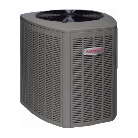
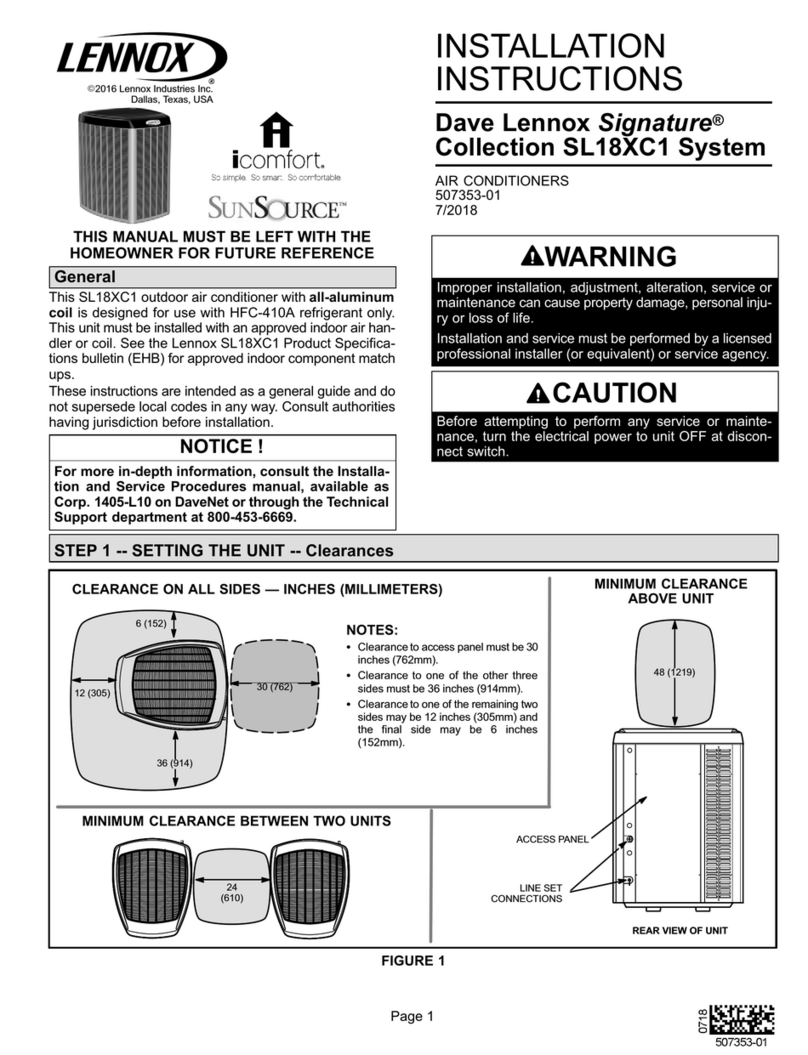
  9. Lennox SPA036H4 User manual

Lennox SPA036H4 User manual

This manual suits for next models

2

Other Lennox Air Conditioner manuals

Lennox CB29M User manual

Lennox

Lennox CB29M User manual

Lennox WING User guide

Lennox

Lennox WING User guide

Lennox AC13 -018 User manual

Lennox

Lennox AC13 -018 User manual

Lennox XC25-024-230-01 Manual

Lennox

Lennox XC25-024-230-01 Manual

Lennox 2SCU13-18 User manual

Lennox

Lennox 2SCU13-18 User manual

Lennox LGT036 User manual

Lennox

Lennox LGT036 User manual

Lennox 13ACX Manual

Lennox

Lennox 13ACX Manual

Lennox LM012CI-100P432-1 User manual

Lennox

Lennox LM012CI-100P432-1 User manual

Lennox MCA Series User manual

Lennox

Lennox MCA Series User manual

Lennox MPA012S4S-1L User manual

Lennox

Lennox MPA012S4S-1L User manual

Lennox Comfort Series User manual

Lennox

Lennox Comfort Series User manual

Lennox Comfair HC User manual

Lennox

Lennox Comfair HC User manual

Lennox XC21 User manual

Lennox

Lennox XC21 User manual

Lennox KG 024 Guide

Lennox

Lennox KG 024 Guide

Lennox CBX32MV-018/024 User manual

Lennox

Lennox CBX32MV-018/024 User manual

Lennox VERDB01C432P User manual

Lennox

Lennox VERDB01C432P User manual

Lennox LGM036 User manual

Lennox

Lennox LGM036 User manual

Lennox CBX25UH-018 Manual

Lennox

Lennox CBX25UH-018 Manual

Lennox Quantum Waterside LQWFC 150 User manual

Lennox

Lennox Quantum Waterside LQWFC 150 User manual

Lennox LM012CI-100V433 User manual

Lennox

Lennox LM012CI-100V433 User manual

Lennox FLEXY FC 050 Series User manual

Lennox

Lennox FLEXY FC 050 Series User manual

Lennox EL16XC1-018-230 User manual

Lennox

Lennox EL16XC1-018-230 User manual

Lennox LM018CI-115P432-1X User manual

Lennox

Lennox LM018CI-115P432-1X User manual

Lennox 10ACE Series User manual

Lennox

Lennox 10ACE Series User manual

Popular Air Conditioner manuals by other brands

Fujitsu ASYG 09 LLCA installation manual

Fujitsu

Fujitsu ASYG 09 LLCA installation manual

York HVHC 07-12DS Installation & owner's manual

York

York HVHC 07-12DS Installation & owner's manual

Carrier Fan Coil 42B Installation, operation and maintenance manual

Carrier

Carrier Fan Coil 42B Installation, operation and maintenance manual

intensity IDUFCI60KC-3 installation manual

intensity

intensity IDUFCI60KC-3 installation manual

Frigidaire FAC064K7A2 Factory parts catalog

Frigidaire

Frigidaire FAC064K7A2 Factory parts catalog

Sanyo KS2432 instruction manual

Sanyo

Sanyo KS2432 instruction manual

LG MultiV Series installation manual

LG

LG MultiV Series installation manual

CLIMAVENETA a-CHD U-2T 606+2209 OPERATING AND INSTALLATION Manual

CLIMAVENETA

CLIMAVENETA a-CHD U-2T 606+2209 OPERATING AND INSTALLATION Manual

Midea EWK06CW5 user manual

Midea

Midea EWK06CW5 user manual

Pioneer FAB Series installation manual

Pioneer

Pioneer FAB Series installation manual

SPT WA-1511S user manual

SPT

SPT WA-1511S user manual

Mitsubishi Electric Mr.Slim MSZ-A24NA operating instructions

Mitsubishi Electric

Mitsubishi Electric Mr.Slim MSZ-A24NA operating instructions

Mitsubishi Electric PUHZ-RP50VHA4 Service manual

Mitsubishi Electric

Mitsubishi Electric PUHZ-RP50VHA4 Service manual

Panasonic CS-S18HKQ Service manual

Panasonic

Panasonic CS-S18HKQ Service manual

Panasonic CS-E15NKE3 operating instructions

Panasonic

Panasonic CS-E15NKE3 operating instructions

Gree GWH18TC-K3DNA1B/I Service manual

Gree

Gree GWH18TC-K3DNA1B/I Service manual

Friedrich ZoneAire Compact P08SA owner's manual

Friedrich

Friedrich ZoneAire Compact P08SA owner's manual

Daikin R32 Split Series installation manual

Daikin

Daikin R32 Split Series installation manual

manuals.online logo
manuals.online logoBrands
  • About & Mission
  • Contact us
  • Privacy Policy
  • Terms and Conditions

Copyright 2025 Manuals.Online. All Rights Reserved.

,t_2006 Lennox industries Inc,
Dallas, Texas, USA
WARNING
AIMPORTANT
CAUTION
INSTALLATION
INSTRUCTIONS
SPA Units
SPA036H4 (3 Ton)
SPA048H4 (4 Ton)
SPA060H4 (5 Ton)
S-CLASS " HEAT PUMP UNITS
504,867M
06/06
Supersedes 03/06
)puTeChnical
blications
Litho U.S.A.
SPA Outdoor Unit ............................. 1
Shipping and Packing List ...................... 1
General Information ........................... 1
Unit Dimensions ............................... 2
Parts Arrangement ............................ 2
Setting the Unit ............................... 3
Electrical ..................................... 4
Refrigerant Piping ............................. 6
Refrigerant Metering Device .................... 8
Flushing Existing Line Set & Indoor Coil .......... 8
Manifold Gauge Set ........................... 10
Service Valves ................................ 10
Leak Testing .................................. 11
Evacuation ................................... 12
Start-Up ...................................... 12
Refrigerant Charging ........................... 13
System Operation ............................. 16
Defrost System ............................... 17
Maintenance .................................. 18
Optional Accessories .......................... 18
Start-Up and Performance Check List ............ 20
RETAIN THESE INSTRUCTIONS
FOR FUTURE REFERENCE
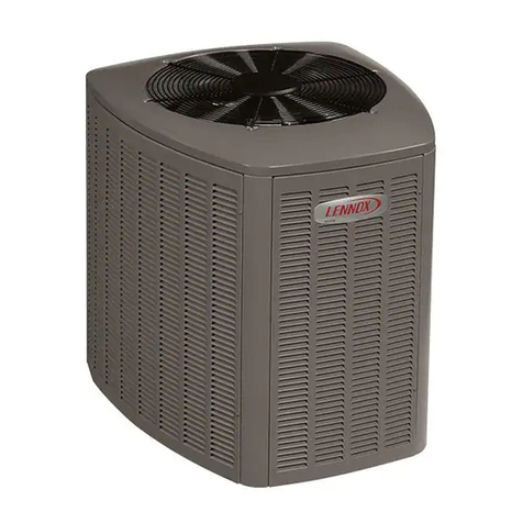
The S-Class '" SPA outdoor units use R-410A HFC refrig-
erant. This unit must be installed with a matching indoor
coil and line set as outlined in the Lennox Engineering
Handbook. SPA outdoor units are designed for use in ex-
pansion valve (TXV) systems only. They are not designed
to be used with other refrigerant flow control devices. The
Lennox Engineering Handbook lists indoor TXV kits that
must be ordered separately.
These instructions are intended as a general guide and do
not supersede local codes in any way. Consult authorities
who have jurisdiction before installation.
Assembled SPA outdoor unit
Grommets (for liquid and vapor lines)
Check equipment for shipping damage. If you find any
damage, immediately contact the last carrier.
06/06
IIIIIIIIIIIIIIIIIIIIIIIIIIIIHIIIIIIII Page 1 504,867M
IIIIIIIIIIIIIIIIIIIIIIIIIIIIIIIIIIIIIIIIIIIIIIIIII
Model
Dimen-
sion SPA036 SPA048/060
Inches mm Inches mm
A 30-7/8 784 44-7/8 1140
B 32-1/8 816 32-1/8 816
C 34-1/16 865 34-1/16 865
D 12-3/4 324 14-1/4 362
E 26-5/8 676 26-5/8 676
F 18-5/8 473 18-5/8 473
G 28-1/8 718 28-1/8 718
H 17-1/4 438 18-3/4 476
J 3-7/8 98 3-7/8 98
K 7-1/2 191 7-1/2 191
A
2 (51) -- G2 (51)
INLETAIR
TOP INLET
VIEW AIR
VAPOR
INLET
LIQUID
LINE
INLET
INLETAIR
COMPRESSOR
ELECTRICAL
INLETS
X _ C r
DISCHARGEd&.
AIR BB
_" 1/2(114) 1: .......................................................................................................................................
4-
T_
n
:: :__::_:;;................................................................
A 1102). I I I
2-3/4(70) F ----'1_"_ b
1-3/8 (35) _ _ 16-1/161
I:: "Yl (154)
COIL DRAIN OUTLETS
(Around perimeter of base)
SIDE
VIEW
RUN
CAPACITOR
DEFROST
CONTROL
DISCHARGE
LINE
COMPRESSOR
TERMINAL PLUG
TXV/CHECK
VALVE
VAPORLINE
DISCHARGE
TEMPERATURE
THERMOSTAT
INDEPENDENT
MOTOR MOUNT
CONTACTOR
TWO-STAGE
COMPRESSOR
VAPOR VALVE AND
GAUGE PORT
LOW PRESSURE
SWITCH
FILTER DRIER
CRANKCASE
HEATER
HIGH PRESSURE
SWITCH
504867M 06/06
Page 2
WARNING
CAUTION
These units operate under a wide range of weather condi-
tions; therefore, several factors must be considered when
positioning the outdoor unit. The unit must be positioned to
give adequate clearances for sufficient airflow and servic-
ing, Refer to figure 1 for installation clearances.
Installation Clearances
I AS NOTED TM
36" _}
(762 _ AS NOTED
mm)
I AS NOTEDj
NOTE -A service access clearance of 30" (762 mm)
must be maintained in front of the service access panel.
Clearance to one side must be 36" (914 mm). Clearance
to one of the remaining two sides may be 12" (305 mm)
and the final side may be 6" (152 mm).
NO TE -A clearance of 24" (610 mm) must be maintained
between two units.
NOTE -48" (1219 mm) clearance required on top of unit.
Maximum soffit overhang is 36" (914 mm).
Figure 1
1, Place a sound-absorbing material, such as Isomode,
under the unit if it will be installed in a location or posi-
tion that will transmit sound or vibration to the to the
conditioned space.
2, Mount unit high enough above ground or roof to allow
adequate drainage of defrost water and prevent ice
build-up,
3, In heavy snow areas, do not locate unit where drifting
will occur. The unit base should be elevated above the
depth of average snows,
NOTE -Elevation of the unit may be accomplished by
constructing a frame using suitable materials. If a sup-
port frame is constructed, it must not block drain holes
in unit base.
4, When installed in areas where low ambient tempera-
tures exist, locate unit so winter prevailing winds do
not blow directly into outdoor coil.
5, Locate unit away from overhanging roof lines which
would allow water or ice to drop on, or in front of, coil
or into unit,
Slab Mounting
When installing unit at grade level, top of slab should be
high enough above the grade so that water from higher
ground will not collect around unit, See figure 2. Slab
should have a slope tolerance away from the building of 2
degrees or 2 inches per 5 feet (51 mm per 1,5 m), This will
prevent ice build-up under unit during a defrost cycle. Re-
fer to roof mounting section for barrier construction if unit
must face prevailing winter winds,
Slab Mounting
2 degrees or
2 in. per 5 foot DISCHARGE
(51 mm per 1.5 m) AIR
slope tolerance away A
from building structure -L[ BUILDING
STRUCTURE
GROUND
LEVEL
Figure 2
:21-
ZZ-
CL
CZ-
Roof Mounting
Install the unit a minimum of 6 inches (152 mm) above the
roof surface to avoid ice build-up around the unit. Locate
the unit above a load bearing wall or area of the roof that
can adequately support the unit, Consult local codes for
rooftop applications.
If unit coil cannot be mounted away from prevailing winter
winds, a wind barrier should be constructed. See figure 3.
Size barrier at least the same height and width as outdoor
unit, Mount barrier 24 inches (610 mm) from the sides of
the unit in the direction of prevailing winds,
Page 3
SPA SERIES
Rooftop Application with Wind Barrier
prevailir_Rer winds
wind barrier inlet
air
©
I
1
/r',
k_J
I
I •
©
inlet air
Figure 3
1
24"
(610 ram)
O inlet air
In the U.S.A., wiring must conform with current local codes
and the current National Electric Code (NEC). In Canada,
wiring must conform with current local codes and the current
Canadian Electrical Code (CEC).
WARNING l,
Refer to the furnace or blower coil installation instructions
for additional wiring application diagrams and refer to unit
nameplate for minimum circuit ampacity and maximum
overcurrent protection size.
1. Install line voltage power supply to unit from a properly
sized disconnect switch.
2. Ground unit at unit disconnect switch or to an earth
ground.
NOTE -Connect conduit to the unit using a proper
conduit fitting.
NO TE -Units are approved for use only with copper
conductors.
Refer to figure 4 for high voltage field wiring diagram.
NOTE -A complete unit wiring diagram is located in-
side the unit's access door.
NOTE -For proper voltages, select thermostat wire
gauge per the following chart:
Wire run length AWG # Insulation type
less than 100' (30m) 18 color-coded, temperature
more than 100' (30m) 16 rating 35°C minimum
3. Install room thermostat (ordered separately) on an inside
wall approximately in the center of the conditioned area
and 5 feet (1.5 m) from the floor. It should not be
installed on an outside wall or where it can be effected
by sunlight, drafts or vibrations.
4. Install low voltage wiring from outdoor to indoor unit
and from thermostat to indoor unit. See figure 7.
NOTE - 24V, Class II circuit connections are made in
the low voltage junction box.
Three-Phase Scroll Voltage Phasing
Three-phase scroll compressors must be phased sequential-
ly to ensure correct compressor rotation and operation. In-
correct line voltage phasing may cause compressor damage
and abnormal unit operation. Power wires are color-coded as
follows: Line 1 - red, line 2 - yellow, line 3 - blue.
To test for proper rotation and operation:
1. Install refrigeration gauges on system. Cycle compres-
sor "On" and observe that suction pressure decreases
and discharge pressure increases.
2. If pressures do not follow the above conditions, discon-
nect all power to unit. Reverse any two field-installed
main power wires to the line side of the compressor con-
tactor. Make sure connections are tight. Repeat pres-
sure test with system.
Typical Field Wiring Diagram
A 108 BROUND
_ DEFROST CONTROL LU6 _ "_C FAN
OUT _ sz_ "
K 195 SPEED
OUTDOOR LLI
rAN LZ
/I _ ORAN6E-COM_ON _-PS Y2
PURPLE =
\_'_ C_]TOR ?[L _ Yl 2081
cI o230/
CAPACITOR =RV_---L o3/60
-0UT K' A
CCOMPRESSOR
CONTACTOR
For use with copper conductors only Refer to Unit rating
plate for minimum circuit ampacity and maximum overcur-
rent protection size.
A ARNING! ELECTRIC SHOCK HAZARD! Can cause
injury or death. Unit must be grounded in accordance with
national and local codes.
Figure 4
504867M 06/06
Page 4
Outdoor Unit, Blower Unit,
Thermostat Designations
Indoor Unit
SPA TB1 A2 Thermostat
(Some connections
may not apply.
Refer to specific
thermostat and in-
door unit,) @--
©--
©--
@--
©--
©E
GE ©1
@E @1
Figure 5
Outdoor Unit, CB31MV/CB32MV,
Thermostat Designations
(Some connections may not apply,
Refer to specific thermostat and indoor unit.)
SPA T7300G
_ Thermostat
®1
@1
@1
@1
©1
©1
CB31MV
CBX32MV
TB1
@-
I _>
I @-
]
I
A2
Figure 6
$4 SZ3
HiGH $5 LOW
PRESSURE DISCH TEMP AMBIENT
SWITCH LIMIT
©©
$87 LOW LI
PRESSURE REVERSING
SWITCH VALVE
©@
Typical SPA Wiring
DI_ z_ MOTE-
FOR USE WITH COPPER CONDUCTORS
COMPRESSOR ONLY,REFER TO UNIT RATING
THERMOSTAT If¢7_,#_,/_%_I PLATE FOR MINIMUM CIRCUIT
AMPACITY AND MAXIMUM OVER-
CURRENT PROTECTION SIZE
z:_ Z_ REFER TO COMPRESSOR IN UNIT
RT21 A FOR ACTUAL TERMINAL ARRANGEMENT.
RTIS DEFROST _ WARNING-
AMBIENT COIL ELECTRIC SHOCK HAZARD,CAN CAUSE INJURY
SENSOR SENSOR OR DEATH,UNIT MUST BE GROUNDED IN
/_ ACCORDANCE WITH NATIONAL AND LOCAL CODES,
-,,e-_DENOTES OPTIONAL COMPONENTS
-- LINE VOLTAGE FIELD INSTALLED
-- -- -- CLASS II VOLTAGE FIELD INSTALLED
Z_ REMOVE JUMPER FOR TWO STAGE COOL
Z_ RTI4 SENSOR,OUTDOOR TEMP (OPTIONAL}
Z_ $25 CLOSES AT LOW AMBIENT TEMPERATURES
TO OPERATE SECOND STAGE COMPRESSOR
ON HEATING
z_ SII AND K58 ARE OPTIONAL LOW AMBIENT CONTROLS
Z_ L34,SECOND STAGE, SOLENOID IS LOCATED IN
COMPRESSOR. COIL IS 24VOC, DO NOT CONNECT
24VAO TO COIL TERMINALS.
L_ ,C_
HR I CONTACT0 I A
_ _TA6rl _ L
)"L _
BE_
_ 8
EQUIPMENT c_
GROUND
KI-I
L_ _
CE
CAPACITOR
Be
FAN
LE
WC K2 AN
(I y KI
+________]RV AMB
rIo£
c......................................I1 ?
z_ RTI3
F --
]
]
_y;i
CB31MV
CBXS2MV
TBI
@-- -- __
T7300F
THERMOSTAT
60L59
82N52
A_._
(B)
--{G>I
-{cYqs
-@ [
Figure 7
Page 5
SPA SERIES
If the SPA unit is being installed with a new indoor coil and
line set, the refrigerant connections should be made as
outlined in this section. If an existing line set and/or indoor
coil is going to be used to complete the SPA system, refer
to the following section which includes flushing proce-
dures,
Field refrigerant piping consists of liquid and vapor lines
from the outdoor unit (sweat connections) to the indoor coil
(flare or sweat connections). Use Lennox L15 (sweat, non-
flare) series line sets as shown in table 1 or use field-fabri-
cated refrigerant lines. Valve sizes are also listed in table 1.
Table 1
Refrigerant Line Sets
Model
036
048
060
Valve Field Size
Connections
Liquid Vapor
Line Line
3t8 in. 7/8 in.
10 mm 22 mm
3t8 in. 7/8 in.
10 mm 22 mm
3t8in. 1-1/8in.
10 mm 29 mm
Recommended Line Set
Liquid Vapor
Line Line
3/8 in. 7/8 in.
10 mm 22 mm
3/8 in. 7/8 in.
10 mm 22 mm
3/8 in. 1-1/8 in.
10 mm 29 mm
L15
Line Sets
L15-65
15-50 ft.
4.6-15m
Field
Fabricated
Refrigerant Line Set Connections - SPA
Matched with New Indoor Coil and Line Set
If an existing indoor coil which was equipped with an RFCI
metering device is being replaced, the liquid line must also
be replaced prior to the installation of the SPA unit,
NOTE -Units are designed for line sets of up to 50 feet
(15 m).
Installing Refrigerant Line
During the installation of any heat pump system, it is impor-
tant to properly isolate the refrigerant lines to prevent un-
necessary vibration. Line set contact with the structure
(wall, ceiling or floor) causes some objectionable noise
when vibration is translated into sound, As a result, more
energy or vibration can be expected, Closer attention to
line set isolation must be observed,
Following are some points to consider when placing and
installing a high-efficiency outdoor unit:
1. Placement - Be aware some localities are adopting
sound ordinances based on how noisy the unit is from
the adjacent property not at the original installation.
Install the unit as far as possible from the property line.
When possible, do not install the unit directly outside
a window. Glass has a very high level of sound trans-
mission,
2. Line Set Isolation - The following illustrations demon-
strate procedures which ensure proper refrigerant line
set isolation. Figure 8 shows how to place the outdoor
unit and line set. Figure 9 shows how to install line sets
on horizontal runs. Figure 10 shows how to make a
transition from horizontal to vertical. Figure 11 shows
how to install line sets on vertical runs.
Outside Unit Placement and Installation
"2 ,,
J
INSTALL UNIT AWAY _
FROM WINDOWS.
TWO 90 ° ELBOWS INSTALLED IN LINE SET
WILL REDUCE LINE SET VIBRATION.
Figure 8
Refrigerant Line Sets: Installing Horizontal Runs
To hang line set from joist or rafter,
use either metal strapping material
or anchored heavy nylon wire ties. WIRE TIE
8 feet (Around vapor line only)
STRAPPING MATERIAL
(Around vapor line only), FLOOR JOIST OR
ROOF RAFTER
TAPE OR
8 feet WIRE TIE
METAL FLOOR JOIST OR ,
SLEEVE ROOF RAFTER
Strap the vapor line to the joist or
rafter at 8 ft. intervals then strap
the liquid line to the vapor line.
TAPE OR WIRE TIE N
Figure 9
504867M 06/06
Page 6
Refrigerant Line Sets: Transition From Vertical To Horizontal
ANCHORED HEAVY NYLON AUTOMOTIVE MUFFLER-TYPE
WIRE TIE HANGER
WALL WALL
STUD STUD
Strap Liquid Line Strap Liquid Line
To Vapor Line To Vapor Line
LIQUID LINE LIQUID LINE
METAL VAPOR LINE - WRAPPED IN METAL VAPOR LINE - WRAPPED IN
SLEEVE ARMAFLEX SLEEVE ARMAFLEX
Figure 10
Refrigerant Line Sets: Installing Vertical Runs (new construction shown)
NO TE -Similar installation practices should be used if line set is to be installed on exterior of outside wall.
OUTSIDE WALL IMPORTANT - Refrigerant
lines must not contact wall. VAPOR LINE LI UID LINE
VAPOR LINE WRAPPED
WITH ARMAFLEX LIQUID
[_--'"_ _- LINE
o \
IMPORTANT!
Refrigerant
ines must not
contact
structure.
PVC PIPE FIBERGLASS
INSULATION
-_. WIRE TIE
_- INSIDE WALL
-- STRAP
SLEEVE
_- WIRE TIE
---.--.----WOOD BLOCK
.___---- WIRE TIE
STRAP
SLEEVE
Figure 11
Page 7
SPA SERIES
Isolation Grommets
Locate the provided isolation grommets. Use a knife to slit
the webbing on each grommet. Slide larger grommet onto
vapor line and smaller grommet onto liquid line. Insert
grommets into mullion to isolate refrigerant lines from
sheet metal edges,
WARNING I
Brazing Connection Procedure
1, Cut the end of the refrigerant line squarely; its internal
shape must remain round, Debur the inside and out-
side diameter and be sure line isfree of nicks or dents,
2, Before making line set connections, use dry nitrogen
to purge the refrigerant piping. This helps prevent ox-
idation and introduction of moisture into the system,
3, Use silver alloy brazing rods (5 or 6 percent minimum
silver alloy for copper-to-copper brazing or 45 percent
silver alloy for copper-to-brass or copper-to-steel
brazing). Wrap a wet cloth around the valve body and
the copper tube stub. Remove light maroon washers
from service valves and shield light maroon stickers in
order to protect them during brazing. Braze the line set
to the service valve,
4. Quench the joint with water or a wet cloth to prevent
heat damage to the valve core and opening port,
IMPORTANT
SPA units are used in check expansion valve systems only.
See the Lennox Engineering Handbook for approved TXV
match-ups and application information,
Check expansion valves equipped with Chatleff fittings are
available from Lennox. Refer to the Engineering Hand-
book for applicable expansion valves for use with specific
match-ups,
If installing a check expansion valve with an indoor coil that
includes a fixed orifice, remove the orifice before installing
the check expansion valve.
See figure 12 for indoor check expansion valve installation,
Metering Device Installation
distributor
o-ring expansion
valve
// o-ring [""" "" "_
strai-_--'_'_r,_, liquid line
(_ stub
Figure 12
IMPORTANT
AWARNING
NOTE -If the indoor unit line and set are new, skip this sec-
tion and go on to the Manifold Gauge Set section.
AIMPORTANT
504867M 06/06
Page 8
INDOOR "_
COIL
L_ ANK RETURN
INLET
LIQUID
#2
RECOVERY@
CYLINDER
EXISTING VAPOR LINE
EXISTING LIQUID LINE
Flushing Connections INVERTED HCFC-22 CYLINDER
/ (Contains clean HCFC-22 to be used for flushing)
/ NOTE - The inverted HCFC-22 cylinder must contain
i t at least the same amount of refrigerant as was recov-
"x.]__J ered from the existing system.
L f ---- PREsLuO"'#E SURE
VAPOR LIN_E_, I SPA UNIT (/_ ('_
SERVICE VALVE _ I ,_1 G_UGEMAN_p_
U_ _ qJ
tl o " ol111c os o
[L
RECOVERY
MACHINE
Figure 13
CAUTION
Required Equipment
You will need the following equipment in order to flush the
existing line set and indoor coil: two clean R-22 recovery
bottles, an oilless recovery machine with a pump down fea-
ture, and two sets of gauges (one for use with R-22 and
one for use with R-410A).
Flushing Procedure
1, Remove existing R-22 refrigerant using the appropri-
ate procedure below.
ff the existing outdoor unit is not equipped with
shut-off valves, or if the unit is not operational
AND you plan to use the existing R-22 refrigerant
to flush the system -- Disconnect all power to the ex-
isting outdoor unit. Connect the existing unit, a clean
recovery cylinder and the recovery machine according
to the instructions provided with the recovery machine.
Remove all R-22 refrigerant from the existing system.
Refer to gauges after shutdown to confirm that the en-
tire system is completely void of refrigerant. Discon-
nect the liquid and vapor lines from the existing out-
door unit,
If the existing outdoor unit is equipped with
manual shut-off valves AND you plan to use NEW
R-22 refrigerant to flush the system -- Start the ex-
isting R-22 system in the cooling mode and close the
liquid line valve. Pump all of the existing R-22 refriger-
ant back into the outdoor unit, (It may be necessary to
bypass the low pressure switches to ensure complete
,
refrigerant evacuation,) When the low side system
pressures reach 0 psig, close the vapor line valve. Dis-
connect all power to the existing outdoor unit, Refer to
gauges after shutdown to confirm that the valves are
not allowing refrigerant to flow back into the low side of
the system. Disconnect the liquid and vapor lines from
the existing outdoor unit,
Remove the existing outdoor unit, Set the new R-410A
unit and follow the brazing connection procedure
which begins on the previous page to make line set
connections, DO NOT install metering device at this
time.
Make low voltage and line voltage connections to the
new outdoor unit. DO NOT turn on power to the unit
or open the outdoor unit service valves at this
time.
AIMPORTANT
3. Remove the existing refrigerant flow control orifice or
thermal expansion/check valve before continuing with
flushing procedures. The existing devices are not ap-
proved for use with R-410A refrigerant and may pre-
vent proper flushing, Use a field-provided fitting to re-
connect the lines.
4. Remove the pressure tap valve cores from the SPA
unit's service valves, Connect an R-22 cylinder with
clean refrigerant to the vapor service valve. Connect
the R-22 gauge set to the liquid line valve and connect
a recovery machine with an empty recovery tank to the
gauge set,
Page 9
SPA SERIES
5, Set the recovery machine for liquid recovery and start
the recovery machine. Open the gauge set valves to
allow the recovery machine to pull a vacuum on the ex-
isting system line set and indoor coil,
6. Invert the cylinder of clean R-22 and open its valve to
allow liquid refrigerant to flow into the system through
the vapor line valve. Allow the refrigerant to pass from
the cylinder and through the line set and the indoor coil
before it enters the recovery machine,
7, After all of the liquid refrigerant has been recovered,
switch the recovery machine to vapor recovery so that
all of the R-22 vapor is recovered,
NOTE -A single system flush should remove all of the
mineral oil from the existing refrigerant lines and in-
door coil, A second flushing may be done (using clean
refrigerant) if insufficient amounts of mineral oil were
removed during the first flush, Each time the system
is flushed, you must allow the recovery machine
to pull a vacuum on the system at the end of the
procedure.
8. Close the valve on the inverted R-22 drum and the
gauge set valves. Pump the remaining refrigerant out
of the recovery machine and turn the machine off,
9, Use nitrogen to break the vacuum on the refrigerant
lines and indoor coil before removing the recovery ma-
chine, gauges and R-22 refrigerant drum, Reinstall
pressure tap valve cores into SPA service valves,
10, Install the provided check/expansion valve (approved
for use with R-410A refrigerant) in the liquid line at the
indoor coil,
AIMPORTANT
Liquid Line Service Valve
SERVICE PORT
SERVICE
PORT CAP
Insert hex
STEM
CAP To
indoor coil
(Valve Closed) To outdoor coil
SERVICE PORT
SERVICE
PORT CAP
VALVE
CORE
wrench here
STEM
CAP To
indoor coil
Service port Is open to line
set when valve is closed
(front seated) To outdoor coil (Valve Open)
Figure 14
Table 2
Torque Requirements
Part Recommended Torque
Service valve cap 8 ft.- lb. 11NM
Sheet metal screws 16 in.- lb. 2 NM
Machine screws #10 28 in.- lb. 3 NM
Compressor bolts 90 in.- lb. 10 NM
Gauge portseal cap 8 ft.- lb. 11NM
AIMPORTANT
The service valves (liquid line - figure 14, vapor line - fig-
ures 15 and 16) and gauge ports are used for leak testing,
evacuating, charging and checking charge. Each valve is
equipped with a service port which has a factory-installed
Schrader valve. A service port cap protects the Schrader
valve from contamination and serves as the primary leak
seal.
To Access Schrader Port:
1, Remove service port cap with an adjustable wrench,
2. Connect gauge to the service port.
3, When testing is complete, replace service port cap,
Tighten finger tight; then tighten per table 2,
To Open and Close Service Valve:
1. Remove stem cap with an adjustable wrench.
2, Using service wrench and hex head extension (3/16"
extension for liquid line sizes), back the stem out coun-
terclockwise as far as it will go.
3, Replace stem cap and tighten it firmly, Tighten finger
tight; then tighten per table 2,
504867M 06/06
Page 10