Lennox 38LSBF-B User manual

NOTE: DIAGRAMS & ILLUSTRATIONS NOT TO SCALE
FIREPLACE KITS
AND ACCESSORIES
INSTALLATION INSTRUCTIONS FOR LENNOX'S SYMPHONY SERIES BI-FOLD GLASS DOORS
MODELS 38LSBF, 38LSBF-B, 43LSBF, 43LSBF-B, 48LSBF, 48LSBF-B
BI-FOLD GLASS DOORS
750,108M
07/2001
Lennox's Estate 48 fireplace may be fitted with either 48LSBF or
48LSBF-B doors.
Use Lennox's 38LSBF and 43LSBF with the LBR and LBC 3824 appli-
ances and the LBR and LBC 4324 appliances respectively.
Lennox's Symphony series Bi-Fold doors come standard with a decora-
tor satin black finish and may be purchased in a polished brass finish
designated by the -B suffix to the model/size number.
Do not alter or modify these door assemblies or a fireplace malfunction
or a fire hazard may result.
These glass door assemblies have been tested and listed by Warnock
Hersey Inc.
PLEASE RETAIN THIS MANUAL FOR FUTURE REFERENCE.
GENERAL INFORMATION
This door assembly consists of a right and left bi-fold glass panel
assembly factory mounted within an outer frame. Door handles are
attached in place. There are no additional parts that are required to
install the Symphony Series door, all required hardware is provided.
Fireplaces listed on the front page of this document, have been designed
to accept the Symphony Series doors with minimum effort.
TOOLS REQUIRED
Medium Phillips Screwdriver
Hammer
Electric Drill
⁵⁄₆₄" Diameter Drill Bit
Note: In most cases the door frame will not install completely flush with
theappliancefrontface. Theframewillusuallyprotrudefromtheopening
approximately an 1/8 of an inch.
Model LBR and LBC Fireplaces
Note: The Center Wedge Clip located inside the track in the center of the
door frame indicates the bottom of the frame. It is important that the
frame be installed with the correct side up to insure smooth operation
of the doors.
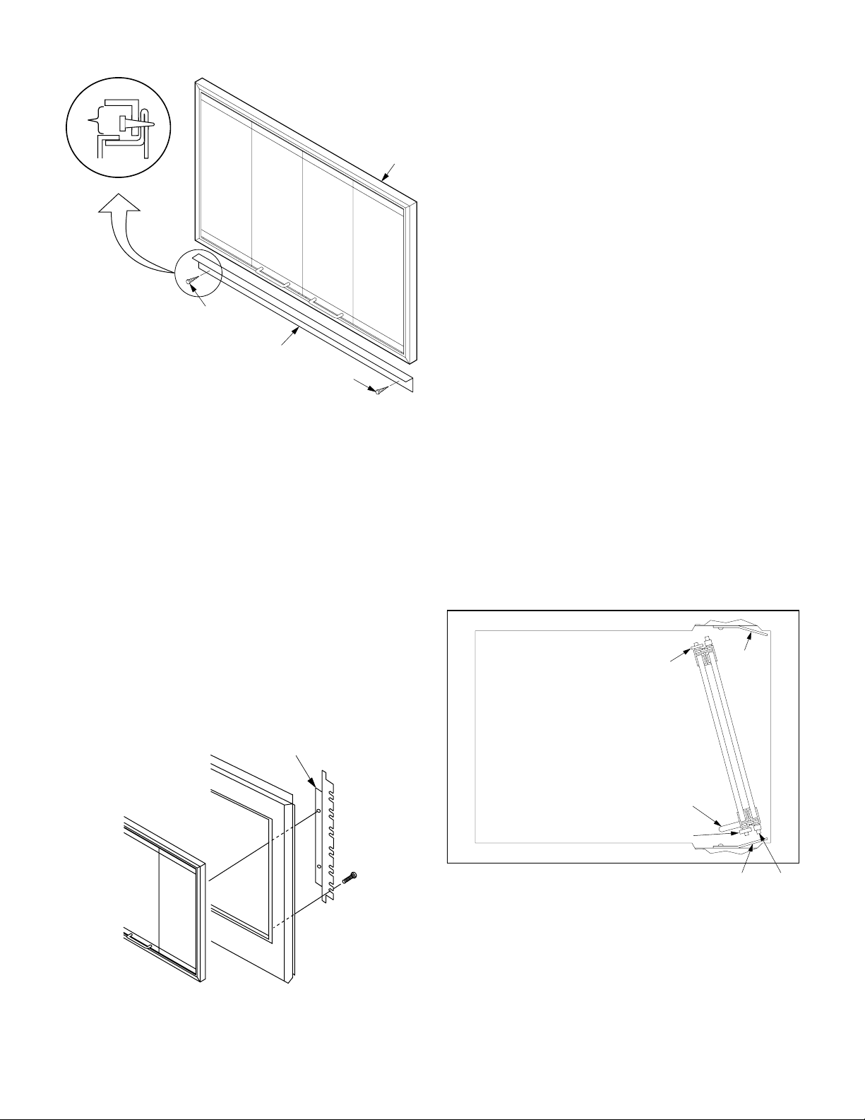
Step 1. Position the door support bracket along the lower front face of
theapplianceash lip, oriented as shown (
seeFigure 1
)(DO NOT affix the
door support bracket to the outer front face of the appliance). Using the
two (2) self tapping screws provided, secure the door support bracket
to the front of the ash lip.
Step 2. Position the frame in the fireplace opening on top of the door
support bracket, centering left and right. Mark the fireplace at each hole
in the side panels.
Note: Theframeisprovidedwith twosetsof holesallowingfor near"Flush
Face" installation and "Protruding" installations that may be particularly
useful in certain finish applications. In most cases the door frame will not
install completely flush with the appliance front face. The frame will
usually protrude from the opening approximately an 1/8 of an inch.
NOTE: DIAGRAMS & ILLUSTRATIONS NOT TO SCALE
2
Figure 1
Step 3. Remove the frame from the fireplace and drill a pilot hole 5/64"
diameter at each of the four marks. Re-position the frame into the
fireplace centering left and right. Insert the screws through the side
panel holes and screw them into the pilot holes just drilled.
Model Estate 48 Fireplaces
Note: The Center Wedge Clip located inside the track in the center of the
door frame indicates the bottom of the frame. It is important that the
frame be installed with the correct side up to insure smooth operation
of the doors.
Step 1. Lay the frame face down on a clean, soft surface to avoid
scratchingthebrass. NotethetwoPhillipsScrewsmountedtoTinnerman
nutsoneachofthesidepanels,loosenthesescrewstoallowadjustment
of the position of these Tinnerman nuts. Position the nuts to align with
the round holes on the Estate 48 attachment brackets (see
Figure 2
). Do
Not attach brackets to the door at this time.
Figure 2
Step 2. Locate the Phillips heads of the screws just around the back of
thefireboxopening atboththeright andleftsides. The slots oftheEstate
48 attachment brackets will engage these screws and be secured in
place by their heads. Back these screws out about an 1/8 of an inch.
Step 3. Position the Estate 48 attachment bracket within the fireplace
opening with their black faces forward and their slots engaged around
the screws backed out in the previous step. Snug up two (2) screws on
each side, DO NOT TIGHTEN. The attachment brackets must be allowed
to move in the following step.
Step 4. Remove the Phillips screw from the Tinnerman nuts in the door
frame assembly. Position the frame within the opening and align the
Tinnerman nuts with the four round holes of the attachment brackets,
two (2) on each side. Secure the frame to the brackets with the four (4)
screws, DO NOT TIGHTEN.
Step 5. Center the door frame within the opening, left to right and push
door frame up to the top of the opening as far as it will go. Carefully
tighten all screws, making sure they are not overtightened. Do Not
obstruct the gaps to the left and right of the frame. These spaces are
designed for inlet air to enter the fire box.
Installing the Doors
Install all doors as follows:
Fold panes of right door back to back with handle down as shown in
Figure 3
. Tilt door so that it fits inside frame as shown. Next, insert
Bottom Pin into Bottom Retainer Slot. Then tilt top of door toward
vertical position making sure that all Pins and Door Guides are inside
Track. Finally, slide Top Pin along Top Retainer Clip until Top Pin snaps
into Top Retainer Slot. Repeat procedure for left door.
Figure 3
Screw
Support
Bracket
Door
Screw
*
Note: This is an air inlet.
DO NOT cover this space
with any materials.
*
Detail
Top
(Narrow) Door Guide
(Wide) Door Guide
Retainer
Clip
Bottom Bottom
Pin
Retainer
Clip
Handle
Attachment
Bracket

NOTE: DIAGRAMS & ILLUSTRATIONS NOT TO SCALE 3
Fully Open or
Fully Closed
Front-Open Systems
CLEANING
NEVER CLEAN THE GLASS WHEN THE DOORS ARE HOT. DO NOT USE
AMMONIAORANYAMMONIABASEDGLASSORHOUSEHOLDCLEANER
TO CLEAN THE GLASS OR THE DOOR FRAME. AN AMMONIA BASED
CLEANER WILL DAMAGE THE FINISH.
Remove dirt and grime from the doors using a clean dampened towel
followed by wiping with a dry towel. To remove stubborn stains from the
doors, use a mild soap solution and towel to gently scrub away stain.
Take care not to scratch the glass surface. Do not use abrasive cleaners.
IMPORTANT
These glass doors utilize tempered glass which is designed for use
with high temperatures but can unexpectedly shatter. DO NOT SIT
CLOSE TO THE GLASS.
Tempered glass will break into small particles if it should shatter
unexpectedly. If the glass breaks, particles of extremely hot glass could
be discharged into the surrounding environment, thereby creating a risk
ofpersonal injuryor fire.Observationoftheaboveoperatingprecautions
and instructions will reduce the risk of personal injury or fire.
Extreme temperature changes can cause breakage — do not build a hot
fire and close the doors if the doors are cold.
If the tempered glass pane becomes scratched or chipped, it creates a
weakness in the glass which can cause the glass to break when heated.
Replace the pane of glass by contacting your nearest distributor. For the
name of your nearest distributor contact:
LENNOX HEARTH PRODUCTS
1110 West Taft Avenue
Orange, CA 92865
Figure 4
WARNING:DO NOT BURNTRASH, CONSTRUCTION SCRAPS,
RAILROAD TIES, OR OTHER HIGHLY-FLAMMABLE MATE-
RIAL IN THE FIREPLACE. INTENSE HEAT CAN CAUSE THE
GLASS TO LOSE STRENGTH AND RESILIENCE WHICH WILL
RESULT IN GLASS BREAKAGE.
ADJUSTMENT FOR DOOR ALIGNMENT
The doors are properly adjusted when the top door trim is in a straight,
level line and the gap between the doors and the frame is even at the top
and bottom. The doors can be adjusted by changing the location of the
door inside the frame. The door may need adjustment for several
reasons. One would be that the doors do not fully close because they hit
in the center of frame. Another would be that there is a noticeable gap
in the center between the closed doors.
If doors appear to close in correct position but do not latch (both doors
do not stay closed), then there is a misalignment between the doors and
the Center Wedge Clip. The Center Wedge Clip is located in the center
ofthebottomTrack. In order to stay closed,theleftandright doors must
meet in the Middle of the Center Wedge Clip.
To adjust doors, first loosen, but DO NOT remove the Phillips Screw that
holds the Retainer Clip to the frame. Move door to desired position then
tighten screw. Repeat procedure for other Retainer Clips as needed.
Operate doors to check alignment and repeat procedure if necessary.
GENERAL OPERATING PRECAUTIONS AND INSTRUCTIONS
CAUTION: THESE GLASS DOORS ARE LISTED ONLY FOR USE WITH
THE LENNOX FIREPLACE OR APPLIANCE MODELS SHOWN. USE ON
ANY OTHER FIREPLACE OR APPLIANCE MAY CONSTITUTE A POTEN-
TIAL FIRE HAZARD.
•Avoid building extremely large fires as the tempered glass could
become damaged.
•Use fireplace tools carefully to avoid striking the glass.
•Keep wire mesh screens closed during fireplace use.
•The fireplace flue damper must remain open until fire is completely
out.
•Assure wood and embers are well within the confines of the grate area
and well away from the glass doors.
•Keep wire mesh screens closed during fireplace use.
•Keep glass doors closed at night when retiring to minimize the loss of
heated room air up the vent.
CAUTION: THE FRONT-OPEN FIREPLACE OR APPLIANCE SHOULD
ONLYBE OPERATEDWITHTHE GLASSDOORSFULLY OPENORFULLY
CLOSED (
SEE FIGURE 4
).
CAUTION: GLASS AND METAL FRAMES GET HOT — ALWAYS USE
HANDLES TO OPEN AND CLOSE THE DOORS.
To remove the doors, open door all the way until glass panes are back
toback. Whilepushingdownondoor, push up on Top Retainer Clip with
finger to free Top Pin and rotate top of door toward center of frame.
Carefully remove door.

NOTE: DIAGRAMS & ILLUSTRATIONS NOT TO SCALE
Printed in U.S.A. © 2001 by LENNOX
P/N 750,108M REV. N/C 07/2001 1110 West Taft Avenue
Orange, CA 92865
LENNOX reserves the right to make changes at any time, without notice, in design,
materials, specifications, prices and also to discontinue colors, styles and products.
Consult your local distributor for fireplace code information.
This manual suits for next models
11
Other Lennox Door manuals

Popular Door manuals by other brands


Lennox Hearth Products
Lennox Hearth Products MPB-35 installation instructions

Ives
Ives Offset Top Pivot 7245F installation instructions

KitchenAid
KitchenAid KBAU181V Installation instructions and use and care guide

Ives
Ives 670 Installation and maintenance instructions

Ives
Ives Mortise Bolt S48 installation instructions

American Standard
American Standard Acrylux 6000Y1.BE5 Specifications