manuals.online logo
Brands
  1. Home
  2. •
  3. Brands
  4. •
  5. Lennox
  6. •
  7. Furnace
  8. •
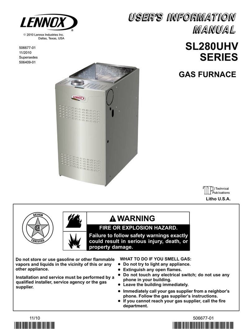
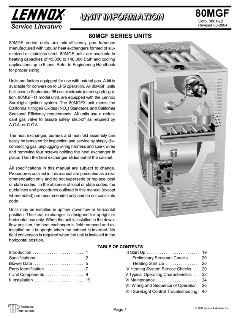
  9. Lennox iComfort SL280UH070V36A User manual

Lennox iComfort SL280UH070V36A User manual

Page 1 ©2016 Lennox Industries Inc.
Corp. 1116-L4
SL280UHV(X)
Service Literature Revised 04/2020
iComfort®ENABLED SL280UHV(X) SERIES UNITS
SL280UHV(X) series units are 80% efficiency gas furnaces
used for upflow or horizontal applications only, manufac
tured with Lennox Duralokheat exchangers formed of
aluminized steel. SL280UHV(X) units are available in heat
ing capacities of 66,000 to 132,000 Btuh and cooling ap
plications up to 5 tons. Refer to Engineering Handbook for
proper sizing.
Units are factory equipped for use with natural gas. Kits are
available for conversion to LPG operation. SL280UHV(X)
model units are equipped with the iComfort®enabled Sur
eLight®two-stage variable speed integrated control.
SL280UHV(X) unit meets the California Nitrogen Oxides
(NOx) Standards and California Seasonal Efficiency re
quirements. All units use a redundant gas valve to assure
safety shut-off as required by C.S.A.
All specifications in this manual are subject to change. Pro
cedures outlined in this manual are presented as a recom
mendation only and do not supersede or replace local or
state codes. In the absence of local or state codes, the
guidelines and procedures outlined in this manual (except
where noted) are recommendations only and do not consti
tute code.
TABLE OF CONTENTS
Specifications Page 2.............................
I Unit Components Page 5........................
II Installation Page 43.............................
III Start Up Page 43..............................
IV Heating System Service Checks Page 44.........
V Typical Operating Characteristics Page 47.........
VI Maintenance Page 48..........................
VII Wiring and Sequence of Operation Page 51......
VIII Field Wiring and Jumper Settings Page 55.......
IX Program Unit Capacity Size Mode Page 59.......
X Troubleshooting Page 60........................
WARNING
Improper installation, adjustment, alteration, service
or maintenance can cause property damage, person
al injury or loss of life. Installation and service must
be performed by a licensed professional HVAC in
staller (or equivalent), service agency or the gas sup
plier.
CAUTION
As with any mechanical equipment, contact with
sharp sheet metal edges can result in personal in
jury. Take care while handling this equipment and
wear gloves and protective clothing.
Page 2
SPECIFICATIONS
Gas
Heating
Performance
Model No. SL280UH070V36A SL280UH090V36B SL280UH090V48B
Model No. - Low Nox SL280UH070XV36A - - - SL280UH090XV48B
1AFUE 80% 80% 80%
High
Fire
Input - Btuh 66,000 88,000 88,000
Output - Btuh 52,000 70,000 70,000
Temperature rise range - °F 40 - 70 40 - 70 40 - 70
Gas Manifold Pressure (in. w.g.)
Nat. Gas / LPG/Propane
3.5 / 10 3.5 / 10 3.5 / 10
Low
Fire
Input - Btuh 43,000 57,000 57,000
Output - Btuh 35,000 47,000 47,000
Temperature rise range - °F 25 -55 25 -55 25 -55
Gas Manifold Pressure (in. w.g.)
Nat. Gas / LPG/Propane
1.7 / 4.9 1.7 / 4.9 1.7 / 4.9
High static - in. w.g. Heating 0.8 0.8 0.8
Cooling 1.0 1.0 1.0
Connections
in.
Flue connection − in. round 4 4 4
Gas pipe size IPS 1/2 1/2 1/2
Indoor
Blower
Wheel nominal diameter x width - in. 10 X 8 10 X 9 11-1/2 X 9
Motor output - hp 1/2 1/2 1.0
Tons of add-on cooling 2 - 3 2 - 3.5 2.5 - 4
Air Volume Range - cfm 606 - 1345 498 - 1393 679 - 2002
Electrical Data Voltage 120 volts - 60 hertz - 1 phase
Blower motor full load amps 7.7 7.7 12.8
Maximum overcurrent protection 15 15 20
Shipping Data lbs. - 1 package 128 143 154
NOTE - Filters and provisions for mounting are not furnished and must be eld provided.
1 Annual Fuel Utilization Efciency based on DOE test procedures and according to FTC labeling regulations. Isolated combustion system rating for non-weatherized
furnaces.
2 Flue connection on the unit is 4 in. diameter. Most applications will require 5 in. venting and eld supplied 4 x 5 in. adaptor. See Venting Tables in the Installation
Instructions for detailed information.
SPECIFICATIONS
Gas
Heating
Performance
Model No. SL280UH090V60C SL280UH110V60C SL280UH135V60D
Model No. - Low Nox - - - SL280UH110XV60C - - -
1AFUE 80% 80% 80%
High
Fire
Input - Btuh 88,000 110,000 132,000
Output - Btuh 70,000 87,000 105,000
Temperature rise range - °F 35 - 65 35 - 65 40 - 70
Gas Manifold Pressure (in. w.g.)
Nat. Gas / LPG/Propane
3.5 / 10.0 3.5 / 10.0 3.5 / 10.0
Low
Fire
Input - Btuh 57,000 71,500 85,800
Output - Btuh 47,000 58,000 69,000
Temperature rise range - °F 25 -55 25 -55 25 -55
Gas Manifold Pressure (in. w.g.)
Nat. Gas / LPG/Propane
1.7 / 4.9 1.7 / 4.9 1.7 / 4.9
High static - in. w.g. Heating 0.8 0.8 0.8
Cooling 1.0 1.0 1.0
Connections
in.
Flue connection − in. round 4 4 24
Gas pipe size IPS 1/2 1/2 1/2
Indoor
Blower
Wheel nominal diameter x width - in. 11-1/2 X 10 11-1/2 X 10 11-1/2 X 11
Motor output - hp 1.0 1.0 1.0
Tons of add-on cooling 3 - 5 3 - 5 3.5 - 5
Air Volume Range - cfm 826 - 2305 812 - 2125 828 - 2257
Electrical Data Voltage 120 volts - 60 hertz - 1 phase
Blower motor full load amps 12.8 12.8 12.8
Maximum overcurrent protection 20 20 20
Shipping Data lbs. - 1 package 173 181 199
NOTE - Filters and provisions for mounting are not furnished and must be eld provided.
1 Annual Fuel Utilization Efciency based on DOE test procedures and according to FTC labeling regulations. Isolated combustion system rating for non-weatherized
furnaces.
2 Flue connection on the unit is 4 in. diameter. Most applications will require 5 in. venting and eld supplied 4 x 5 in. adaptor. See Venting Tables in the Installation
Instructions for detailed information.
Page 3
OPTIONAL ACCESSORIES - MUST BE ORDERED EXTRA
“A” Width
Models
“B” Width
Models
“C” Width
Models
“D” Width
Models
CABINET ACCESSORIES
Horizontal Suspension Kit - Horizontal only 51W10 51W10 51W10 51W10
Return Air Base - Upow only 65W75 50W98 50W99 51W00
CONTROLS
ComfortSense® 7000 Thermostat Y0349 Y0349 Y0349 Y0349
Remote Outdoor Sensor (for dual fuel and Humiidtrol®) X2658 X2658 X2658 X2658
FILTERS
1 Air Filter and Rack Kit Horizontal (end) 87L95 87L96 87L97 87L98
Size of lter - in. 14 x 25 x 1 18 x 25 x 1 20 x 25 x 1 25 x 25 x 1
Side Return Single 44J22 44J22 44J22 44J22
Ten Pack 66K63 66K63 66K63 66K63
Size of lter - in. 16 x 25 x 1 16 x 25 x 1 16 x 25 x 1 16 x 25 x 1
NIGHT SERVICE KITS
Night Service Kit 14C98 14C98 14C98 14C98
Safety Service Kit 89W19 89W19 89W19 89W19
1 Cleanable polyurethane, frame-type lter.
GAS HEAT ACCESSORIES
Input Natural Gas to
LPG/Propane Kit
LPG/Propane
to Natural Gas Kit
All models 11K51 11K46
Page 4
FIGURE 1
HEAT EXCHANGER
CABINET
COMBUSTION AIR INDUCER
BLOWER
ASSEMBLY
BURNER BOX
INNER BLOWER
ACCESS PANEL
ACCESS PAN
EL
SIGHT GLASS
COMBUSTION AIR INDUCER
PRESSURE SWITCH
GAS VALVE
CONTROL BOX
(Includes two-stage integrated control,
transformer and circuit breaker)
SECONDARY LIMITS
(2 switches)
PRIMARY LIMIT
SL280UHV Parts Arrangement
Page 5
I-UNIT COMPONENTS
SL280UHV(X) unit components are shown in figure 1. The
gas valve, combustion air inducer and burners can be ac
cessed by removing the access panel. Electrical compo
nents are in the control box (figure 2) found in the blower
section.
SL280UHV(X) units are factory equipped with a bottom return
air panel in place. The panel is designed to be field removed
as required for bottom air return. Markings are provided for
side return air and may be cut out in the field.
CAUTION
Electrostatic discharge can affect elec
tronic components. Take precautions
to neutralize electrostatic charge by
touching your hand and tools to metal
prior to handling the control.
A- Control Box
1. Control Transformer (T1)
A transformer located in the control box provides power to
the low voltage section of the unit. Transformers on all
models are rated 40VA with a 120V primary and a 24V sec
ondary.
2. Door Interlock Switch (S51)
A door interlock switch rated 14A at 125VAC is wired in se
ries with line voltage. When the inner blower access panel
is removed the unit will shut down.
FIGURE 2
CONTROL BOX SL280UHV
Transformer
SureLight®Integrated Control
Interlock Switch
Circuit Breaker
3. Circuit Breaker (CB8)
A 24V circuit breaker is also located in the control box.
The switch provides overcurrent protection to the trans
former (T1). The breaker is rated 3A at 32V. If the current
exceeds this limit the breaker will trip and all unit opera
tion will shutdown. The breaker can be manually reset
by pressing the button on the face. See figure 3.
FIGURE 3
CIRCUIT BREAKER CB8
PRESS TO RESET
WARNING
Shock hazard.
Disconnect power before servicing. Integrated
control is not field repairable. If control is inoper
able, simply replace entire control.
Can cause injury or death. Unsafe operation will re
sult if repair is attempted.
4. Integrated Control (A92)
Units are equipped with the icomfortenabled Sur
eLight®two-stage, variable speed integrated control. This
control is used with the icomfort Wi-Fi®thermostat as part
of a communicating comfort system. The control can also
operate with a non-communicating conventional single or
two-stage thermostat. The system consists of a ignition /
blower control (figures 4 and 5) with control pin designa
tions in tables 1, 2 and 3 and ignitor (figure 13). The control
and ignitor work in combination to ensure furnace ignition
and ignitor durability. The control provides gas ignition,
safety checks and indoor blower control with two-stage gas
heating. The furnace combustion air inducer, gas valve and
indoor blower are controlled in response to various system
inputs such as thermostat signal, pressure and limit switch
signal and flame signal. The control features a seven-seg
ment LED display, indicating furnace status (including in
door blower) and error codes. The LED flashes in single
digits. For example using table 5 under LIMIT CODE, an
“E” followed by “2” followed by “5” followed by “0”, the limit
switch circuit is open. The control also has two unpowered
(dry) 1/4” contacts for a humidifier and a 120 volt accessory
terminal. Both rated at (1) one amp each.
Electronic Ignition
At the beginning of the heat cycle the integrated control
monitors the first stage and second stage combustion air
inducer prove switch. The control will not begin the heating
cycle if the first stage prove switch is closed (by-passed).
Likewise the integrated control will not begin the second
stage heating cycle if the second stage prove switch is
closed, and will remain in first stage heat. However, if the
second stage prove switch closes during the first stage
heat pre-purge, the control will allow second stage heat.
Once the first stage prove switch is determined to be open,
Page 6
the combustion air inducer is energized on low (first stage)
heat speed. When the differential in the prove switch is
great enough, the prove switch closes and a 15-second
pre-purge begins.
NOTE - During abnormal conditions such as low supply
voltage or low outdoor temperatures and the low fire pres
sure switch does not close, the combustion air inducer will
switch to high fire. After a 15 second pre-purge the high fire
pressure switch will close and the unit will begin operation
on high fire. After 10 to 20 seconds of high fire operation the
unit will switch to low fire.
After the 15-second pre-purge period, the SureLight ignitor
warms up for 20 seconds after which the gas valve opens
for a 4-second trial for ignition. The ignitor energizes during
the trial until flame is sensed. If ignition is not proved during
the 4-second period, the control will try four more times with
an inter purge and warm-up time between trials of 35 sec
onds. After a total of five trials for ignition (including the ini
tial trial), the control goes into Watchguard-Flame Failure
mode. After a 60-minute reset period, the control will begin
the ignition sequence again.
Two Stage Operation / Thermostat Selection DIP
Switch
The control can be utilized in two modes: SINGLE-STAGE
thermostat or TWO-STAGE thermostat. The thermostat
selection is made using a DIP switch and must be posi
tioned for the particular application. DIP switch 1, labeled
T”STAT HEAT STAGE is factory-set in the OFF position for
use with a two-stage thermostat. Move the DIP switch to
ON for use with a single stage thermostat.
While in the single-stage thermostat mode, the burners will
always fire on first-stage heat. The combustion air inducer
will operate on low speed and indoor blower will operate on
low heat speed. The unit will switch to second stage heat
after a "recognition period". DIP switch 2, labeled SECOND
STAGE DELAY, is factory set in the OFF position for a 7
minute recognition period. The switch can be moved to the
ON position for a 12 minute recognition period, after which
time the unit will switch to secondstage heat.
While in the two-stage thermostat mode (two DIP switch
setting) the burners will fire on first-stage heat. The com
bustion air inducer will operate on low speed and indoor
blower will operate on low heat speed. The unit will switch
to second-stage heat on call from the indoor thermostat. If
there is a simultaneous call for first and second stage heat,
the unit will fire an first stage heat and switch to second
stage heat after 30 seconds of operation. See Sequence of
Operation flow charts in the back of this manual for more
detail.
TABLE 1
SureLight®Control 5 Pin Terminal Designation
PIN # Function
1 Ignitor
2Combustion Air Inducer High Speed
3Combustion Air Inducer Low Speed
4Combustion Air Inducer Neutral
5Ignitor Neutral
TABLE 2
SureLight®Control 12 Pin Terminal Designation
PIN # Function
1Gas Valve High Fire
2Second Stage Prove Switch
3Rollout In
4 Ground
524V Hot
6Primary Limit In
7Gas Valve Low Stage
8Gas Valve Common
924V Neutral
10 Ground
11 Rollout Switch Out
12 1st Stage Prove Switch
TABLE 3
SureLight®Control 6 Pin Terminal Designation
PIN # Function
1Data Input From Motor
2 Common
3Not Used
4Data Output To Motor
55 Volt Bias Supply
6Not Used
Page 7
FIGURE 4
THERMOSTAT CONNECTIONS (TB1)
1/4” QUICK CONNECT TERMINALS
RS-BUS LINK (TB82, future use)
I+ = DATA HIGH CONNECTION
I - = DATA LOW CONNECTION
RS-BUS OUTDOOR (TB83)
R = 24VAC
I + = DATA HIGH CONNECTION
I - = DATA LOW CONNECTION
C = 24VAC COMMON
RS-BUS INDOOR (TB84)
R = 24VAC
I + = DATA HIGH CONNECTION
I - = DATA LOW CONNECTION
C = 24VAC COMMON
FLAME SENSE
DIP SWITCHES
OUTDOOR AIR
SENSOR
TERMINALS
DISCHARGE AIR
SENSOR
TERMINALS
INDOOR
BLOWER
CONNECTOR
NEUTRAL
DIAGNOSTIC
PUSH BUTTON
TB83
COMMUNICATING
OUTDOOR
EQUIPMENT
TB84
COMMUNICATING
INDOOR
THERMOSTAT
DS = DEHUMIDIFICATION SIGNAL
W2 = HEAT DEMAND FROM 2ND STAGE T/STAT
W1 = HEAT DEMAND FROM 1ST STAGE T/STAT
R = CLASS 2 VOLTAGE TO THERMOSTAT
G = MANUAL FAN FROM T'STAT
C = THERMOSTAT SIGNAL GROUND CONNECTED TO
TRANSFORMER GRD (TR) & CHASIS GROUND (GRD)
Y1 = THERMOSTAT 1ST STAGE COOL SIGNAL
Y2 = THERMOSTAT 2ND STAGE COOL SIGNAL
O = THERMOSTAT SIGNAL TO HEAT PUMP
REVERSING VALVE
L = USE ONLY WITH A COMMUNICATING THERMOSTAT
AND A NON-COMMUNICATING OUTDOOR UNIT
DH = DEHUMIDIFICATION OUTPUT COMMUNICATING
THERMOSTAT ONLY
HUM = UNPOWERED NORMALLY OPEN (DRY) CONTACTS
XMFR = 120 VAC OUTPUT TO TRANSFORMER
LI = 120 VAC INPUT TO CONTROL
ACC = 120 VAC OUTPUT TO OPTIONAL ACCESSORY
NEUTRALS = 120 VAC NEUTRAL
W915 Y1 TO Y2
2 STAGE COMPR
W951 R TO O
HEAT PUMP
W914 R TO DS
DEHUM OR
HARMONY
W1 W2 G Y2 Y1 CCRDHLODS
RI + I - CRI + I - C
7 SEGMENT LED
ACC
LINE 1
HUM
12 PIN LOW
VOLTAGE
CONNECTOR
NON-COMMUNICATINGNG
24V TERMINALS
HS/ CAI
INTEGRATED CONTROL
Page 8
FIGURE 5
HEATING BLOWER−OFF DELAY
60 SECOND
HTG BLOWER
OFF DELAY
120 SECOND
HTG BLOWER
OFF DELAY
180 SECOND
HTG BLOWER
OFF DELAY
FLAME
15
HSI/CAI
2ND STAGE HEAT ON DELAY
7 MIN
UPSTAGE
DELAY
12 MIN
UPSTAGE
DELAY
*CONTINUOUS FAN MODE BLOWER SPEED
COOLING MODE BLOWER RAMPING
CLG BLOWER SPEED ADJUSTMENT
COOLING MODE BLOWER SPEED
W915
2 STAGE
COMPR
1−STG COMPRESSOR
2−STAGE
COMPRESSOR LINK
(JUMPERS Y1 to Y2)
W915
DO NOT CUT
2−STG COMPRESSOR
HEAT PUMP LINK
(JUMPERS R to O)
W951
DEHUMIDIFICATION−
HARMONY LINK
(JUMPERS R to DS)
W914
W915
2 STAGE
COMPR
CUT LINK
A/C UNIT
DO NOT CUT
HEAT PUMP UNIT
CUT LINK
W951
HEAT
PUMP
W951
HEAT
PUMP
W914
DEHUM
or
NO HARMONY ZONING
OR
NO SIGNATURESTAT
W/ DS CONNECTION
DO NOT CUT
HARMONY ZONING
OR
SIGNATURESTAT W/
DS CONNECTION
CUT LINK
HARMONY
W914
DEHUM
or
HARMONY
1
1
1
ON−BOARD LINK
OPTION SELECTION
1234567
1234567
123567
4
123567
4
NEUTRALS
L1
ACC
HUM
14
36
P79
110
312
J2
4 7
W915
2 STAGE
COMPR
W951
HEAT
PUMP
W914
DEHUM
HARMONY
CUT FOR
OPTION
SELECTION
OUTDOOR
SENSOR
DISCHARGE
AIR SENSOR
123456
10 12
911
13
ON
ON
SureLight®
W1W2 GY2 Y1 C C DHL O DSR
W1
W2
G
Y2
Y1
C
C
R
L
DH
HIGH
SPEED
(100%)
MEDIUM−HIGH
SPEED
(70%)
MEDIUM−LOW
SPEED
(38%)
LOW
SPEED
(28%)
*
OPTION A
OFF−50%−82%−
100%−50%−OFF
OPTION B
OFF−82%−100%−OFF
OPTION C
OFF−100%−100%−OFF
OPTION D
OFF−100%−OFF
*
DEFAULT
+ 10%
− 10%
*
HIGH
SPEED
MEDIUM−HIGH
SPEED
MEDIUM−LOW
SPEED
LOW
SPEED
*
7
−PROTECTIVE PLASTIC FILM ON DIP SWITCHES MAY BE
REMOVED FOR EASE IN SETTING OF DIP SW.
−CUT ON−BOARD LINK (SOLDER TRACE) COMPLETELY THROUGH
BOTH LAYERS ON THE CONTROL BOARD
−LINKS CUT IN ERROR −INSTALL A JUMPER ON THE APPROPRIATE
TERMINALS ON THE TERMINAL STRIP
1
910 11 12 13 14
ON
ON
ON
ON
ON
ON
ON
ON
90 SECOND
HTG BLOWER
OFF DELAY
*1234567
ON
1234567
ON
THERMOSTAT SELECTION
1−STAGE
THERMOSTAT
(TIMED STAGING)
−SEE SW #2
TWO STAGE
THERMOSTAT
*1234567
1234567
ON
ON
−BLOWER ON DELAY − 30 SEC. FIXED
15
910 11 12 14 15
910 11 12 14 15
910 11 12 14 15
8
8
8
8
8
8
8
81234567
1234567
ON
ON
1234567
ON
1234567
ON
8
8
8
8
910 11 12 13 14
ON
ON
ON
ON
15
910 11 12 14 15
910 11 12 14 15
910 11 12 14 15
910 11 12 13 14
ON
ON
ON
ON
15
910 11 12 14 15
910 11 12 14 15
910 11 12 14 15
HEATING MODE BLOWER SPEED
1234567
ON
1234567
ON
1234567
ON
8
8
8
910 11 12 13 14
ON
ON
ON
ON
15
910 11 12 14 15
910 11 12 14 15
910 11 12 14 15
FACTORY
DEFAULT
+ 24%
+ 18%
+ 12%
+ 6%
− 6%
− 12%
− 18%
8
14 15
INCREASE AIR HTG CFM
DECREASE AIR HTG CFM
SENSE
RI+ I− CRI+ I− C
OUTDOOR EQUIPMENT
I+ I−
INDOOR EQUIPMENT
IGN
CAI2
CAI1
N
N
J3
S1
S4S3
13
13
13
13
13
13
13
* FACTORY DEFAULT
13
13
*
DIAGNOSTIC
LED
DIAGNOSTIC
PUSH BUTTON
INTEGRATED CONTROL CONFIGURATION GUIDE
Page 9
TABLE 4
Integrated Control Diagnostic Modes
Display Action (when button released)
No change (idle)* Remain in idle mode
Solid “E” Enter diagnostic recall mode
Solid “D” Discharge Air Installed
Solid “F” Enter flame signal mode
Solid “P” (variable speed only) Program unit capacity/size (Unit Code)
* No change implies the display will continue to show whatever is currently being displayed for normal operation (blinking
decimal, active error code, heat state, etc..)
Diagnostic LED (Figure 4)
The seven-segment diagnostic LED displays operating
status, target airflow, error codes and other information.
The table beginning on Page 10 lists diagnostic LED
codes.
Diagnostic Push Button (Figure 4)
The diagnostic push button is located adjacent to the
seven-segment diagnostic LED. This button is used to en
able the Error Code Recall “E” mode and the Flame Signal
“F” mode. Press the button and hold it to cycle through a
menu of options. Every five seconds a new menu item will
be displayed. When the button is released, the displayed
item will be selected. Once all items in the menu have been
displayed, the menu resumes from the beginning until the
button is released.
Error Code Recall Mode
Select ”E” from the menu to access the most recent 10 error
codes. Select “c” from the Error Code Recall menu to clear
all error codes. Button must be pressed a second time
while “c” is flashing to confirm command to delete codes.
Press the button until a solid “≡” is displayed to exit the Error
Code Recall mode.
Flame Signal Mode
Select ”F” from the menu to access the flame signal mode.
The integrated control will display the flame current on 7
segment LED in in micro amps (uA).
Flame signal mode is exited after any of the following:
Power is reset
Pressing and holding push button until 3 horizontal
lines “≡” are displayed
10 minutes after entering the flame sense mode.
Program Unit Capacity/Size Mode
After the “P” is selected (by releasing the push button) the
integrated control will start flashing the “P” on display for 90
seconds. If push button is pressed again and held during
that time, the control will start to display characters corre
sponding to different variable speed furnace models for 3
seconds each. While the wanted character-model is dis
played push button has to be released. Selected option will
flash display for 10 seconds and during that time push but
ton has to be pressed and held for 5 seconds. Once control
accepts new setting it will store data in non-volatile memory
and reset itself. If 10 seconds expires or push button is held
less than 5 seconds, control will exit field test mode and go
into idle without changing programming the unit size.
Page 10
TABLE 5
Integrated Diagnostic Codes/Status of Equipment I.
Code Diagnostic Codes/Status of Equipment Action Required to Clear and Recover
.Idle mode (Decimal blinks at 1 Hertz -- 0.5 second ON, 0.5 second OFF).
ACubic feet per minute (cfm) setting for indoor blower (1 second ON, 0.5
second OFF) / cfm setting for current mode displayed.
CCooling stage (1 second ON, 0.5 second OFF) / 1 or 2 displayed / Pause
/ cfm setting displayed / Pause / Repeat codes).
dDehumidification mode (1 second ON) / 1 second OFF) / cfm setting dis
played / Pause / Repeat Codes).
hHeat pump stage (1 second ON, 0.5 second OFF) / % of input rate dis
played / Pause / cfm setting / Pause / Repeat codes.
HGas Heat Stage (1 second ON, 0.5 second OFF) / 1 or 2 displayed /
Pause / cfm
setting displayed / Pause / Repeat codes. Blinking during ignition.
dF Defrost mode.
UDischarge Air Temperature
E 105 Device communication problem - No other devices on RS BUS (Commu
nication
system).
Equipment is unable to communicate. Indicates
numerous message errors. In most cases errors are
related to electrical noise. Make sure high voltage
power is separated from RSBus. Check for mis-
wired and/or loose connections between the stat,
indoor unit and outdoor unit. Check for a high volt
age source of noise close to the system. Fault
clears after communication is restored.
E 110 Low line voltage. Line Voltage Low (Voltage lower than nameplate
rating). Check power line voltage and correct. Alarm
clears 5 seconds after fault recovered.
E 111 Line voltage polarity reversed. Reverse line power voltage wiring. System resumes
normal operation 5 seconds after fault recovered.
E 112 Ground not detected System shuts down. Provide proper earth ground.
System resumes normal operation 5 seconds after
fault recovered.
E 113 High line voltage. Line Voltage High (Voltage higher than nameplate
rating). Provide power voltage within proper range.
System resumes normal operation 5 seconds after
fault recovered.
E 114 Line voltage frequency out-of-range. No 60 Hertz Power. Check voltage and line power
frequency. Correct voltage and frequency problems.
System resumes normal operation 5 seconds after
fault recovered.
E 115 Low 24V - Control will restart if the error recovers. 24-Volt Power Low (Range is 18 to 30 volts). Check
and correct voltage. Check for additional power-rob
bing equipment connected to system. May require
installation of larger VA transformer to be installed
in furnace / air handler. Clears after fault recovered.
E 116 High 24V. 24 Volt Power High (Range is 18 to 30 volts). Check
and correct voltage. Check for proper line voltage
(120V, 240V, etc.) to equipment. Clears when con
trol senses proper voltage.
E 117 Poor ground detected (Warning only) Provide proper grounding for unit. Check for proper
earth ground to the system. Warning only will clear
30 seconds after fault recovered.
E 120 Unresponsive device. Communication only. Usually caused by delay in outdoor unit responding
to indoor unit poling. Recycle power. Check all wir
ing connections. Cleared after unresponsive device
responds to any inquiry.
Page 11
TABLE 5 Continued
Code Diagnostic Codes/Status of Equipment Action Required to Clear and Recover
E 124 Active communicating thermostat signal missing for more than 3 min
utes.
Equipment lost communication with the thermostat.
Check four wiring connections, ohm wires and cycle
power at the thermostat. Alert stops all services and
waits for heartbeat message from thermostat (sub
net controller). Cleared after valid thermostat (sub
net controller) message is received.
E 125 Control failed self-check, internal error, failed hardware. Will restart if
error
recovers. Integrated control not communicating. Covers hardware errors
(flame sense circuit faults, pin shorts, etc.).
Hardware problem on the control. Cycle power on
control. Replace if problem prevents service and is
persistent. Critical alert. Cleared 300 seconds after
fault recovered.
E 126 Control internal communication problem. Hardware problem on the control. Cycle power on
control. Replace if problem prevents service and is
persistent. Cleared 300 seconds after fault recov
ered.
E 131 Corrupted control parameters (Verify configuration of system). Communi
cating only.
Reconfigure the system. Replace control if heating
or cooling is not available. Only applicable in the
communicating mode, not in startup. Exit from Com
missioning and Execute 'Set Factory Default mode'.
Control will still operate on default parameter set
tings.
E 180 Outdoor air temperature sensor failure. Only shown if shorted or out-of-
range.
Compare outdoor sensor resistance to temperature/
resistance charts in unit installation instructions.
Replace sensor pack if necessary. At beginning of
(any) configuration, furnace or air handler control
will sense outdoor air and discharge air temperature
sensor(s). If detected (reading in range), appropri
ate feature will be set as 'installed' and that could be
seen in 'About' screen. In normal operation after
control recognizes sensors, alarm will be sent if
valid temperature reading is lost. To get rid of set
ting and alarm, redo configuration and make sure
that temperature sensor is marked as 'not installed'
in Indoor Unit 'About' screen. When Indoor unit con
trol is replaced, thermostat will 'tell' new control if
temperature sensor is in system or not. Clears 30
seconds after fault recovered.
E 200 Hard lockout - Rollout circuit open or previously open. Correct cause of rollout trip, or replace flame rollout
switch. Test furnace operation. Cleared after fault
recovered.
E 201 Indoor blower communication failure - Unable to communicate with blow
er motor.
Indoor blower communication failure (including pow
er outage). Lost communication with indoor blower
motor. Possible causes: motor not powered, loose
wiring. Problem may be on control or motor side.
Cleared after fault recovered.
E 202 Indoor blower motor mis-match - Indoor motor horsepower does not
match unit capacity. See Page 59.
Incorrect appliance capacity code selected. Check
for proper configuring under: Unit Size Codes for
Furnace/Air Handler on configuration guide or in
installation instructions. Cleared after the correct
match is detected following a reset. (Remove ther
mostat from system while applying power and re
programming.)
E 203 Appliance capacity / size is NOT programmed. Invalid unit codes refer to
configuration flow chart. See Page 59.
No appliance capacity code selected. Check for
proper configuring under: Unit Size Codes for Fur
nace on configuration guide or in installation instruc
tions. Critical Alert. Cleared after valid unit code is
read following a reset. (Remove thermostat from
system while applying power and reprogramming.)
E 204 Gas valve mis-wired. Check gas valve operation and wiring. Clears when
repaired.
E 205 Gas valve control relay contact shorted. Check wiring on control and gas valve. If wiring is
correct, replace control.
Page 12
TABLE 5 Continued
Code Diagnostic Codes/Status of Equipment Action Required to Clear and Recover
E 206 Gas valve second-stage relay failure Furnace will operate on 1st stage for remainder of
the heating demand. Will clear after fault recovered.
If unable to operate 2nd stage, replace control.
E 207 Hot surface ignitor sensed open - Refer to troubleshooting. See Page 60. Measure resistance of hot surface ignitor. Replace if
open or not within specified range found in IOM.
Resumes normal operation after fault is cleared.
E 223 Low pressure switch failed open. Check pressure (inches w.c.) of low pressure switch
closing on heat call. Measure operating pressure
(inches w.c.). Inspect vent and combustion air in
ducer for correct operation and restriction. Re
sumes normal operation after fault is cleared
E 224 Low pressure switch failed closed - Refer to troubleshooting. See
Page 60.
Check operation of low pressure switch to see if it is
stuck closed on heat call longer than 150 seconds.
Measure operating pressure (inches w.c.). Inspect
vent and combustion air inducer for correct opera
tion and restriction. Resumes normal operation after
fault is cleared.
E 225 High pressure switch failed open - Refer to troubleshooting. See
Page 60.
Check pressure (inches w.c.) of high pressure
switch closing on heat call. Measure operating pres
sure (inches w.c.). Inspect vent and combustion air
inducer for correct operation and restriction. Re
sumes normal operation after fault is cleared.
E 226 High pressure switch failed closed - Refer to troubleshooting. See
Page 60.
Check operation of high pressure switch closing on
heat call. Measure operating pressure (inches w.c.).
Inspect vent and combustion air inducer for correct
operation and restriction. Resumes normal opera
tion after fault is cleared.
E 227 Low pressure switch open during trial for ignition or run mode. Refer to
troubleshooting. See Page 60.
Check pressure (inches w.c.) of low pressure switch
closing on heat call. Measure operating pressure
(inches w.c.). Inspect vent and combustion air in
ducer for correct operation and restriction. Re
sumes normal operation after fault is cleared.
E 228 Combustion air inducer calibration failure Unable to perform pressure switch calibration.
Check vent system and pressure switch wiring con
nections. Resumes normal operation after fault is
cleared.
E 229 Ignition on High Fire - Information Only Code is displayed if 1) low pressure switch fails to
close, then furnace will switch to high speed inducer
to close both low and high pressure switches, then
furnace lights on high fire, or 2) if continuous fan is
active, furnace lights on high fire for 60 seconds to
improve heat exchanger warm up time.
E 240 Low flame current - Run mode - Refer to troubleshooting. See Page 60. Check micro-amperes of flame sensor using control
diagnostics or field-installed mode. Clean or replace
sensor. Measure voltage of neutral to ground to
ensure good unit ground. Alert clears after current
heat call has been completed.
E 241 Flame sensed out of sequence - Flame still present. Shut off gas. Check for gas valve leak. Replace, if
necessary. Alert clears when fault is recovered.
E 250 Limit switch circuit open - Refer to troubleshooting. See Page 60 Check for proper firing rate on furnace. Ensure
there is no blockage in heater. Check for proper air
flow. If limit not closed within 3 minutes, unit will go
into 1-hour soft lockout. Resumes normal operation
after fault is cleared.
E 252 Discharge air temperature too high (gas heat only). Check temperature rise, air flow and input rate.
Cleared when heat call is finished.
E 270 Soft lockout - Exceeded maximum number of retries. No flame current
sensed.
Check for proper gas flow. Ensure that ignitor is
lighting burner. Check flame sensor current. Clears
when heat call finishes successfully.
Page 13
TABLE 5 Continued
Code Diagnostic Codes/Status of Equipment Action Required to Clear and Recover
E 271 Soft lockout - Exceeded maximum number of retries. Last retry failed due
to the pressure switch opening.
Check pressure (inches w.c.) of low pressure switch
closing on heat call. Measure operating pressure
(inches w.c.). Inspect vent and combustion air in
ducer for correct operation and restriction. Clears
when heat call finishes successfully.
E 272 Soft lockout - Exceeded maximum number of recycles. Last recycle due
to the pressure switch opening.
Check operation of low pressure switch to see if it is
stuck closed on heat call. Check pressure (inches
w.c.) of high pressure switch closing on heat call.
Measure operating pressure (inches w.c.). Inspect
vent and combustion air inducer for correct opera
tion and restriction. Clears when heat call finishes
successfully.
E 273 Soft lockout - Exceeded maximum number of recycles. Last recycle due
to flame failure.
Check micro-amperes of flame sensor using control
diagnostics or field-installed mode. Clean or replace
sensor. Measure voltage of neutral to ground to
ensure good unit ground. Clears when heat call
finishes successfully.
E 274 Soft lockout - Exceeded maximum number of recycles. Last recycle
failed due to the limit circuit opening or limit remained open longer than
3 minutes.
Shut down system. 1-hour soft lockout. Check firing
rate and air flow. Check for blockage. Clears when
heat call finishes successfully.
E 275 Soft lockout - Flame sensed out of sequence. Flame signal is gone. Shut off gas. Check for gas valve leak. 1-hour soft
lockout. Clears when flame has been proven stable.
E 276 Watchguard calibration failure. Unable to perform pressure switch calibration.
Check vent system and pressure switch wiring con
nections. 1-hour soft lockout. Clears when calibra
tion has finished successfully.
E 290 Ignitor circuit fault - Failed ignitor or triggering circuitry. Measure resistance of hot surface ignitor. Replace if
open or not within specifications. 1-hour soft lock
out. Clears when flame has been proven stable.
E 291 Heat air flow restricted below the minimum. Check for dirty filter and air flow restriction. Check
blower performance. 1-hour soft lockout. Cleared
when heat call finishes successfully.
E 292 Indoor blower motor unable to start due to obstructed wheel, seized
bearings.
Indoor blower motor unable to start (seized bear
ing, stuck wheel, etc.). Replace motor or wheel if
assembly does not operate or meet performance
standards. 1-hour soft lockout. Clears after circula
tor successfully starts.
E 294 Combustion air inducer over current. Check combustion blower bearings, wiring and
amps. Replace if does not operate or does not meet
performance standards. Clears after inducer current
is sensed to be in-range after the ignition following
the soft lockout or reset.
E 295 Indoor blower motor temperature is too high. Indoor blower motor over temperature (motor
tripped on internal protector). Check motor bearings
and amps. Replace if necessary. Cleared after
blower demand is satisfied.
E 310 Discharge error temperature sensor failure. Only shown if shorted or
out of range.
Compare outdoor sensor resistance to temperature/
resistance charts in installation instructions. Re
place sensor if necessary. Cleared in Communicat
ing mode: 30 seconds after fault recovered. In Non-
Communicating mode: Cleared after the current
heat call is completed.
E 311 Heat rate reduced to match indoor blower air flow. Warning Only. Furnace blower in cutback mode due
to restricted airflow. Reduce firing rate every 60
seconds to match available CFM. Check filter and
duct system. To clear, replace filter if needed or re
pair/add duct. 2-stage controls will reduce firing rate
to 1st stage. Clears when heat call finishes success
fully.
Page 14
TABLE 5 Continued
Code Diagnostic Codes/Status of Equipment Action Required to Clear and Recover
E 312 Restricted air flow in cooling or continuous fan mode is lower than cfm
setting.
Warning Only. Restricted airflow - Indoor blower is
running at a reduced CFM (Cutback Mode - The
variable speed motor has pre-set speed and torque
limiters to protect the motor from damage caused
by operating outside of design parameters (0 to 0.8”
W.C.. total external static pressure). Check filter
and duct system. To clear, replace filter if needed or
repair/add duct. Cleared after the current service
demand is satisfied.
E 313 Indoor or outdoor unit capacity mismatch. Communication only. Incorrect indoor/outdoor capacity code selected.
Check for proper configuring in installation instruc
tions. Alarm is just a warning. The system will oper
ate, but might not meet efficiency and capacity pa
rameters. Alarm will clear when commissioning is
exited. Cleared after commissioning is complete.
E 331 Global network connection - Communication link problem. For Future Use.
E 334 Relay “Y1” stuck on interated control. Replace integrated control.
E 347 No 24 Volt output on Y1 of ”integrated control” with non communicating
outdoor unit.
Operation stopped. Y1 relay / Stage 1 failed. (Pilot
relay contacts did not close or the relay coil did not
energize; no input back to IFC chip). Critical Alert.
Cleared after reset and Y1 input sensed.
E 348 No 24 Volt output on Y2 of ”integrated control” with non?communicating
outdoor unit.
Y2 relay / Stage 2 failed. (Pilot relay contacts did
not close or the relay coil did not energize; no input
back to IFC chip). Critical Alert. Cleared after reset
and Y1 input sensed.
E 349 No 24 Volts between R & O on ”integrated control” with non communi
cating outdoor unit (Dual fuel module required for heat pump applica
tion).
Configuration link R to O needs to be restored. Re
place link or hard-wire. Applicable in non communi
cating mode. Critical Alert.
E 370 Interlock switch sensed open for 2 minutes. Control sees the loss of 24VAC for 2 minutes .Ter
minate all services and wait for interlock switch to
close. The alarm will clear when 24VAC is continu
ously sensed on DS terminal for a minimum of 10
seconds or on a power reset.
E 400 LSOM - Compressor internal overload tripped. Thermostat demand Y1 is present; but, compressor
is not running. Check power to outdoor unit. Clears
the error after current is sensed in both RUN and
START sensors for at least 2 seconds, or after ser
vice is removed, or after power reset.
E 401 LSOM Compressor long run cycle or low system pressure. Compressor ran more than 18 hours to satisfy a
single thermostat demand. Critical Alert. Clears the
error after 30 consecutive normal run cycles or
power reset. Also monitors low pressure switch
trips.
E 402 LSOM - Outdoor unit system pressure trip. Discharge or suction pressure out-of-limits, or com
pressor overloaded. Clears the error after 4 consec
utive normal compressor run cycles.
E 403 LSOM - Compressor short-cycling. .(Running less than 4 minutes). Out
door unit pressure trip
Compressor runs less than 3 minutes to satisfy a
thermostat demand. Clears the error after 4 consec
utive normal run cycles or power reset.
E 404 LSOM - Compressor rotor locked. Compressor short-cycling. (Running
less than 4 minutes).
Compressor rotor locked up due to run capacitor
short, bearings are seized, excessive liquid refriger
ant, etc. Clears the error after 4 consecutive normal
run cycles or after power reset.
E 405 LSOM - Compressor open circuit. Compressor circuit open (due to power disconnec
tion, open fuse, etc.) Clears the error after 1 normal
compressor run cycle.
Page 15
TABLE 5 Continued
Code Diagnostic Codes/Status of Equipment Action Required to Clear and Recover
E 406 LSOM - Compressor open start circuit. Required amount of current is not passing through
Start current transformer. Clears the error after cur
rent is sensed in START sensor, or after power re
set.
E 407 LSOM - Compressor open run circuit. Required amount of current is not passing through
Run current transformer. Clears the error after cur
rent is sensed in RUN sensor, or 1 normal compres
sor run cycle, or after power reset.
E 408 LSOM - Compressor contactor is welded. Compressor runs continuously. Clears the error
after 1 normal compressor run cycle or after power
reset.
E 409 LSOM - Compressor low voltage. Secondary voltage is below 18VAC. After 10 min
utes, operation is discontinued. Clears the code
after voltage is higher than 20 VAC for 2 seconds or
after power reset.
DIP Switch Settings
NOTE - All icomforttsettings are set at the icomfort Wi-Fi®
thermostat. See icomforttinstallation instruction. In icom
forttcommunication system all DIP switch and clippable
link settings are ignored. For conventional thermostats pro
ceed with DIP switch and clippable link settings as outlined
in the following.
Heating Operation DIP Switch Settings
Switch 1 -- Thermostat Selection -- This unit may be
used with either a single-stage or two-stage thermostat.
The thermostat selection is made using a DIP switch which
must be properly positioned for the particular application.
The DIP switch is factory-positioned for use with a two-
stage thermostat. If a single-stage thermostat is to be used,
the DIP switch must be repositioned.
a - Select “OFF” for two-stage heating operation con
trolled by a two-stage heating thermostat (factory set
ting);
b - Select “ON” for two-stage heating operation con
trolled by a single-stage heating thermostat. This set
ting provides a timed delay before second-stage heat
is initiated.
Switch 2 -- Second Stage Delay (Used with Single-
Stage Thermostat Only) -- This switch is used to deter
mine the second stage on delay when a single-stage ther
mostat is being used. The switch is factory-set in the OFF
position, which provides a 7-minute delay before second-
stage heat is initiated. If the switch is toggled to the ON
position, it will provide a 12-minute delay before second-
stage heat is initiated. This switch is only activated when
the thermostat selector jumper is positioned for SINGLE-
stage thermostat use.
Switches 3 and 4 -- Blower-Off Delay -- The blower-on
delay of 30 seconds is not adjustable. The blower-off delay
(time that the blower operates after the heating demand
has been satisfied) can be adjusted by moving switches 3
and 4 on the integrated control. The unit is shipped from the
factory with a blower-off delay of 90 seconds. The blower
off delay affects comfort and is adjustable to satisfy individ
ual applications. Adjust the blower off delay to achieve a
supply air temperature between 90° and 110°F at the exact
moment that the blower is de-energized. Longer off delay
settings provide lower supply air temperatures; shorter set
tings provide higher supply air temperatures.Table 6 pro
vides the blower off timings that will result from different
switch settings.
TABLE 6
Blower Off Delay Switch Settings
Blower Off Delay
(Seconds) Switch 3 Switch 4
60 On Off
90 (Factory) Off Off
120 Off On
180 On On
Indoor Blower Operation DIP Switch Settings
Switches 5 and 6 -- Cooling Mode Blower Speed -- The
unit is shipped from the factory with the dip switches posi
tioned for high speed (4) indoor blower motor operation
during the cooling mode. Table 7 provides the cooling
mode blower speeds that will result from different switch
settings. Switches 5 and 6 set the blower cfm for second-
stage cool. The integrated control automatically ramps
down to 70% of the second-stage cfm for first-stage cfm.
Refer to tables for corresponding cfm values.
TABLE 7
Cooling Mode Blower Speeds
Speed Switch 5 Switch 6
Low On On
Medium Low Off On
Medium High On Off
High (Factory) Off Off
Switches 7 and 8 -- Cooling Blower Speed Adjustment
-- The unit is shipped from the factory with the dip switches
positioned for NORMAL (no) adjustment. The dip switches
may be positioned to adjust the blower speed by +10% or
Page 16
-10% to better suit the application. Table 8 below provides
blower speed adjustments that will result from different
switch settings. Refer to tables for corresponding cfm val
ues.
TABLE 8
Cooling Blower Speed Adjustment
Adjustment Switch 7 Switch 8
+10% (approx.) On Off
Factory Default Off Off
-10% (approx.) Off On
Switches 9 and 10 -- Cooling Mode Blower Speed
Ramping -- Blower speed ramping may be used to en
hance dehumidification performance. The switches are
factory set at option A which has the greatest effect on de-
humidification performance. Table 9 provides the cooling
mode blower speed ramping options that will result from
different switch settings. The cooling mode blower speed
ramping options are detailed below.
NOTE - The off portion of the selected ramp profile also ap
plies during heat pump operation in dual fuel applications.
TABLE 9
Cooling Mode Blower Speed Ramping
Ramping Option Switch 9 Switch 10
A (Factory) Off Off
B Off On
C On Off
D On On
Ramping Option A (Factory Selection)
Motor runs at 50% for 30 seconds.
Motor then runs at 82% for approximately 7-1/2 minu
tes.
If demand has not been satisfied after 7-1/2 minutes,
motor runs at 100% until demand is satisfied.
Once demand is met, motor runs at 50% for 30 sec
onds then ramps down to stop.
OFF
OFF
1/2 MIN
50% CFM
COMPRESSOR DEMAND
7 1/2 MIN
82% CFM
100%
CFM
1/2 MIN
50% CFM
Ramping Option B
Motor runs at 82% for approximately 7-1/2 minutes. If
demand has not been satisfied after 7-1/2 minutes,
motor runs at 100% until demand is satisfied.
Once demand is met, motor ramps down to stop.
OFF
OFF 82%CFM 100% CFM
COMPRESSOR DEMAND
7 1/2 MIN
Ramping Option C
Motor runs at 100% until demand is satisfied.
Once demand is met, motor runs at 100% for 45 sec
onds then ramps down to stop.
OFF
OFF 100% CFM 100% CFM
45 SEC.
COMPRESSOR
DEMAND
Ramping Option D
Motor runs at 100% until demand is satisfied.
Once demand is met, motor ramps down to stop.
OFFOFF 100% CFM
COMPRESSOR
DEMAND
Switches 11, 12 and 13 -- Heating Mode Blower Speed --
The switches are factory set to the OFF position which pro
vides factory default heat speed. Refer to table 10 for
switches 11, 12 and 13 that provided the corresponding in
creases or decrease to both high and low heat demand.
TABLE 10
Heating Mode Blower Speeds
Heat Speed Switch
11
Switch
12
Switch
13
Increase 24% On On On
Increase 18% On On Off
Increase 12% On Off On
Increase 6% On Off Off
Factory Default Off Off Off
Decrease 6% Off Off On
Decrease 12% Off On Off
Decrease18% Off On On
Switches 14 and 15 -- Continuous Blower Speed --
Table 11 provides continuous blower speed adjustments
that will result from different switch settings.
TABLE 11
Continuous Blower Speed
Continuous
Blower Speed Switch 14 Switch 15
28% of High Cool Speed Off On
38% of High Cool Speed
(Factory) Off Off
70% of High Cool Speed On Off
100% of High Cool Speed On On
Page 17
BLOWER DATA
SL280UH070V36A BLOWER PERFORMANCE (less lter)
BOTTOM RETURN AIR
0 through 0.8 in. w.g. (Heating) and 0 through 1.0 in. w.g. (Cooling) External Static Pressure Range
HEATING
1 Heating Speed
DIP Switch
Settings
First Stage Heating Speed - cfm Second Stage Heating Speed - cfm
+24% 1045 1145
+18% 985 1080
+12% 940 1035
+6% 880 960
Factory Default 850 925
–6% 785 875
–12% 745 815
–18% 680 745
COOLING
1 Cooling Speed
DIP Switch
Settings
First Stage Cooling Speed - cfm Second Stage Cooling Speed - cfm
Low Medium-Low Medium-High 2 High Low Medium-Low Medium-High 2 High
+781 819 872 981 1045 1139 1219 1372
Factory Default 695 734 797 883 943 1005 1114 1260
–645 674 720 815 847 922 991 1144
1 Cooling and heating speeds are based on a combination of DIP switch settings on the furnace control. Refer to Installation Instructions for specic DIP Switch
Settings.
2Factory default setting.
NOTES - The effect of static pressure is included in air volumes shown.
First stage HEAT is approximately 91% of the same second stage HEAT.
First stage COOL (two-stage air conditioning units only) is approximately 70% of the same second stage COOL speed position.
Continuous Fan Only speed is selectable at 28%, 38%, 70% and 100% of the selected second stage cooling speed - minimum 250 cfm.
Lennox Harmony III™ Zone Control Applications - Minimum blower speed is 250 cfm.
SL280UH070V36A BLOWER MOTOR WATTS (COOLING)
1 Cooling Speed
DIP Switch
Settings
Motor Watts @ Various External Static Pressures - in. wg.
First Stage Second Stage
00.1 0.2 0.3 0.4 0.5 0.6 0.7 0.8 00.1 0.2 0.3 0.4 0.5 0.6 0.7 0.8 0.9 1.0
+ Setting
Cooling
Speed
Low 32 55 70 94 111 131 152 174 194 100 123 144 170 196 232 260 266 299 306 343
Med-low 43 66 87 103 128 147 167 190 217 134 153 185 211 241 266 291 316 342 367 384
Med-High 53 74 97 120 143 165 184 209 228 181 198 234 261 289 316 342 367 390 411 436
High 77 101 123 148 175 194 218 242 266 259 282 318 339 375 402 430 457 489 507 536
Factory Default
Cooling
Speed
Low 26 44 61 78 94 114 138 152 163 66 86 112 139 160 174 199 223 247 270 296
Med-low 27 49 66 83 106 126 147 169 182 87 107 134 158 182 206 232 258 274 302 319
Med-High 37 57 78 104 122 138 167 186 203 127 150 173 207 237 267 288 313 340 360 390
High 60 85 101 123 148 167 193 211 236 197 218 249 277 306 333 358 388 412 434 454
– Setting
Cooling
Speed
Low 19 34 54 69 86 105 119 144 149 45 66 91 105 138 150 176 189 213 237 266
Med-low 23 41 56 75 90 112 132 144 159 61 86 103 132 150 172 193 217 233 262 291
Med-High 24 45 63 82 102 121 139 161 183 84 107 139 153 178 204 234 259 280 304 325
High 38 59 81 104 123 145 170 188 208 136 158 190 213 236 268 290 318 339 367 390
Page 18
BLOWER DATA
SL280UH070V36A BLOWER PERFORMANCE (less lter)
SINGLE SIDE RETURN AIR
0 through 0.8 in. w.g. (Heating) and 0 through 1.0 in. w.g. (Cooling) External Static Pressure Range
HEATING
1 Heating Speed
DIP Switch
Settings
First Stage Heating Speed - cfm Second Stage Heating Speed - cfm
+24% 1050 1165
+18% 1000 1110
+12% 940 1040
+6% 895 975
Factory Default 820 935
–6% 775 855
–12% 735 805
–18% 685 750
COOLING
1 Cooling Speed
DIP Switch
Settings
First Stage Cooling Speed - cfm Second Stage Cooling Speed - cfm
Low Medium-Low Medium-High 2 High Low Medium-Low Medium-High 2 High
+764 802 886 977 1035 1122 1248 1360
Factory Default 704 725 793 899 949 1029 1135 1257
–642 680 717 812 874 933 1021 1133
1 Cooling and heating speeds are based on a combination of DIP switch settings on the furnace control. Refer to Installation Instructions for specic DIP Switch
Settings.
2Factory default setting.
NOTES - The effect of static pressure is included in air volumes shown.
First stage HEAT is approximately 91% of the same second stage HEAT.
First stage COOL (two-stage air conditioning units only) is approximately 70% of the same second stage COOL speed position.
Continuous Fan Only speed is selectable at 28%, 38%, 70% and 100% of the selected second stage cooling speed - minimum 250 cfm.
Lennox Harmony III™ Zone Control Applications - Minimum blower speed is 250 cfm.
SL28UH070V36A BLOWER MOTOR WATTS (COOLING)
1 Cooling Speed
DIP Switch
Settings
Motor Watts @ Various External Static Pressures - in. wg.
First Stage Second Stage
00.1 0.2 0.3 0.4 0.5 0.6 0.7 0.8 00.1 0.2 0.3 0.4 0.5 0.6 0.7 0.8 0.9 1.0
+ Setting
Cooling
Speed
Low 36 54 73 95 113 130 147 170 186 90 112 138 159 190 213 236 263 284 305 329
Med-low 40 61 80 99 124 139 164 182 201 125 136 166 193 218 243 270 271 292 320 340
Med-High 52 74 98 116 140 162 182 207 226 163 181 217 246 274 311 331 358 382 410 430
High 77 100 123 144 165 187 213 234 259 236 259 290 327 354 381 413 448 467 496 519
Factory Default
Cooling
Speed
Low 22 42 63 74 98 119 135 158 174 68 90 107 134 157 175 202 222 239 260 286
Med-low 30 49 68 83 111 126 139 160 184 86 109 135 153 178 204 232 258 273 292 321
Med-High 32 53 74 92 116 136 154 177 199 115 137 165 197 221 247 272 300 326 348 370
High 55 74 97 120 143 165 181 203 224 172 192 227 257 281 310 342 372 391 422 435
– Setting
Cooling
Speed
Low 17 31 48 69 82 97 111 131 146 48 67 89 110 129 152 172 194 215 231 251
Med-low 22 43 57 74 84 109 130 140 163 62 84 103 124 151 173 196 212 233 258 277
Med-High 28 49 64 78 104 117 136 156 176 87 112 132 151 180 203 228 251 273 292 317
High 36 56 72 99 118 139 164 177 194 114 137 162 198 221 247 279 302 328 352 374
Page 19
BLOWER DATA
SL280UH090V36B BLOWER PERFORMANCE (less lter)
BOTTOM RETURN AIR
0 through 0.8 in. w.g. (Heating) and 0 through 1.0 in. w.g. (Cooling) External Static Pressure Range
HEATING
1 Heating Speed
DIP Switch
Settings
First Stage Heating Speed - cfm Second Stage Heating Speed - cfm
+24% 1300 1420
+18% 1250 1335
+12% 1185 1285
+6% 1145 1240
Factory Default 1070 1170
–6% 1015 1100
–12% 970 1035
–18% 880 980
COOLING
1 Cooling Speed
DIP Switch
Settings
First Stage Cooling Speed - cfm Second Stage Cooling Speed - cfm
Low Medium-Low Medium-High 2 High Low Medium-Low Medium-High 2 High
+616 755 846 980 1018 1197 1291 1399
Factory Default 571 698 767 886 909 1083 1197 1284
–489 627 681 812 834 968 1081 1179
1 Cooling and heating speeds are based on a combination of DIP switch settings on the furnace control. Refer to Installation Instructions for specic DIP Switch
Settings.
2Factory default setting.
NOTES - The effect of static pressure is included in air volumes shown.
First stage HEAT is approximately 91% of the same second stage HEAT.
First stage COOL (two-stage air conditioning units only) is approximately 70% of the same second stage COOL speed position.
Continuous Fan Only speed is selectable at 28%, 38%, 70% and 100% of the selected second stage cooling speed - minimum 250 cfm.
Lennox Harmony III™ Zone Control Applications - Minimum blower speed is 250 cfm.
SL280UH090V36B BLOWER MOTOR WATTS (COOLING)
1 Cooling Speed
DIP Switch
Settings
Motor Watts @ Various External Static Pressures - in. wg.
First Stage Second Stage
00.1 0.2 0.3 0.4 0.5 0.6 0.7 0.8 00.1 0.2 0.3 0.4 0.5 0.6 0.7 0.8 0.9 1.0
+ Setting
Cooling
Speed
Low 13 29 43 62 73 86 105 122 137 63 85 105 134 159 186 207 230 252 275 292
Med-low 27 46 64 84 102 119 137 159 177 112 136 157 193 224 247 277 300 321 350 372
Med-High 43 59 80 104 119 143 159 178 191 145 163 199 233 264 289 316 345 374 397 417
High 57 78 103 125 148 181 202 219 245 190 219 254 273 310 351 377 408 442 467 489
Factory Default
Cooling
Speed
Low 12 25 42 55 65 86 93 115 123 51 70 97 113 139 155 176 199 221 242 261
Med-low 22 38 52 70 89 108 121 135 150 77 99 129 152 184 206 231 264 283 307 333
Med-High 27 46 64 85 103 123 141 157 179 112 136 157 193 224 247 277 300 321 350 372
High 51 68 90 110 136 150 172 198 211 145 164 197 232 257 290 320 351 362 396 411
– Setting
Cooling
Speed
Low 9 21 35 45 60 74 89 100 119 41 59 80 96 116 136 159 176 195 204 230
Med-low 16 29 46 64 78 93 106 121 138 58 80 104 124 150 175 192 221 238 260 284
Med-High 22 40 54 68 90 108 125 141 153 73 94 125 152 177 203 228 258 279 304 326
High 36 53 72 91 112 131 150 169 185 99 125 154 182 207 234 266 296 320 344 369
Page 20
BLOWER DATA
SL280UH090V36B BLOWER PERFORMANCE (less lter)
SINGLE SIDE RETURN AIR
0 through 0.8 in. w.g. (Heating) and 0 through 1.0 in. w.g. (Cooling) External Static Pressure Range
HEATING
1 Heating Speed
DIP Switch
Settings
First Stage Heating Speed - cfm Second Stage Heating Speed - cfm
+24% 1305 1425
+18% 1250 1350
+12% 1195 1290
+6% 1135 1230
Factory Default 1070 1165
–6% 995 1100
–12% 935 1030
–18% 870 960
COOLING
1 Cooling Speed
DIP Switch
Settings
First Stage Cooling Speed - cfm Second Stage Cooling Speed - cfm
Low Medium-Low Medium-High 2 High Low Medium-Low Medium-High 2 High
+611 731 830 971 995 1160 1274 1376
Factory Default 575 674 748 870 889 1075 1160 1270
–519 604 691 786 808 952 1056 1147
1 Cooling and heating speeds are based on a combination of DIP switch settings on the furnace control. Refer to Installation Instructions for specic DIP Switch
Settings.
2Factory default setting.
NOTES - The effect of static pressure is included in air volumes shown.
First stage HEAT is approximately 91% of the same second stage HEAT.
First stage COOL (two-stage air conditioning units only) is approximately 70% of the same second stage COOL speed position.
Continuous Fan Only speed is selectable at 28%, 38%, 70% and 100% of the selected second stage cooling speed - minimum 250 cfm.
Lennox Harmony III™ Zone Control Applications - Minimum blower speed is 250 cfm.
SL280UH090V36B BLOWER MOTOR WATTS (COOLING)
1 Cooling Speed
DIP Switch
Settings
Motor Watts @ Various External Static Pressures - in. wg.
First Stage Second Stage
00.1 0.2 0.3 0.4 0.5 0.6 0.7 0.8 00.1 0.2 0.3 0.4 0.5 0.6 0.7 0.8 0.9 1.0
+ Setting
Cooling
Speed
Low 10 27 41 57 72 88 105 123 135 55 82 99 123 148 173 199 220 244 266 290
Med-low 23 44 59 80 99 119 138 158 177 103 129 151 184 214 235 264 290 316 342 368
Med-High 37 56 75 95 114 135 153 174 189 147 167 205 230 264 285 317 347 365 394 423
High 54 81 95 120 144 170 191 217 234 189 219 249 273 312 339 379 404 431 459 485
Factory Default
Cooling
Speed
Low 8 24 34 50 70 83 96 110 124 39 63 85 105 131 147 174 193 214 243 264
Med-low 16 36 50 68 86 106 121 144 159 73 92 123 148 173 203 221 249 266 297 317
Med-High 23 43 61 81 106 123 144 160 182 103 129 151 184 214 235 264 290 316 342 368
High 43 62 88 107 123 145 169 189 209 149 170 199 234 259 291 311 334 367 389 412
– Setting
Cooling
Speed
Low 4 18 29 45 59 74 86 98 113 31 52 67 92 113 129 156 175 197 209 232
Med-low 11 29 44 58 79 93 111 129 141 50 76 97 116 141 159 185 206 235 250 282
Med-High 15 36 52 67 86 108 126 144 161 68 89 121 139 167 192 219 243 269 292 310
High 32 53 70 94 109 129 153 174 189 95 118 144 178 198 226 256 278 302 328 352

This manual suits for next models

10

Other Lennox Furnace manuals

Lennox EL296DFV SERIES Guide

Lennox

Lennox EL296DFV SERIES Guide

Lennox G50UHi Series Installation and operation manual

Lennox

Lennox G50UHi Series Installation and operation manual

Lennox EL280UH070P24A User manual

Lennox

Lennox EL280UH070P24A User manual

Lennox G1D91BT User manual

Lennox

Lennox G1D91BT User manual

Lennox G43UF SERIES Guide

Lennox

Lennox G43UF SERIES Guide

Lennox EL296DF045XV36B Installation and operation manual
Lennox

Lennox EL296DF045XV36B Installation and operation manual

Lennox G26 Series Guide

Lennox

Lennox G26 Series Guide

Lennox ML180UHE Manual

Lennox

Lennox ML180UHE Manual

Lennox ML193UH030XE36B User manual

Lennox

Lennox ML193UH030XE36B User manual

Lennox SL280DFV Guide

Lennox

Lennox SL280DFV Guide

Lennox Allied Air Enterprise A97DSMV User manual

Lennox

Lennox Allied Air Enterprise A97DSMV User manual

Lennox EL195UHE Elite Series User manual

Lennox

Lennox EL195UHE Elite Series User manual

Lennox Elite O25 User manual

Lennox

Lennox Elite O25 User manual

Lennox GSR14 Operating and installation instructions

Lennox

Lennox GSR14 Operating and installation instructions

Lennox EL296DFV SERIES User manual

Lennox

Lennox EL296DFV SERIES User manual

Lennox EL195UHE Elite Series Guide

Lennox

Lennox EL195UHE Elite Series Guide
Lennox A97DF2E User manual

Lennox

Lennox A97DF2E User manual

Lennox E12Q2-05 Operating and installation instructions

Lennox

Lennox E12Q2-05 Operating and installation instructions

Lennox ML193DF User manual

Lennox

Lennox ML193DF User manual

Lennox EL180UHNE Series Installation and operation manual

Lennox

Lennox EL180UHNE Series Installation and operation manual

Lennox A80UH1E User manual

Lennox

Lennox A80UH1E User manual

Lennox G1N80BU User manual

Lennox

Lennox G1N80BU User manual

Lennox EL296UHV series Guide

Lennox

Lennox EL296UHV series Guide

Lennox G50UHi Series Guide

Lennox

Lennox G50UHi Series Guide

Popular Furnace manuals by other brands

Suburban SF-20Q installation instructions

Suburban

Suburban SF-20Q installation instructions

Country Hearth 24A owner's manual

Country Hearth

Country Hearth 24A owner's manual

Bryant 333BAV Service and maintenance procedures

Bryant

Bryant 333BAV Service and maintenance procedures

Stelpro SEfE Series user guide

Stelpro

Stelpro SEfE Series user guide

StyleCrest Revolv VMA3-50D36N Installation and service manual

StyleCrest

StyleCrest Revolv VMA3-50D36N Installation and service manual

Coleman 035-16329-002 owner's manual

Coleman

Coleman 035-16329-002 owner's manual

Goodman GMEC80 manual

Goodman

Goodman GMEC80 manual

International comfort products R9MSB0601716 Service and technical support manual

International comfort products

International comfort products R9MSB0601716 Service and technical support manual

Johnson Furnace 142 instruction manual

Johnson Furnace

Johnson Furnace 142 instruction manual

Bryant EVOLUTION 577D User's information manual

Bryant

Bryant EVOLUTION 577D User's information manual

Chinook c45-1-x Installation guide and owner's manual

Chinook

Chinook c45-1-x Installation guide and owner's manual

Payne PG95ESA Installation, start-up, operating and service and maintenance instructions

Payne

Payne PG95ESA Installation, start-up, operating and service and maintenance instructions

Bryant PG96VTA Installation, start-up, operating and service and maintenance instructions

Bryant

Bryant PG96VTA Installation, start-up, operating and service and maintenance instructions

Payne PG95XAT Product data

Payne

Payne PG95XAT Product data

Amana GMS8 Service instructions

Amana

Amana GMS8 Service instructions

Carrier 58MVB Series Product data

Carrier

Carrier 58MVB Series Product data

Fedders FV95A054 Installating and operation manual

Fedders

Fedders FV95A054 Installating and operation manual

Allied 92G1UHE installation instructions

Allied

Allied 92G1UHE installation instructions

manuals.online logo
manuals.online logoBrands
  • About & Mission
  • Contact us
  • Privacy Policy
  • Terms and Conditions

Copyright 2025 Manuals.Online. All Rights Reserved.