manuals.online logo
Brands
  1. Home
  2. •
  3. Brands
  4. •
  5. Lennox
  6. •
  7. Furnace
  8. •
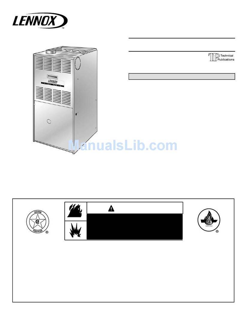
  9. Lennox SL297UHNV Series Installation and operation manual
Lennox SL297UHNV Series Installation and operation manual

Page 1 ©2021 Lennox Industries Inc.
Corp. 1802-L1
Revised 02/2021
SL297UHNV
Service Literature
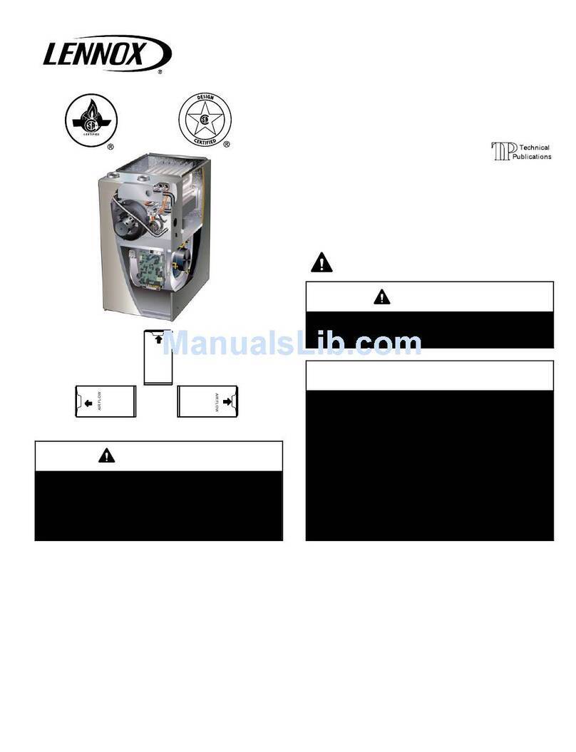
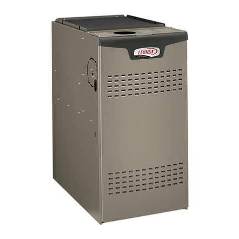
COMMUNICATING ENABLED SL297UHNV SERIES UNITS
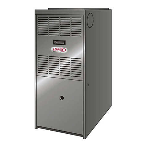
SL297UHNV series units are 90% efficiency gas furnaces
used for upflow or horizontal applications only.
SL297UHNV units are available in heating capacities of
40,000 to 80,000 Btuh and cooling applications up to 4
tons. Refer to Product Specifications Manual for proper siz
ing.
Units are factory equipped for use with natural gas.
SL297UHNV model units are equipped with a communicat
ing enabled SureLight®two-stage variable speed integrated
control. All units use a redundant gas valve to assure safety
shut-off as required by C.S.A.
All specifications in this manual are subject to change. Pro
cedures outlined in this manual are presented as a recom
mendation only and do not supersede or replace local or
state codes. In the absence of local or state codes, the
guidelines and procedures outlined in this manual (except
where noted) are recommendations only and do not consti
tute code.
TABLE OF CONTENTS
Specifications Page 2.............................
I Unit Components Page 11.......................
II Installation Page 33.............................
III Start Up Page 51..............................
IV Heating System Service Checks Page 52.........
V Typical Operating Characteristics Page 58.........
VI Maintenance Page 58..........................
VII Wiring and Sequence of Operation Page 61......
VIII Field Wiring and Jumper Settings Page 66.......
IX Program Unit Capacity Size Mode Page 70.......
X Troubleshooting Page 71........................
WARNING
Improper installation, adjustment, alteration, service
or maintenance can cause property damage, person
al injury or loss of life. Installation and service must
be performed by a licensed professional HVAC in
staller (or equivalent), service agency or the gas sup
plier.
CAUTION
As with any mechanical equipment, contact with
sharp sheet metal edges can result in personal in
jury. Take care while handling this equipment and
wear gloves and protective clothing.
Page 2
SPECIFICATIONS
Gas
Heating
Performance
Model No. SL297UH040NV36B SL297UH060NV36B
1AFUE 97.5% 97.5%
High
Fire
Input - Btuh 40,000 60,000
Output - Btuh 39,000 58,000
Temperature rise range - °F 30-60 50-80/25-55
Gas Manifold Pressure (in. w.g.)
Nat. Gas / LPG/Propane
3.5 3.5
Low
Fire
Input - Btuh 26,000 39,000
Output - Btuh 25,000 38,000
Temperature rise range - °F 20 - 50 25 - 55
Gas Manifold Pressure (in. w.g.)
Nat. Gas / LPG/Propane
1.5 1.5
High static - in. w.g. Heating 0.8 0.8
Cooling 1.0 1.0
Connections
in.
Intake / Exhaust Pipe (PVC) 2 / 2 2 / 2
Gas pipe size IPS 1/2 1/2
Condensate Drain Trap (PVC pipe) - i.d. 3/4 3/4
with furnished 90° street elbow 3/4 slip x 3/4 Mipt 3/4 slip x 3/4 Mipt
with eld supplied (PVC coupling) - o.d. 3/4 slip x 3/4 MPT 3/4 slip x 3/4 MPT
Indoor
Blower
Wheel nominal diameter x width - in. 10 x 9 10 x 9
Motor output - hp 1/2 1/2
Tons of add-on cooling 2 - 3 2 - 3
Air Volume Range - cfm 440-1370 475-1380
Electrical Data Voltage 120 volts - 60 hertz - 1 phase
Blower motor full load amps 7.7 7.7
Maximum overcurrent protection 15 15
Shipping Data lbs. - 1 package 125 130
NOTE - Filters and provisions for mounting are not furnished and must be eld provided.
1 Annual Fuel Utilization Efciency based on DOE test procedures and according to FTC labeling regulations. Isolated combustion system rating for non-weatherized
furnaces.
Gas
Heating
Performance
Model No. SL297UH080NV48C SL297UH080NV60C
1AFUE 97.5% 97.5%
High
Fire
Input - Btuh 80,000 80,000
Output - Btuh 78,000 78,000
Temperature rise range - °F 45-75 40-70
Gas Manifold Pressure (in. w.g.)
Nat. Gas / LPG/Propane
3.5 3.5
Low
Fire
Input - Btuh 52,000 52,000
Output - Btuh 51,000 51,000
Temperature rise range - °F 30 - 60 25 - 55
Gas Manifold Pressure (in. w.g.)
Nat. Gas / LPG/Propane
1.5 1.5
High static - in. w.g. Heating 0.8 0.8
Cooling 1.0 1.0
Connections
in.
Intake / Exhaust Pipe (PVC) 2 / 2 2 / 2
Gas pipe size IPS 1/2 1/2
Condensate Drain Trap (PVC pipe) - i.d. 3/4 3/4
with furnished 90° street elbow 3/4 slip x 3/4 Mipt 3/4 slip x 3/4 Mipt
with eld supplied (PVC coupling) - o.d. 3/4 slip x 3/4 MPT 3/4 slip x 3/4 MPT
Indoor
Blower
Wheel nominal diameter x width - in. 11 x 11 11 x 11
Motor output - hp 3/4 1
Tons of add-on cooling 2.5 - 4 3 - 5
Air Volume Range - cfm 620-1730 870-2285
Electrical Data Voltage 120 volts - 60 hertz - 1 phase
Blower motor full load amps 10.1 12.8
Maximum overcurrent protection 15 15
Shipping Data lbs. - 1 package 154 156
NOTE - Filters and provisions for mounting are not furnished and must be eld provided.
1 Annual Fuel Utilization Efciency based on DOE test procedures and according to FTC labeling regulations. Isolated combustion system rating for non-weatherized
furnaces.
Page 3
OPTIONAL ACCESSORIES - ORDER SEPARATELY
NOTE - FURNACES CANNOT BE TWINNED!
“B” Width
Models
“C” Width
Models
CABINET ACCESSORIES
Horizontal Suspension Kit - Horizontal only 51W10 51W10
Return Air Base - Upow only 50W98 50W99
High Performance Economizer (Commercial Only) 10U53 10U53
CONDENSATE DRAIN KITS
Condensate Drain Heat Cable 6 ft. 26K68 26K68
24 ft. 26K69 26K69
Crawl Space Vent Drain Kit US 51W18 51W18
Canada 15Z70 15Z70
CONTROLS
iComfort®Communicating Thermostat 12U67 12U67
iComfort Wi-Fi®Thermostat 10F81 10F81
1Remote Outdoor Air Temperature Sensor
(for dual fuel and Humiditrol®)
X2658 X2658
2Discharge Air Temperature Sensor 88K38 88K38
ComfortSense®7500 Thermostat 13H14 13H14
3Remote Outdoor Temperature Sensor
(for dual fuel and Humiditrol)
X2658 X2658
FILTER KITS
4Air Filter and
Rack Kit
Horizontal (end) Size of lter - in. 87L96 - 18 x 25 x 1 87L97 - 20 x 25 x 1
Side Return Single 44J22 44J22
Ten Pack 66K63 66K63
Size of lter - in. 16 x 25 x 1 16 x 25 x 1
Page 4
BLOWER DATA
SL297UH040NV36B BLOWER PERFORMANCE (less lter)
BOTTOM RETURN AIR
0 through 0.8 in. w.g. (Heating) and 0 through 1.0 in. w.g. (Cooling) External Static Pressure Range
HEATING
1Heating Speed
DIP Switch
Settings
First Stage Heating Speed - cfm Second Stage Heating Speed - cfm
+24% 1151 1153
+18% 1101 1099
+12% 816 1041
+6% 771 999
Factory Default 704 944
–6% 651 887
–12% 578 826
–18% 542 757
COOLING
1Cooling Speed
DIP Switch
Settings
First Stage Cooling Speed - cfm Second Stage Cooling Speed - cfm
Low Medium-Low Medium-High 2High Low Medium-Low Medium-High 2High
+ 549 732 862 970 907 1072 1233 1373
Factory Default 521 637 760 873 830 975 1117 1268
– 441 560 684 784 736 874 1014 1142
SL297UH040NV36B BLOWER PERFORMANCE (less lter)
SINGLE SIDE RETURN AIR
0 through 0.8 in. w.g. (Heating) and 0 through 1.0 in. w.g. (Cooling) External Static Pressure Range
HEATING
1Heating Speed
DIP Switch
Settings
First Stage Heating Speed - cfm Second Stage Heating Speed - cfm
+24% 863 1129
+18% 807 1087
+12% 761 1021
+6% 713 775
Factory Default 716 723
–6% 683 686
–12% 589 599
–18% 562 558
COOLING
1Cooling Speed
DIP Switch
Settings
First Stage Cooling Speed - cfm Second Stage Cooling Speed - cfm
Low Medium-Low Medium-High 2High Low Medium-Low Medium-High 2High
+ 554 705 841 958 868 1057 1217 1344
Factory Default 509 606 724 875 799 969 1109 1253
– 436 559 675 754 703 860 1002 1137
1 Cooling and heating speeds are based on a combination of DIP switch settings on the furnace control. Refer to Installation Instructions for specic DIP Switch Settings.
2 Factory default setting.
NOTES - The effect of static pressure is included in air volumes shown.
First stage HEAT is approximately 91% of the same second stage HEAT.
First stage COOL (two-stage air conditioning units only) is approximately 70% of the same second stage COOL speed position.
Continuous Fan Only speed is selectable at 28%, 38%, 70% and 100% of the selected second stage cooling speed - minimum 250 cfm.
Lennox iHarmony® Zoning System Applications - Minimum blower speed is 250 cfm.
Page 5
BLOWER DATA
SL297UH040NV36B BLOWER PERFORMANCE (less lter)
SINGLE SIDE RETURN AIR WITH OPTIONAL RETURN AIR BASE
0 through 0.8 in. w.g. (Heating) and 0 through 1.0 in. w.g. (Cooling) External Static Pressure Range
HEATING
1Heating Speed
DIP Switch
Settings
First Stage Heating Speed - cfm Second Stage Heating Speed - cfm
+24% 886 905
+18% 825 859
+12% 802 819
+6% 769 770
Factory Default 688 736
–6% 634 678
–12% 635 605
–18% 547 553
COOLING
1Cooling Speed
DIP Switch
Settings
First Stage Cooling Speed - cfm Second Stage Cooling Speed - cfm
Low Medium-Low Medium-High 2High Low Medium-Low Medium-High 2High
+ 542 698 835 947 886 1034 1201 1320
Factory Default 462 634 735 855 808 949 1096 1248
– 413 534 678 779 734 868 987 1130
SL297UH060NV36B BLOWER PERFORMANCE (less lter)
BOTTOM RETURN AIR
0 through 0.8 in. w.g. (Heating) and 0 through 1.0 in. w.g. (Cooling) External Static Pressure Range
HEATING
1Heating Speed
DIP Switch
Settings
First Stage Heating Speed - cfm Second Stage Heating Speed - cfm
+24% 1106 1234
+18% 1047 1158
+12% 989 1110
+6% 940 1054
Factory Default 886 999
–6% 837 947
–12% 780 882
–18% 722 826
COOLING
1Cooling Speed
DIP Switch
Settings
First Stage Cooling Speed - cfm Second Stage Cooling Speed - cfm
Low Medium-Low Medium-High 2High Low Medium-Low Medium-High 2High
+611 739 843 949 879 1046 1212 1380
Factory Default 554 681 783 883 816 952 1107 1254
– 486 630 712 802 739 876 1006 1132
1 Cooling and heating speeds are based on a combination of DIP switch settings on the furnace control. Refer to Installation Instructions for specic DIP Switch Settings.
2 Factory default setting.
NOTES - The effect of static pressure is included in air volumes shown.
First stage HEAT is approximately 91% of the same second stage HEAT.
First stage COOL (two-stage air conditioning units only) is approximately 70% of the same second stage COOL speed position.
Continuous Fan Only speed is selectable at 28%, 38%, 70% and 100% of the selected second stage cooling speed - minimum 250 cfm.
Lennox iHarmony® Zoning System Applications - Minimum blower speed is 250 cfm.
Page 6
BLOWER DATA
SL297UH060NV36B BLOWER PERFORMANCE (less lter)
SINGLE SIDE RETURN AIR
0 through 0.8 in. w.g. (Heating) and 0 through 1.0 in. w.g. (Cooling) External Static Pressure Range
HEATING
1Heating Speed
DIP Switch
Settings
First Stage Heating Speed - cfm Second Stage Heating Speed - cfm
+24% 1114 1237
+18% 1063 1168
+12% 1010 1106
+6% 951 1064
Factory Default 892 1003
–6% 837 942
–12% 761 869
–18% 693 809
COOLING
1Cooling Speed
DIP Switch
Settings
First Stage Cooling Speed - cfm Second Stage Cooling Speed - cfm
Low Medium-Low Medium-High 2High Low Medium-Low Medium-High 2High
+ 599 749 867 981 892 1057 1229 1404
Factory Default 549 656 754 866 775 958 1115 1279
– 475 609 680 773 708 854 1011 1147
SL297UH060NV36B BLOWER PERFORMANCE (less lter)
SINGLE SIDE RETURN AIR WITH OPTIONAL RETURN AIR BASE
0 through 0.8 in. w.g. (Heating) and 0 through 1.0 in. w.g. (Cooling) External Static Pressure Range
HEATING
1Heating Speed
DIP Switch
Settings
First Stage Heating Speed - cfm Second Stage Heating Speed - cfm
+24% 1098 1229
+18% 1039 1168
+12% 992 1104
+6% 930 1051
Factory Default 885 996
–6% 822 937
–12% 773 878
–18% 717 817
COOLING
1Cooling Speed
DIP Switch
Settings
First Stage Cooling Speed - cfm Second Stage Cooling Speed - cfm
Low Medium-Low Medium-High 2High Low Medium-Low Medium-High 2High
+ 578 746 847 957 889 1042 1197 1364
Factory Default 556 665 764 864 799 949 1093 1249
– 485 593 706 783 721 845 988 1122
1 Cooling and heating speeds are based on a combination of DIP switch settings on the furnace control. Refer to Installation Instructions for specic DIP Switch Settings.
2 Factory default setting.
NOTES - The effect of static pressure is included in air volumes shown.
First stage HEAT is approximately 91% of the same second stage HEAT.
First stage COOL (two-stage air conditioning units only) is approximately 70% of the same second stage COOL speed position.
Continuous Fan Only speed is selectable at 28%, 38%, 70% and 100% of the selected second stage cooling speed - minimum 250 cfm.
Lennox iHarmony® Zoning System Applications - Minimum blower speed is 250 cfm.
Page 7
BLOWER DATA
SL297UH080NV48C BLOWER PERFORMANCE (less lter)
BOTTOM RETURN AIR
0 through 0.8 in. w.g. (Heating) and 0 through 1.0 in. w.g. (Cooling) External Static Pressure Range
HEATING
1Heating Speed
DIP Switch
Settings
First Stage Heating Speed - cfm Second Stage Heating Speed - cfm
+24% 1499 1640
+18% 1427 1546
+12% 1361 1472
+6% 1294 1399
Factory Default 1219 1315
–6% 1176 1242
–12% 1090 1173
–18% 1007 1077
COOLING
1Cooling Speed
DIP Switch
Settings
First Stage Cooling Speed - cfm Second Stage Cooling Speed - cfm
Low Medium-Low Medium-High 2High Low Medium-Low Medium-High 2High
+ 797 954 1071 1241 1102 1304 1508 1713
Factory Default 713 873 969 1147 1006 1186 1392 1588
– 623 767 880 1025 911 1068 1252 1422
SL297UH080NV48C BLOWER PERFORMANCE (less lter)
SINGLE SIDE RETURN AIR
0 through 0.8 in. w.g. (Heating) and 0 through 1.0 in. w.g. (Cooling) External Static Pressure Range
HEATING
1Heating Speed
DIP Switch
Settings
First Stage Heating Speed - cfm Second Stage Heating Speed - cfm
+24% 1433 1542
+18% 1353 1480
+12% 1275 1398
+6% 1229 1334
Factory Default 1154 1253
–6% 1093 1181
–12% 1024 1107
–18% 958 1054
COOLING
1Cooling Speed
DIP Switch
Settings
First Stage Cooling Speed - cfm Second Stage Cooling Speed - cfm
Low Medium-Low Medium-High 2High Low Medium-Low Medium-High 2High
+ 792 959 1118 1264 1104 1302 1530 1730
Factory Default 844 876 1008 1162 1001 1202 1397 1612
– 643 771 908 1055 915 1090 1253 1443
1 Cooling and heating speeds are based on a combination of DIP switch settings on the furnace control. Refer to Installation Instructions for specic DIP Switch Settings.
2 Factory default setting.
NOTES - The effect of static pressure is included in air volumes shown.
First stage HEAT is approximately 91% of the same second stage HEAT.
First stage COOL (two-stage air conditioning units only) is approximately 70% of the same second stage COOL speed position.
Continuous Fan Only speed is selectable at 28%, 38%, 70% and 100% of the selected second stage cooling speed - minimum 380 cfm.
Lennox iHarmony® Zoning System Applications - Minimum blower speed is 380 cfm.
Page 8
BLOWER DATA
SL297UH080NV48C BLOWER PERFORMANCE (less lter)
SINGLE SIDE RETURN AIR WITH OPTIONAL RETURN AIR BASE
0 through 0.8 in. w.g. (Heating) and 0 through 1.0 in. w.g. (Cooling) External Static Pressure Range
HEATING
1Heating Speed
DIP Switch
Settings
First Stage Heating Speed - cfm Second Stage Heating Speed - cfm
+24% 1,407 1,528
+18% 1,342 1,461
+12% 1,283 1,388
+6% 1,217 1,304
Factory Default 1,152 1,237
–6% 1,080 1,150
–12% 1,015 1,114
–18% 953 1,038
COOLING
1Cooling Speed
DIP Switch
Settings
First Stage Cooling Speed - cfm Second Stage Cooling Speed - cfm
Low Medium-Low Medium-High 2High Low Medium-Low Medium-High 2High
+ 831 969 1103 1269 1096 1323 1541 1731
Factory Default 753 905 1008 1150 1005 1208 1385 1605
– 806 807 932 1045 920 1102 1269 1451
SL297UH080NV60C BLOWER PERFORMANCE (less lter)
BOTTOM RETURN AIR
0 through 0.8 in. w.g. (Heating) and 0 through 1.0 in. w.g. (Cooling) External Static Pressure Range
HEATING
1Heating Speed
DIP Switch
Settings
First Stage Heating Speed - cfm Second Stage Heating Speed - cfm
+24% 1591 2135
+18% 1503 2026
+12% 1426 1921
+6% 1334 1828
Factory Default 1277 1716
–6% 1197 1609
–12% 1124 1504
–18% 1037 1402
COOLING
1Cooling Speed
DIP Switch
Settings
First Stage Cooling Speed - cfm Second Stage Cooling Speed - cfm
Low Medium-Low Medium-High 2High Low Medium-Low Medium-High 2High
+ 1094 1253 1388 1580 1584 1825 2065 2286
Factory Default 984 1155 1284 1445 1454 1659 1881 2092
– 868 1021 1152 1302 1301 1490 1693 1890
1 Cooling and heating speeds are based on a combination of DIP switch settings on the furnace control. Refer to Installation Instructions for specic DIP Switch Settings.
2 Factory default setting.
NOTES - The effect of static pressure is included in air volumes shown.
First stage HEAT is approximately 91% of the same second stage HEAT.
First stage COOL (two-stage air conditioning units only) is approximately 70% of the same second stage COOL speed position.
Continuous Fan Only speed is selectable at 28%, 38%, 70% and 100% of the selected second stage cooling speed - minimum 450 cfm.
Lennox iHarmony® Zoning System Applications - Minimum blower speed is 250 for 080NV48C and 450 cfm for 080NV60C.
Page 9
BLOWER DATA
SL297UH080NV60C BLOWER PERFORMANCE (less lter)
SINGLE SIDE RETURN AIR - Air volumes in bold require Optional Return Air Base and eld fabricated transition to accommodate
20 x 25 x 1 in. cleanable air lter in order to maintain proper air velocity across the lter.
0 through 0.8 in. w.g. (Heating) and 0 through 1.0 in. w.g. (Cooling) External Static Pressure Range
HEATING
1Heating Speed
DIP Switch
Settings
First Stage Heating Speed - cfm Second Stage Heating Speed - cfm
+24% 1491 2027
+18% 1414 1901
+12% 1351 1801
+6% 1284 1722
Factory Default 1211 1621
–6% 1130 1517
–12% 1048 1407
–18% 993 1323
COOLING
1Cooling Speed
DIP Switch
Settings
First Stage Cooling Speed - cfm Second Stage Cooling Speed - cfm
Low Medium-Low Medium-High 2High Low Medium-Low Medium-High 2High
+ 1094 1279 1430 1609 1599 1823 2051 2239
Factory Default 1003 1160 1308 1454 1438 1649 1863 2097
– 894 1044 1166 1309 1301 1490 1683 1897
1 Cooling and heating speeds are based on a combination of DIP switch settings on the furnace control. Refer to Installation Instructions for specic DIP Switch Settings.
2 Factory default setting.
NOTES - The effect of static pressure is included in air volumes shown.
First stage HEAT is approximately 91% of the same second stage HEAT.
First stage COOL (two-stage air conditioning units only) is approximately 70% of the same second stage COOL speed position.
Continuous Fan Only speed is selectable at 28%, 38%, 70% and 100% of the selected second stage cooling speed - minimum 450 cfm.
Lennox iHarmony® Zoning System Applications - Minimum blower speed is 450 cfm.
Page 10
FIGURE 1
Heat Exchanger
Gas Valve
Combustion
Air Inducer
Indoor Blower
Two-Stage Control
Cabinet
Panel
Inner Panel
Gas Pipe Inlet
(right side only)
Inlet Vent Pipe
Exhaust Vent Pipe
Exhaust Coupling
Intake Air Assembly
Rollout Switch
Burner Assembly
Page 11
I-UNIT COMPONENTS
SL297UHNV unit components are shown in figure 1. The
gas valve, combustion air inducer and burners can be ac
cessed by removing the access panel. Electrical compo
nents are in the control box (figure 2) found in the blower
section.
SL297UHNV units are factory equipped with a bottom return
air panel in place. The panel is designed to be field removed
as required for bottom air return. Markings are provided for
side return air and may be cut out in the field.
CAUTION
Electrostatic discharge can affect elec
tronic components. Take precautions
to neutralize electrostatic charge by
touching your hand and tools to metal
prior to handling the control.
A- Control Box
1. Control Transformer (T1)
A transformer located in the control box provides power to
the low voltage section of the unit. Transformers on all
models are rated 40VA with a 120V primary and a 24V sec
ondary.
2. Door Interlock Switch (S51)
A door interlock switch rated 14A at 125VAC is wired in se
ries with line voltage. When the inner blower access panel
is removed the unit will shut down.
FIGURE 2
CONTROL BOX SL297UHNV
Transformer
SureLight®Integrated Control
Interlock Switch
Circuit Breaker
3. Circuit Breaker (CB8)
A 24V circuit breaker is also located in the control box.
The switch provides overcurrent protection to the trans
former (T1). The breaker is rated 3A at 32V. If the current
exceeds this limit the breaker will trip and all unit opera
tion will shutdown. The breaker can be manually reset
by pressing the button on the face. See figure 3.
FIGURE 3
CIRCUIT BREAKER CB8
PRESS TO RESET
WARNING
Shock hazard.
Disconnect power before servicing. Integrated
control is not field repairable. If control is inoper
able, simply replace entire control.
Can cause injury or death. Unsafe operation will re
sult if repair is attempted.
4. Integrated Control (A92)
Units are equipped with the iComfort®enabled Sur
eLight®two-stage, variable speed integrated control. This
control is used with the iComfort Wi-Fi®thermostat as part
of a communicating comfort system. The control can also
operate with a non-communicating conventional single or
two-stage thermostat. The system consists of a ignition /
blower control (figures 4 and 5) with control pin designa
tions in tables 1, 2 and 3 and ignitor. The control and ignitor
work in combination to ensure furnace ignition and ignitor
durability. The control provides gas ignition, safety checks
and indoor blower control with two-stage gas heating. The
furnace combustion air inducer, gas valve and indoor blow
er are controlled in response to various system inputs such
as thermostat signal, pressure and limit switch signal and
flame signal. The control features a seven-segment LED
display, indicating furnace status (including indoor blower)
and error codes. The LED flashes in single digits. For ex
ample using table 5 under LIMIT CODE, an “E” followed by
“2” followed by “5” followed by “0”, the limit switch circuit is
open. The control also has two unpowered (dry) 1/4” con
tacts for a humidifier and a 120 volt accessory terminal.
Both rated at (1) one amp each.
Electronic Ignition
At the beginning of the heat cycle the integrated control
monitors the first stage and second stage combustion air
inducer prove switch. The control will not begin the heating
cycle if the first stage prove switch is closed (by-passed).
Likewise the integrated control will not begin the second
stage heating cycle if the second stage prove switch is
closed, and will remain in first stage heat. However, if the
second stage prove switch closes during the first stage
heat pre-purge, the control will allow second stage heat.
Once the first stage prove switch is determined to be open,
Page 12
the combustion air inducer is energized on low (first stage)
heat speed. When the differential in the prove switch is
great enough, the prove switch closes and a 15-second
pre-purge begins.
NOTE - During abnormal conditions such as low supply
voltage or low outdoor temperatures and the low fire pres
sure switch does not close, the combustion air inducer will
switch to high fire. After a 15 second pre-purge the high fire
pressure switch will close and the unit will begin operation
on high fire. After 10 to 20 seconds of high fire operation the
unit will switch to low fire
After the 15-second pre-purge period, the SureLight®igni
tor warms up for 20 seconds after which the gas valve
opens for a 4-second trial for ignition. The ignitor remains
energized during the trial until flame is sensed. If ignition is
not proved during the 4-second period, the control will try
four more times with an inter purge and warm-up time be
tween trials of 35 seconds. After a total of five trials for igni
tion (including the initial trial), the control goes into Watch
guard-Flame Failure mode. After a 60-minute reset period,
the control will begin the ignition sequence again.
Two Stage Operation / Thermostat Selection DIP
Switch
The control can be utilized in two modes: SINGLE-STAGE
thermostat or TWO-STAGE thermostat. The thermostat
selection is made using a DIP switch and must be posi
tioned for the particular application. DIP switch 1, labeled
T”STAT HEAT STAGE is factory-set in the OFF position for
use with a two-stage thermostat. Move the DIP switch to
ON for use with a single stage thermostat.
While in the single-stage thermostat mode, the burners will
always fire on first-stage heat. The combustion air inducer
will operate on low speed and indoor blower will operate on
low heat speed. The unit will switch to second stage heat
after a "recognition period". DIP switch 2, labeled SECOND
STAGE DELAY, is factory set in the OFF position for a 7
minute recognition period. The switch can be moved to the
ON position for a 12 minute recognition period, after which
time the unit will switch to secondstage heat. While in the
two-stage thermostat mode, the burners will fire on first-
stage heat. The combustion air inducer will operate on low
speed and indoor blower will operate on low heat speed.
The unit will switch to second-stage heat on call from the
indoor thermostat. If there is a simultaneous call for first
and second stage heat, the unit will fire an first stage heat
and switch to second stage heat after 30 seconds of opera
tion. See Sequence of Operation flow charts in the back of
this manual for more detail.
TABLE 1
SureLight
®
Control 5 Pin Terminal Designation
PIN # Function
1 Ignitor
2Combustion Air Inducer High Speed
3Combustion Air Inducer Low Speed
4Combustion Air Inducer Neutral
5Ignitor Neutral
TABLE 2
SureLight
®
Control 12 Pin Terminal Designation
PIN # Function
1Gas Valve Second Stage
2Second Stage Prove Switch
3Rollout Switch In
4 Ground
524V Hot
6Primary Limit In
7Gas Valve First Stage
8Gas Valve Common
924V Neutral
10 Ground
11 Rollout Switch Out
12 First Stage Prove Switch
TABLE 3
SureLight
®
Control 6 Pin Terminal Designation
PIN # Function
1Data Input From Motor
2 Common
3Not Used
4Data Output To Motor
55 Volt Bias Supply
6Not Used
Page 13
FIGURE 4
INTEGRATED CONTROL
THERMOSTAT CONNECTIONS (TB1)
1/4” QUICK CONNECT TERMINALS
TB83 icomforttCommunicating Outdoor Equipment
R = 24VAC
I + = DATA HIGH CONNECTION
I - = DATA LOW CONNECTION
C = 24VAXC COMMON
R = 24VAC
I + = DATA HIGH CONNECTION
I - = DATA LOW CONNECTION
C = 24VAXC COMMON
FLAME SENSE
DIP SWITCHES
OUTDOOR AIR
SENSOR
TERMINALS
DISCHARGE AIR
SENSOR
TERMINALS
INDOOR
BLOWER
CONNECTOR
NEUTRAL
DIAGNOSTIC
PUSH BUTTON
TB83
icomfortt
COMMUNICATING
OUTDOOR
EQUIPMENT
TB84
icomfortt
COMMUNICATING
INDOOR
THERMOSTAT
DS = DEHUMIDIFICATION SIGNAL
W2 = HEAT DEMAND FROM 2ND STAGE T/STAT
W1 = HEAT DEMAND FROM 1ST STAGE T/STAT
R = CLASS 2 VOLTAGE TO THERMOSTAT
G = MANUAL FAN FROM T'STAT
C = THERMOSTAT SIGNAL GROUND CONNECTED TO
TRANSFORMER GRD (TR) & CHASIS GROUND (GRD)
Y1 = THERMOSTAT 1ST STAGE COOL SIGNAL
Y2 = THERMOSTAT 2ND STAGE COOL SIGNAL
O = THERMOSTAT SIGNAL TO HEAT PUMP
REVERSING VALVE
L = USE ONLY WITH A COMMUNICATING THERMOSTAT
AND A NON-COMMUNICATING OUTDOOR UNIT
DH = DEHUMIDIFICATION OUTPUT COMMUNICATING
THERMOSTAT ONLY
HUM = UNPOWERED NORMALLY OPEN (DRY) CONTACTS
XMFR = 120 VAC OUTPUT TO TRANSFORMER
LI = 120 VAC INPUT TO CONTROL
ACC = 120 VAC OUTPUT TO OPTIONAL ACCESSORY
NEUTRALS = 120 VAC NEUTRAL
W915 Y1 TO Y2
2 STAGE COMPR
W951 R TO O
HEAT PUMP
W914 R TO DS
DEHUM OR
HARMONY
W1 W2 G Y2 Y1 CCRDHLODS
RI + I - CRI + I - C
7 SEGMENT LED
ACC
LINE 1
HUM
12 PIN LOW
VOLTAGE
CONNECTOR
NON-COMMUNICATING
24V TERMINALS
HS/ CAI
TB84 icomforttCommunicating Indoor Thermostat
Page 14
FIGURE 5
HEATING BLOWER−OFF DELAY
60 SECOND
HTG BLOWER
OFF DELAY
120 SECOND
HTG BLOWER
OFF DELAY
180 SECOND
HTG BLOWER
OFF DELAY
FLAME
15
HSI/CAI
2ND STAGE HEAT ON DELAY
7 MIN
UPSTAGE
DELAY
12 MIN
UPSTAGE
DELAY
*CONTINUOUS FAN MODE BLOWER SPEED
COOLING MODE BLOWER RAMPING
CLG BLOWER SPEED ADJUSTMENT
COOLING MODE BLOWER SPEED
W915
2 STAGE
COMPR
1−STG COMPRESSOR
2−STAGE
COMPRESSOR LINK
(JUMPERS Y1 to Y2)
W915
DO NOT CUT
2−STG COMPRESSOR
HEAT PUMP LINK
(JUMPERS R to O)
W951
DEHUMIDIFICATION−
HARMONY LINK
(JUMPERS R to DS)
W914
W915
2 STAGE
COMPR
CUT LINK
A/C UNIT
DO NOT CUT
HEAT PUMP UNIT
CUT LINK
W951
HEAT
PUMP
W951
HEAT
PUMP
W914
DEHUM
or
NO HARMONY ZONING
OR
NO SIGNATURESTAT
W/ DS CONNECTION
DO NOT CUT
HARMONY ZONING
OR
SIGNATURESTAT W/
DS CONNECTION
CUT LINK
HARMONY
W914
DEHUM
or
HARMONY
1
1
1
ON−BOARD LINK
OPTION SELECTION
1234567
1234567
123567
4
123567
4
NEUTRALS
L1
ACC
HUM
14
36
P79
110
312
J2
4 7
W915
2 STAGE
COMPR
W951
HEAT
PUMP
W914
DEHUM
HARMONY
CUT FOR
OPTION
SELECTION
OUTDOOR
SENSOR
DISCHARGE
AIR SENSOR
123456
10 12
911
13
ON
ON
SureLight
®
W1W2 GY2 Y1 C C DH L O DSR
W1
W2
G
Y2
Y1
C
C
R
L
DH
HIGH
SPEED
(100%)
MEDIUM−HIGH
SPEED
(70%)
MEDIUM−LOW
SPEED
(38%)
LOW
SPEED
(28%)
*
OPTION A
OFF−50%−82%−
100%−50%−OFF
OPTION B
OFF−82%−100%−OFF
OPTION C
OFF−100%−100%−OFF
OPTION D
OFF−100%−OFF
*
DEFAULT
+ 10%
−10%
*
HIGH
SPEED
MEDIUM−HIGH
SPEED
MEDIUM−LOW
SPEED
LOW
SPEED
*
7
−PROTECTIVE PLASTIC FILM ON DIP SWITCHES MAY BE
REMOVED FOR EASE IN SETTING OF DIP SW.
−CUT ON−BOARD LINK (SOLDER TRACE) COMPLETELY THROUGH
BOTH LAYERS ON THE CONTROL BOARD
−LINKS CUT IN ERROR −INSTALL A JUMPER ON THE APPROPRIATE
TERMINALS ON THE TERMINAL STRIP
1
9
10 11
12 13
14
ON
ON
ON
ON
ON
ON
ON
ON
90 SECOND
HTG BLOWER
OFF DELAY
*1234567
ON
1234567
ON
THERMOSTAT SELECTION
1−STAGE
THERMOSTAT
(TIMED STAGING)
−SEE SW #2
TWO STAGE
THERMOSTAT
*1234567
1234567
ON
ON
−BLOWER ON DELAY −30 SEC. FIXED
15
9
10 11
12 14 15
9
10 11
12 14 15
9
10 11
12 14 15
8
8
8
8
8
8
8
8
1234567
1234567
ON
ON
1234567
ON
1234567
ON
8
8
8
8
9
10 11
12 13
14
ON
ON
ON
ON
15
9
10 11
12 14 15
9
10 11
12 14 15
9
10 11
12 14 15
9
10 11
12 13
14
ON
ON
ON
ON
15
9
10 11
12 14 15
9
10 11
12 14 15
9
10 11
12 14 15
HEATING MODE BLOWER SPEED
1234567
ON
1234567
ON
1234567
ON
8
8
8
9
10 11
12 13
14
ON
ON
ON
ON
15
9
10 11
12 14 15
9
10 11
12 14 15
9
10 11
12 14 15
FACTORY
DEFAULT
+ 24%
+ 18%
+ 12%
+ 6%
−6%
−12%
−18%
8
14 15
INCREASE AIR HTG CFM
DECREASE AIR HTG CFM
SENSE
RI+ I−CRI+ I−C
OUTDOOR EQUIPMENT
I+ I−
INDOOR EQUIPMENT
IGN
CAI2
CAI1
N
N
J3
S1
S4S3
13
13
13
13
13
13
13
* FACTORY DEFAULT
13
13
*
DIAGNOSTIC
LED
DIAGNOSTIC
PUSH BUTTON
INTEGRATED CONTROL CONFIGURATION GUIDE
Page 15
TABLE 4
Integrated Control Diagnostic Modes
Display Action (when button released)
No change (idle)* Remain in idle mode
Solid “E” Enter diagnostic recall mode
Solid “F” Enter flame signal mode
Solid “D” Discharge Air Installed
Solid “P” (variable speed only) Program unit capacity/size (Unit Code)
__
Two horizontal bars __ Soft disable
* No change implies the display will continue to show whatever is currently being displayed for normal operation (blinking
decimal, active error code, heat state, etc.
Diagnostic LED (Figure 4)
The seven-segment diagnostic LED displays operating
status, target airflow, error codes and other information.
The table beginning on Page 16 lists diagnostic LED
codes.
Diagnostic Push Button (Figure 4)
The diagnostic push button is located adjacent to the
seven-segment diagnostic LED. This button is used to en
able the Error Code Recall “E” mode, the Flame Signal “F”
mode and “P” the Program Unit Capacity/Size mode. Press
the button and hold it to cycle through a menu of options.
Every five seconds a new menu item will be displayed.
When the button is released, the displayed item will be se
lected. Once all items in the menu have been displayed, the
menu resumes from the beginning until the button is re
leased.
Error Code Recall Mode
Select ”E” from the menu to access the most recent 10 error
codes. Select “c” from the Error Code Recall menu to clear
all error codes. Button must be pressed a second time
while “c” is flashing to confirm command to delete codes.
Press the button until a solid “≡” is displayed to exit the Error
Code Recall mode.
Flame Signal Mode
Select ”F” from the menu to access the flame signal mode.
The integrated control will display the flame current on
seven-segment LED in in micro amps (uA).
Flame signal mode is exited after any of the following:
Power is reset
Pressing and holding push button until 3 horizontal
lines “≡” are displayed
10 minutes after entering the flame sense mode.
Program Unit Capacity/Size Mode
After the “P” is selected (by releasing the push button) the
integrated control will start flashing the “P” on display for 90
seconds. If push button is pressed again and held during
that time, the control will start to display characters corre
sponding to different variable speed furnace models for 3
seconds each. While the wanted character-model is dis
played push button has to be released. Selected option will
flash display for 10 seconds and during that time push but
ton has to be pressed and held for 5 seconds. Once control
accepts new setting it will store data in non-volatile memory
and reset itself. If 10 seconds expires or push button is held
less than 5 seconds, control will exit field test mode and go
into idle without changing programming the unit size.
Soft Disable
Soft disabling is when thermostat finds a device on the BUS
that it does not recognize and the thermostat sends a the
device a message to be in soft disabling mode until proper
ly configured. Two horizontal bars will display.
Steps to follow if the damper control module is displaying
the soft disable code.
1- Confirm proper wiring between all devices (thermo
stat, damper control module, indoor and outdoor).
2- Cycle power to the control that is displaying the soft
disable code.
3- Put the room thermostat through set up.
4- Go to setup / system devices / thermostat / edit /
then push reset.
5- Go to setup / system devices / thermostat / edit /
then push resetAll.
Page 16
TABLE 5
Integrated Diagnostic Codes/Status of Equipment
Code Diagnostic Codes/Status of Equipment Action Required to Clear and Recover
.Idle mode (Decimal blinks at 1 Hertz -- 0.5 second ON, 0.5 second OFF).
ACubic feet per minute (cfm) setting for indoor blower (1 second ON, 0.5
second OFF) / cfm setting for current mode displayed.
CCooling stage (1 second ON, 0.5 second OFF) / 1 or 2 displayed / Pause
/ cfm setting displayed / Pause / Repeat codes).
dDehumidification mode (1 second ON) / 1 second OFF) / cfm setting dis
played / Pause / Repeat Codes).
hHeat pump stage (1 second ON, 0.5 second OFF) / % of input rate dis
played / Pause / cfm setting / Pause / Repeat codes.
HGas Heat Stage (1 second ON, 0.5 second OFF) / 1 or 2 displayed /
Pause / cfm
setting displayed / Pause / Repeat codes. Blinking during ignition.
dF Defrost mode.
UDischarge Air Temperature
E 105 Device communication problem - No other devices on RS BUS (Commu
nication
system).
Equipment is unable to communicate. Indicates
numerous message errors. In most cases errors are
related to electrical noise. Make sure high voltage
power is separated from RSBus. Check for mis-
wired and/or loose connections between the stat,
indoor unit and outdoor unit. Check for a high volt
age source of noise close to the system. Fault
clears after communication is restored.
E 110 Low line voltage. Line Voltage Low (Voltage lower than nameplate
rating). Check power line voltage and correct. Alarm
clears 5 seconds after fault recovered.
E 111 Line voltage polarity reversed. Reverse line power voltage wiring. System resumes
normal operation 5 seconds after fault recovered.
E 112 Ground not detected System shuts down. Provide proper earth ground.
System resumes normal operation 5 seconds after
fault recovered.
E 113 High line voltage. Line Voltage High (Voltage higher than nameplate
rating). Provide power voltage within proper range.
System resumes normal operation 5 seconds after
fault recovered.
E 114 Line voltage frequency out-of-range. No 60 Hertz Power. Check voltage and line power
frequency. Correct voltage and frequency problems.
System resumes normal operation 5 seconds after
fault recovered.
E 115 Low 24V - Control will restart if the error recovers. 24-Volt Power Low (Range is 18 to 30 volts). Check
and correct voltage. Check for additional power-rob
bing equipment connected to system. May require
installation of larger VA transformer to be installed
in furnace / air handler. Clears after fault recovered.
E 116 High 24V. 24 Volt Power High (Range is 18 to 30 volts). Check
and correct voltage. Check for proper line voltage
(120V, 240V, etc.) to equipment. Clears when con
trol senses proper voltage.
E 117 Poor ground detected (Warning only) Provide proper grounding for unit. Check for proper
earth ground to the system. Warning only will clear
30 seconds after fault recovered.
E 120 Unresponsive device. Communication only. Usually caused by delay in outdoor unit responding
to indoor unit poling. Recycle power. Check all wir
ing connections. Cleared after unresponsive device
responds to any inquiry.
Page 17
TABLE 5 Continued
Code Diagnostic Codes/Status of Equipment Action Required to Clear and Recover
E 124 Active communicating thermostat signal missing for more than 3 min
utes.
Equipment lost communication with the thermostat.
Check four wiring connections, ohm wires and cycle
power at the thermostat. Alert stops all services and
waits for heartbeat message from thermostat (sub
net controller). Cleared after valid thermostat (sub
net controller) message is received.
E 125 Control failed self-check, internal error, failed hardware. Will restart if
error
recovers. Integrated control not communicating. Covers hardware errors
(flame sense circuit faults, pin shorts, etc.).
Hardware problem on the control. Cycle power on
control. Replace if problem prevents service and is
persistent. Critical alert. Cleared 300 seconds after
fault recovered.
E 126 Control internal communication problem. Hardware problem on the control. Cycle power on
control. Replace if problem prevents service and is
persistent. Cleared 300 seconds after fault recov
ered.
E 131 Corrupted control parameters (Verify configuration of system). Communi
cating only.
Reconfigure the system. Replace control if heating
or cooling is not available. Only applicable in the
communicating mode, not in startup. Exit from Com
missioning and Execute 'Set Factory Default mode'.
Control will still operate on default parameter set
tings.
E 180 Outdoor air temperature sensor failure. Only shown if shorted or out-of-
range.
Compare outdoor sensor resistance to temperature/
resistance charts in unit installation instructions.
Replace sensor pack if necessary. At beginning of
(any) configuration, furnace or air handler control
will sense outdoor air and discharge air temperature
sensor(s). If detected (reading in range), appropri
ate feature will be set as 'installed' and that could be
seen in 'About' screen. In normal operation after
control recognizes sensors, alarm will be sent if
valid temperature reading is lost. To get rid of set
ting and alarm, redo configuration and make sure
that temperature sensor is marked as 'not installed'
in Indoor Unit 'About' screen. When Indoor unit con
trol is replaced, thermostat will 'tell' new control if
temperature sensor is in system or not. Clears 30
seconds after fault recovered.
E 200 Hard lockout - Rollout circuit open or previously open. Correct cause of rollout trip, or replace flame rollout
switch. Test furnace operation. Cleared after fault
recovered.
E 201 Indoor blower communication failure - Unable to communicate with blow
er motor.
Indoor blower communication failure (including pow
er outage). Lost communication with indoor blower
motor. Possible causes: motor not powered, loose
wiring. Problem may be on control or motor side.
Cleared after fault recovered.
E 202 Indoor blower motor mis-match - Indoor motor horsepower does not
match unit capacity. See Page 70.
Incorrect appliance capacity code selected. Check
for proper configuring under: Unit Size Codes for
Furnace/Air Handler on configuration guide or in
installation instructions. Cleared after the correct
match is detected following a reset. (Remove ther
mostat from system while applying power and re
programming.)
E 203 Appliance capacity / size is NOT programmed. Invalid unit codes refer to
configuration flow chart. See Page 70.
No appliance capacity code selected. Check for
proper configuring under: Unit Size Codes for Fur
nace on configuration guide or in installation instruc
tions. Critical Alert. Cleared after valid unit code is
read following a reset. (Remove thermostat from
system while applying power and reprogramming.)
E 204 Gas valve mis-wired. Check gas valve operation and wiring. Clears when
repaired.
E 205 Gas valve control relay contact shorted. Check wiring on control and gas valve. If wiring is
correct, replace control.
Page 18
TABLE 5 Continued
Code Diagnostic Codes/Status of Equipment Action Required to Clear and Recover
E 206 Gas valve second-stage relay failure Furnace will operate on 1s
t
stage for remainder of
the heating demand. Will clear after fault recovered.
If unable to operate 2nd stage, replace control.
E 207 Hot surface ignitor sensed open Measure resistance of hot surface ignitor. Replace if
open or not within specified range found in IOM.
Resumes normal operation after fault is cleared.
E 223 Low pressure switch failed open. Check pressure (inches w.c.) of low pressure switch
closing on heat call. Measure operating pressure
(inches w.c.). Inspect vent and combustion air in
ducer for correct operation and restriction. Re
sumes normal operation after fault is cleared
E 224 Low pressure switch failed closed. Check operation of low pressure switch to see if it is
stuck closed on heat call longer than 150 seconds.
Measure operating pressure (inches w.c.). Inspect
vent and combustion air inducer for correct opera
tion and restriction. Resumes normal operation after
fault is cleared.
E 225 High pressure switch failed open. Check pressure (inches w.c.) of high pressure
switch closing on heat call. Measure operating pres
sure (inches w.c.). Inspect vent and combustion air
inducer for correct operation and restriction. Re
sumes normal operation after fault is cleared.
E 226 High pressure switch failed closed. Check operation of high pressure switch closing on
heat call. Measure operating pressure (inches w.c.).
Inspect vent and combustion air inducer for correct
operation and restriction. Resumes normal opera
tion after fault is cleared.
E 227 Low pressure switch open during trial for ignition or run mode. Check pressure (inches w.c.) of low pressure switch
closing on heat call. Measure operating pressure
(inches w.c.). Inspect vent and combustion air in
ducer for correct operation and restriction. Re
sumes normal operation after fault is cleared.
E 228 Combustion air inducer calibration failure Unable to perform pressure switch calibration.
Check vent system and pressure switch wiring con
nections. Resumes normal operation after fault is
cleared.
E 229 Ignition on High Fire - Information Only Code is displayed if 1) low pressure switch fails to
close, then furnace will switch to high speed inducer
to close both low and high pressure switches, then
furnace lights on high fire, or 2) if continuous fan is
active, furnace lights on high fire for 60 seconds to
improve heat exchanger warm up time.
E 240 Low flame current - Run mode. Check micro-amperes of flame sensor using control
diagnostics or field-installed mode. Clean or replace
sensor. Measure voltage of neutral to ground to
ensure good unit ground. Alert clears after current
heat call has been completed.
E 241 Flame sensed out of sequence - Flame still present. Shut off gas. Check for gas valve leak. Replace, if
necessary. Alert clears when fault is recovered.
E 250 Limit switch circuit open. Check for proper firing rate on furnace. Ensure
there is no blockage in heater. Check for proper air
flow. If limit not closed within 3 minutes, unit will go
into 1-hour soft lockout. Resumes normal operation
after fault is cleared.
E 252 Discharge air temperature too high (gas heat only). Check temperature rise, air flow and input rate.
Cleared when heat call is finished.
E 270 Soft lockout - Exceeded maximum number of retries. No flame current
sensed.
Check for proper gas flow. Ensure that ignitor is
lighting burner. Check flame sensor current. Clears
when heat call finishes successfully.
Page 19
TABLE 5 Continued
Code Diagnostic Codes/Status of Equipment Action Required to Clear and Recover
E 271 Soft lockout - Exceeded maximum number of retries. Last retry failed due
to the pressure switch opening.
Check pressure (inches w.c.) of low pressure switch
closing on heat call. Measure operating pressure
(inches w.c.). Inspect vent and combustion air in
ducer for correct operation and restriction. Clears
when heat call finishes successfully.
E 272 Soft lockout - Exceeded maximum number of recycles. Last recycle due
to the pressure switch opening.
Check operation of low pressure switch to see if it is
stuck closed on heat call. Check pressure (inches
w.c.) of high pressure switch closing on heat call.
Measure operating pressure (inches w.c.). Inspect
vent and combustion air inducer for correct opera
tion and restriction. Clears when heat call finishes
successfully.
E 273 Soft lockout - Exceeded maximum number of recycles. Last recycle due
to flame failure.
Check micro-amperes of flame sensor using control
diagnostics or field-installed mode. Clean or replace
sensor. Measure voltage of neutral to ground to
ensure good unit ground. Clears when heat call
finishes successfully.
E 274 Soft lockout - Exceeded maximum number of recycles. Last recycle
failed due to the limit circuit opening or limit remained open longer than
3 minutes.
Shut down system. 1-hour soft lockout. Check firing
rate and air flow. Check for blockage. Clears when
heat call finishes successfully.
E 275 Soft lockout - Flame sensed out of sequence. Flame signal is gone. Shut off gas. Check for gas valve leak. 1-hour soft
lockout. Clears when flame has been proven stable.
E 276 Watchguard calibration failure. Unable to perform pressure switch calibration.
Check vent system and pressure switch wiring con
nections. 1-hour soft lockout. Clears when calibra
tion has finished successfully.
E 290 Ignitor circuit fault - Failed ignitor or triggering circuitry. Measure resistance of hot surface ignitor. Replace if
open or not within specifications. 1-hour soft lock
out. Clears when flame has been proven stable.
E 291 Heat air flow restricted below the minimum. Check for dirty filter and air flow restriction. Check
blower performance. 1-hour soft lockout. Cleared
when heat call finishes successfully.
E 292 Indoor blower motor unable to start due to obstructed wheel, seized
bearings.
Indoor blower motor unable to start (seized bear
ing, stuck wheel, etc.). Replace motor or wheel if
assembly does not operate or meet performance
standards. 1-hour soft lockout. Clears after circula
tor successfully starts.
E 294 Combustion air inducer over current. Check combustion blower bearings, wiring and
amps. Replace if does not operate or does not meet
performance standards. Clears after inducer current
is sensed to be in-range after the ignition following
the soft lockout or reset.
E 295 Indoor blower motor temperature is too high. Indoor blower motor over temperature (motor
tripped on internal protector). Check motor bearings
and amps. Replace if necessary. Cleared after
blower demand is satisfied.
E 310 Discharge error temperature sensor failure. Only shown if shorted or
out of range.
Compare outdoor sensor resistance to temperature/
resistance charts in installation instructions. Re
place sensor if necessary. Cleared in Communicat
ing mode: 30 seconds after fault recovered. In Non-
Communicating mode: Cleared after the current
heat call is completed.
E 311 Heat rate reduced to match indoor blower air flow. Warning Only. Furnace blower in cutback mode due
to restricted airflow. Reduce firing rate every 60
seconds to match available CFM. Check filter and
duct system. To clear, replace filter if needed or re
pair/add duct. 2-stage controls will reduce firing rate
to 1st stage. Clears when heat call finishes success
fully.
Page 20
TABLE 5 Continued
Code Diagnostic Codes/Status of Equipment Action Required to Clear and Recover
E 312 Restricted air flow in cooling or continuous fan mode is lower than cfm
setting.
Warning Only. Restricted airflow - Indoor blower is
running at a reduced CFM (Cutback Mode - The
variable speed motor has pre-set speed and torque
limiters to protect the motor from damage caused
by operating outside of design parameters (0 to 0.8”
W.C.. total external static pressure). Check filter
and duct system. To clear, replace filter if needed or
repair/add duct. Cleared after the current service
demand is satisfied.
E 313 Indoor or outdoor unit capacity mismatch. Communication only. Incorrect indoor/outdoor capacity code selected.
Check for proper configuring in installation instruc
tions. Alarm is just a warning. The system will oper
ate, but might not meet efficiency and capacity pa
rameters. Alarm will clear when commissioning is
exited. Cleared after commissioning is complete.
E 331 Global network connection - Communication link problem. For Future Use.
E 334 Relay “Y1” stuck on interated control. Replace integrated control.
E 347 No 24 Volt output on Y1 of ”integrated control” with non communicating
outdoor unit.
Operation stopped. Y1 relay / Stage 1 failed. (Pilot
relay contacts did not close or the relay coil did not
energize; no input back to IFC chip). Critical Alert.
Cleared after reset and Y1 input sensed.
E 348 No 24 Volt output on Y2 of ”integrated control” with non?communicating
outdoor unit.
Y2 relay / Stage 2 failed. (Pilot relay contacts did
not close or the relay coil did not energize; no input
back to IFC chip). Critical Alert. Cleared after reset
and Y1 input sensed.
E 349 No 24 Volts between R & O on ”integrated control” with non communi
cating outdoor unit (Dual fuel module required for heat pump applica
tion).
Configuration link R to O needs to be restored. Re
place link or hard-wire. Applicable in non communi
cating mode. Critical Alert.
E 370 Interlock switch sensed open for 2 minutes. Control sees the loss of 24VAC for 2 minutes .Ter
minate all services and wait for interlock switch to
close. The alarm will clear when 24VAC is continu
ously sensed on DS terminal for a minimum of 10
seconds or on a power reset.
E 400 LSOM - Compressor internal overload tripped. Thermostat demand Y1 is present; but, compressor
is not running. Check power to outdoor unit. Clears
the error after current is sensed in both RUN and
START sensors for at least 2 seconds, or after ser
vice is removed, or after power reset.
E 401 LSOM Compressor long run cycle or low system pressure. Compressor ran more than 18 hours to satisfy a
single thermostat demand. Critical Alert. Clears the
error after 30 consecutive normal run cycles or
power reset. Also monitors low pressure switch
trips.
E 402 LSOM - Outdoor unit system pressure trip. Discharge or suction pressure out-of-limits, or com
pressor overloaded. Clears the error after 4 consec
utive normal compressor run cycles.
E 403 LSOM - Compressor short-cycling. .(Running less than 4 minutes). Out
door unit pressure trip
Compressor runs less than 3 minutes to satisfy a
thermostat demand. Clears the error after 4 consec
utive normal run cycles or power reset.
E 404 LSOM - Compressor rotor locked. Compressor short-cycling. (Running
less than 4 minutes).
Compressor rotor locked up due to run capacitor
short, bearings are seized, excessive liquid refriger
ant, etc. Clears the error after 4 consecutive normal
run cycles or after power reset.
E 405 LSOM - Compressor open circuit. Compressor circuit open (due to power disconnec
tion, open fuse, etc.) Clears the error after 1 normal
compressor run cycle.

Other manuals for SL297UHNV Series

2

This manual suits for next models

4

Other Lennox Furnace manuals

Lennox G41UF Series Guide

Lennox

Lennox G41UF Series Guide

Lennox GSR21Q Series Guide

Lennox

Lennox GSR21Q Series Guide

Lennox Merit Series User manual

Lennox

Lennox Merit Series User manual

Lennox Allied Air EFV Series User manual

Lennox

Lennox Allied Air EFV Series User manual

Lennox ML195UH User manual

Lennox

Lennox ML195UH User manual

Lennox Allied Air A95UH1D User manual

Lennox

Lennox Allied Air A95UH1D User manual

Lennox EL180UHN User manual

Lennox

Lennox EL180UHN User manual

Lennox ML193UH User manual

Lennox

Lennox ML193UH User manual

Lennox 16L23 User manual

Lennox

Lennox 16L23 User manual

Lennox G61MP Series Guide

Lennox

Lennox G61MP Series Guide

Lennox GHR26 series Guide

Lennox

Lennox GHR26 series Guide

Lennox GHR32 Series Guide

Lennox

Lennox GHR32 Series Guide

Lennox 80UHG Series Guide

Lennox

Lennox 80UHG Series Guide

Lennox Allied Air A93UH1E User manual

Lennox

Lennox Allied Air A93UH1E User manual

Lennox ML196UH030XE36B Installation and operation manual

Lennox

Lennox ML196UH030XE36B Installation and operation manual

Lennox 80G1DF User manual

Lennox

Lennox 80G1DF User manual

Lennox ML180UH SERIES Guide

Lennox

Lennox ML180UH SERIES Guide

Lennox SLP98DFV SERIES User manual

Lennox

Lennox SLP98DFV SERIES User manual

Lennox G40 User manual

Lennox

Lennox G40 User manual

Lennox ML193DF User manual

Lennox

Lennox ML193DF User manual

Lennox Elite series User manual

Lennox

Lennox Elite series User manual
Lennox EL297UHV Series Guide

Lennox

Lennox EL297UHV Series Guide

Lennox EL195UHNE Series Guide

Lennox

Lennox EL195UHNE Series Guide

Lennox EL280UH110P60C Installation and operation manual

Lennox

Lennox EL280UH110P60C Installation and operation manual

Popular Furnace manuals by other brands

Bryant 355BAV Warranty

Bryant

Bryant 355BAV Warranty

Nortek M4RC user manual

Nortek

Nortek M4RC user manual

Goodman GMEC80 manual

Goodman

Goodman GMEC80 manual

Empire DV-210-7SG Installation instructions and owner's manual

Empire

Empire DV-210-7SG Installation instructions and owner's manual

PIECO Chamber Furnace 1500 deg.c. operating manual

PIECO

PIECO Chamber Furnace 1500 deg.c. operating manual

Bryant EVOLUTION 986TA Product data

Bryant

Bryant EVOLUTION 986TA Product data

Goodman GMV9 installation instructions

Goodman

Goodman GMV9 installation instructions

Airxcel Suburban SF-25Q User's information manual

Airxcel

Airxcel Suburban SF-25Q User's information manual

Dekema AUSTROMAT 624 operating instructions

Dekema

Dekema AUSTROMAT 624 operating instructions

Lifebreath CAF-U-S4A-24-P16 Operation, sizing and  installation manual

Lifebreath

Lifebreath CAF-U-S4A-24-P16 Operation, sizing and installation manual

Braemar WF2000 owner's manual

Braemar

Braemar WF2000 owner's manual

Carrier 58MSA Series instruction manual

Carrier

Carrier 58MSA Series instruction manual

Carrier 58TUA Installation, start-up, and operating instructions

Carrier

Carrier 58TUA Installation, start-up, and operating instructions

Ashley 1440E Owner's installation and operation manual

Ashley

Ashley 1440E Owner's installation and operation manual

Williams 1403821 owner's manual

Williams

Williams 1403821 owner's manual

Johnson 136 instruction manual

Johnson

Johnson 136 instruction manual

Trane UD1A040A9H21B installation guide

Trane

Trane UD1A040A9H21B installation guide

Maytag Amana MES9 Series installation instructions

Maytag

Maytag Amana MES9 Series installation instructions

manuals.online logo
manuals.online logoBrands
  • About & Mission
  • Contact us
  • Privacy Policy
  • Terms and Conditions

Copyright 2025 Manuals.Online. All Rights Reserved.