Lenze BFK457 Series User manual

BA14.0164
399 720 GB
Operating Instructions
K14.0609
K14.0610
S
Spring-operated brakes
with electromagnetic
release
Type BFK457-
PP

2
BA BFK457 GB 2.0
Product key
BFK 457 - PP
Product group Brakes
Product family Spring-operated brakes
Type
Size
l
The data indicated in the product key and on the nameplate and stickers on the packaging are valid for
spring-operated brakes of the series BFK457.
These Operating Instructions are valid for the following spring-operated brakes:
BFK457-03
BFK457-04
BFK457-05
BFK457-06
BFK457-08
Author: Lenze GmbH &Co KG, Brakes
2nd edition: 07/00

3
BA BFK457 GB 2.0
Nameplate
Layout
Field 1
Field 2
Field 3
Assembly
Field Contents Example
1Manufacturer Brake type Order no.
-
D
B
F
K
4
5
7
0
3
N
r
3
9
1
9
3
5
2Rated voltage Rated power Rated brake torque/CE mark -
D
B
F
K
457-03 N
r
.391935
205
V
DC 9
W
0,5NM
3Date of manufacture
2
0
5
V
D
C
9
W
0
,
5
N
M
70815
Packaging sticker
Layout
Field 1
Field 2
Field 5
Field 4
Field 3
Assembly
Field Contents Example
1Manufacturer Barcode of no.
D
-
A
E
R
Z
E
N
2Name Order no.
D
-
A
E
R
Z
E
N
F
e
d
e
r
k
r
a
f
t
b
r
e
m
s
e
N
r
.
3
9
1
9
3
5
3Type see Product code Rated brake torque No. per box
F
e
d
e
r
k
r
a
f
t
b
r
e
m
s
e
N
r
.
3
9
1
9
3
5
Typ:BFK457-03 0,5NM 10Stück
4Rated voltage / rated power Packaging date
y
,
205V DC 9W 70815
5Addition / CE mark Rostschutzverpackung-Reibflächen fettfrei halten!

Contents
4
BA BFK457 GB 2.0
1 Preface and general information 6...........................................
1.1 About these Operating Instructions ... 6..................................................
1.1.1 Terminology used 6.........................................................
1.2 Scope of supply 6..................................................................
1.3 Lenze drive systems 7...............................................................
1.3.1 Labelling 7................................................................
1.3.2 Application as directed 7.....................................................
1.3.3 Legal regulations 7..........................................................
2 Safety information 8......................................................
2.1 Persons responsible for the safety 8....................................................
2.2 General safety information 8..........................................................
2.3 Layout of the safety information 9......................................................
3 Technical data 10.........................................................
3.1 Product description 10...............................................................
3.1.1 General 10.................................................................
3.1.2 Braking 11.................................................................
3.1.3 Brake release 11............................................................
3.2 Kenndaten 11......................................................................
3.3 Switching times 13..................................................................
3.4 Operating frequency / friction work 14....................................................
3.5 Emission 15.......................................................................
4 Installation 16............................................................
4.1 Required tools 16...................................................................
4.2 Assembly 17.......................................................................
4.2.1 Preparation 17..............................................................
4.3 Installation 17......................................................................
4.3.1 Installation of the hub onto the shaft 17...........................................
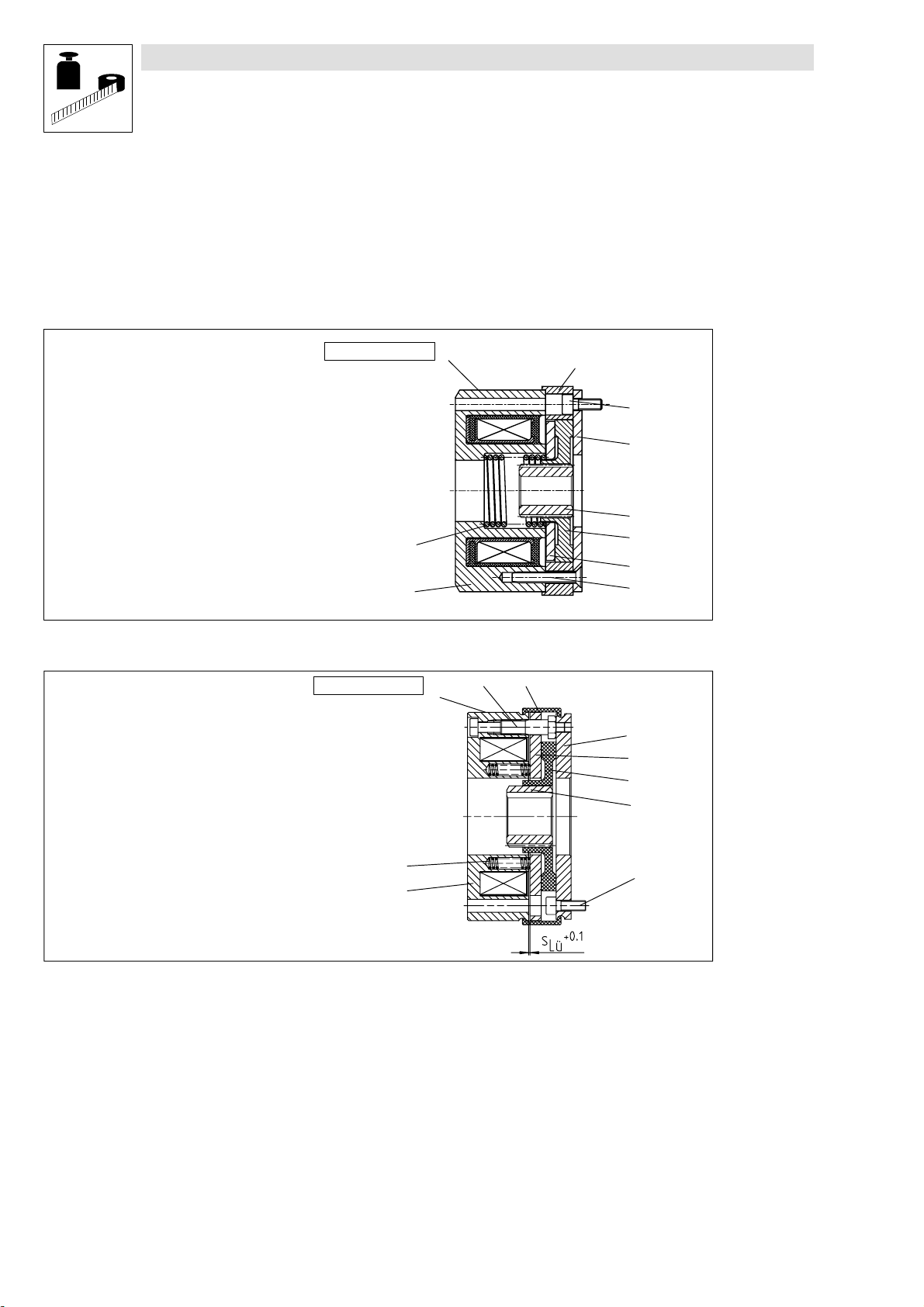
4.3.2 Installation of the brake BFK457-03...05 18........................................
4.3.3 Installation of the brake BFK457-06+08 18.........................................
4.3.4 Installation of cover seal for brake sizes 06+08 19...................................
4.4 Electrical connection 20..............................................................
5 Commissioning and operation 22.............................................
5.1 Operational test 22..................................................................
5.1.1 Release / voltage check 22.....................................................
5.2 During operation 22.................................................................

Contents
5
BA BFK457 GB 2.0
6 Maintenance / repair 23....................................................
6.1 Inspection intervals 23...............................................................
6.2 Inspections 23.....................................................................
6.2.1 Inspection of brake BFK457-03...05 23............................................
6.2.1.1 Releasing / voltage 23...............................................
6.2.2 Inspection of brake BFK457-06+08 23............................................
6.2.2.1 Rotor thickness 23.................................................
6.2.2.2 Air gap 24........................................................
6.2.2.3 Releasing / voltage 24...............................................
6.3 Maintenance 24....................................................................
6.3.1 Maintenance of brake BFK457-03...05 24..........................................
6.3.2 Maintenance of brake BFK457-06+08 25..........................................
6.3.2.1 Re-adjustment of airgap 25..........................................
6.4 Spare-parts list 26..................................................................
6.5 Orderof spare parts 27...............................................................
6.5.1 Spring-operated brake BFK457 27...............................................
7 Troubleshooting and fault elimination 28.......................................
Declaration of Conformity / Manufacturer’s Certification
Service addresses

Preface and general information
6
BA BFK457 GB 2.0
1 Preface and general information
1.1 About these Operating Instructions ...
l
These Operating Instructions are intended for safety-relevant operation on and with
electromagnetically released spring-operated brakes. They contain safety information which
must be observed.
l
All persons who work on and with electromagnetically relaeased spring-operated brakes must
have the Operating Instructions available and observe all relevant notes and instructions.
l
The Operating Instructions must always be in a complete and perfectly readable state.
1.1.1 Terminology used
Brake
In the following text, the term ”spring-operated brake” is used for ”electromagnetically released
spring-operated brake”.
Drive system
In the following text, the term ”drive system” is used for drive systems with spring-operated brakes
and other Lenze drive components.
1.2 Scope of supply
l
The drive systems are individually combined to the modular design. The scope of supply is
indicated in theaccompanying papers.
l
After reception of the delivery, check immediately whether the scope of supply matches with
the accompanying papers. Lenze does not accept any liability for deficiencies claimed
subsequently. Claim
– visible transport damage immediately to the forwarder.
– visible deficiencies/incompleteness immediately to your Lenze representative.

Preface and general information
7
BA BFK457 GB 2.0
1.3 Lenze drive systems
1.3.1 Labelling
l
Lenze drive systems and components are unambiguously designated by the indications on the
nameplate.
l
Manufacturer: Site:
Lenze GmbH & Co KG Bremsen Wülmser Weg 5
Postfach 10 13 52 D-31855 Aerzen
D-31763 Hameln
1.3.2 Application as directed
-Lenze drive systems
– are intended for the use in machines and systems.
– must only be used for the purposes ordered and acknowledged.
– must only be operated under theconditions stated in theOperating Instructions.
– must not be operated beyond the indicated power limits.
Any other use shall be deemed inappropriate!
1.3.3 Legal regulations
Liability
l
Theinformation,dataand notesintheseOperating Instructionsmet thestate of theart at the
time of printing. Claims referring to drive systems which have already been supplied cannot be
derived from the information, illustrations, and descriptions.
l
Lenze does not accept any liability for damage and operating interference caused by:
– must not be operated beyond the indicated power limits.
– unauthorized modifications to the controller.
– improper working on and with the controller.
– operating mistakes
– disregarding these Instructions.
Warranty
l
Warranty conditions: see Sales and Delivery Conditions of Lenze GmbH & Co KG Brakes.
l
Warrenty claims must be made immediately after detecting defects or faults.
l
The warranty is void all cases where liability claims cannot be made.

Safety information
8
BA BFK457 GB 2.0
2 Safety information
2.1 Persons responsible for the safety
Operator
l
An operator is any natural or legal person who uses the spring-operated brake on behalf of
whom the drive system is used.
l
Theoperatororhissafetyofficerareobliged
– to check whether all relevant regulations, notes, and laws are observed,
– that only qualified personnel work on and with the drive system,
– to ensure that the personnel have the Operating Instructions available for all corresponding
operations and
– to prohibit non-qualified personnel from working with and on the controller.
Qualified personnel
Qualified personnelarepersons who are- because of their education, experience, instructions,and
knowledge about corresponding standards and regulations, rules for the prevention of accidents,
and operating conditions- authorized bythepersonresponsibleforthesafetyof theplant toperform
the required actions and who are able to recognize and avoid potential hazards.
(see IEC 364, definition for qualified personnel).
2.2 General safety information
l
These safety notes do not claim to be complete. In case of questions and problems please
contact your Lenze representative.
l
At the time of supply the spring-operated brake is state-of-the-art and ensures basically safe
operation.
l
The spring-operated brake is hazardous to persons, the spring-operated brake itself and
other properties of the operator, if
– that only qualified personnel work on and with the spring operated brake.
– that the spring operated brake is not used improperly.
– Spring-operated brakes must be designed so that they comply with their function and do
not cause any hazards to personswhen correctly installed and in fault-free operation as
directed. This is also effective for the interaction with the entire system.
l
The spring-operated brake must only be operated in perfect state.
l
Retrofittings or changes of the spring-operated brake are generally prohibited. In any case,
Lenze must be contacted.
l
The friction linings must be carefully protected from grease or oil since even small amounts of
lubricants reduce the brake torque considerably.
l
With application conditions according to enclosure IP54, the brake torque will usually not be
reduced. Because of the great variety of applications, it is however necessary to check the
functionality of all mechanical components under the specific conditions.

Safety information
9
BA BFK457 GB 2.0
Possible applications of the spring-operated brake BFK457-PP:
l
No explosive or agressive atmostphere.
l
Humidity, no restriction.
l
Ambient temperature -20ECbis+40EC.
l
With high humidity and low temperatures
– Take measures to protect armature plate and rotor from freezing.
l
Electrical connections must be protected against contact.
2.3 Layout of the safety information
l
All safety information given in these Operating Instructions has the same layout:
Signalword!
Note
– The icon characterizes the type of danger.
– The signal word characterizes the severity of danger.
– The note describes the danger and suggests how to avoid the danger.
Warning of danger for persons
Icons used Signal words
Warning of hazar
d
o
s
e
l
e
c
t
r
i
c
a
l
Danger! Warns of impending danger.
P
o
s
s
i
b
l
e
c
o
n
s
e
q
e
n
c
e
s
i
f
d
i
s
r
e
g
a
r
d
e
d
:
d
o
u
s
e
l
e
c
t
r
i
c
a
l
voltage
P
o
s
s
i
b
l
e
c
o
n
s
e
q
u
e
n
c
e
s
i
f
d
i
s
r
e
g
a
r
d
e
d
:
Death or very severy injuries.
Warning! Warns of potential,very hazardous situations.
PDeath or very severe injuries.
P
o
s
s
i
b
l
e
c
o
n
s
e
q
e
n
c
e
s
i
f
d
i
s
r
e
g
a
r
d
e
d
:
Warning of a general
danger
P
o
ssible c
o
nsequences if dis
r
ega
r
ded:
d
a
n
g
e
r
Caution! Warns of potential,hazardous situations.
P
o
s
s
i
b
l
e
c
o
n
s
e
q
e
n
c
e
s
i
f
d
i
s
r
e
g
a
r
d
e
d
:
P
o
ss
i
b
l
ec
o
nsequences
i
f
d
i
s
r
ega
r
d
e
d
:
light or minor injuries.
Warning of material damage
Icons used Signal words
Stop! Warns of potential damage to material.
Possible consequences if disregarded:
Damage of the drive system/controller or its environment.
Other notes
Icons used Signal words
Note! Indicates a general, useful note.
If you observe it, handling of the controller/drive system is made easier.

Technical data
10
BA BFK457 GB 2.0
3 Technical data
3.1 Product description
1.1 Stator
1.2 Armature plate
1.4 Spring
1.6 Countersunk screwDIN7500
2.0 Rotor with friction lining
3.0 Hub
4.0 Cover seal
5.0 Flange
8.1 Socket head screws DIN912
K14.0607
4.0
8.1
5.0
3.0
2.0
1.2
1.1
1.4
Sticker - nameplate
1.6
FIG. 1 Spring-operated brake: BFK457-03...05
K14.0608
4.01.6
1.4
1.1 8.1
3.0
2.0
1.2
5.0
Sticker - nameplate1.1 Stator
1.2 Armature plate
1.4 Spring
1.6 Capscrews
2.0 Rotor with friction lining
3.0 Hub
4.0 Cover seal
5.0 Flange
8.1 Socket head screws DIN912
FIG. 2 Spring-operated brake: BFK457-06 + 08
3.1.1 General
The spring-operated brake type BFK457-PP is a single disc pulley with two friction surfaces. The
brake torque is generated by one (size 03...05) or several (size 06+08) pressure springs (1.4). The
brake is released electromagnetically.
Thespring-operated braketypeBFK457-PP is designed fortheconversionofmechanicalworkand
kinetic energy into heat energy. For operating speed see chapter 3.2 Rated data. Due to the static
brake torque, the brake can hold loads without speed difference. Emergency braking is possible at
high speed, see chapter 3.2, Rated Data. The more friction work, the higher the wear.

Technical data
11
BA BFK457 GB 2.0
3.1.2 Braking
When braking, the rotor (2.0), which is moveable on the hub (3.0), is pressed against the friction
surface by the central spring (size 03...05)or the inner and outer springs (1.4) (sizes 06+08) via the
armature plate (1.2). Theasbestos-freefriction linings ensure ahigh brake torque with low wear.The
brake torque is transmitted between hub (3.0)and rotor (2.0)via the splines.
3.1.3 Brake release
In braked state, there is an air gap sLübetween stator (1.1)and armature plate (1.2). To release the
brake, the stator coil (1.1) is excited with the DC voltage provided. The resulting magnetic force
attracts the armature plate (1.2) towards the stator (1.1) against the spring load. The rotor (2.0) is
released from the spring load and can rotate freely.
3.2 Rated data
Type Brake torque Rated
value at ∆n=100min-1
MK1)
[Nm]
Air gap sLü
[mm]
Tightening torque
of the fixing screws
[Nm]
Moment of inertial of
the rotor
[kg cm2]
Brake mass
[kg]
[
]
r
a
t
e
d
m
a
x
ra
t
e
d
max.
BFK457-03 0.5
1
3
0.019 0.4
BFK457-04 10.12 2) 0.4
1
.
3
0.031 0.5
BFK457-05 20.051 0.7
B
F
K
4
5
7
-
0
6
40.5 2.8
0
1
3
1
1
5
B
F
K
4
5
7
-
0
6
6
0
2
0.4
0
.
1
3
1
.
1
5
B
F
K
4
5
7
-
0
8
8
0
.
2
0.5
5
5
0
4
5
1
9
5
B
F
K
4
5
7
-
0
8
12 0.4
5
.
5
0
.
4
5
1
.
9
5
1) Minimum brake torque when all components are run in.
2) Minimum air gap, effective value results from the sum tolerances of the single components.
Type Rotor thickness
[mm]
Outer diameter
[mm]
Pitch circle
r
a
t
e
d
m
i
n
∅
[
m
m
]
w
e
i
g
h
t
ra
t
e
d
m
i
n.
∅
[
mm
]
we
i
g
h
t
BFK457-03 58 48 M3x8
BFK457-04 ----- ----- 67 58 M3x8
BFK457-05 77 66 M4x8
B
F
K
4
5
7
-
0
6
6
4
5
8
8
7
2
M
4
x
1
4
B
F
K
4
5
7
-
0
6
6
4
.
5
8
8
7
2
M
4
x
1
4
B
F
K
4
5
7
-
0
8
7
5
5
1
0
6
9
0
M
5
x
1
6
B
F
K
4
5
7
-
0
8
7
5
.
5
1
0
6
9
0
M
5
x
1
6

Technical data
12
BA BFK457 GB 2.0
Type Electrical power
P20
[W]
Voltage
U
[V]
Coil resistance
R20
[
W
]
Brake torque
rated value at
∆n=100min-1 MK
1)
[Nm]
Brake torque [Nm]
at ∆no
[min-1]
Maximum speed
∆nomax
[min-1]
Rated Max. Min. 1500 3000 max. hori-
zontal Braking during operation Emergency braking
BFK457-03 924
205 64
4669 66.7
5042 60.5
4295 0.5 0.45 0.42 0.35
BFK457-04 12.5 24
205 46
3362 48,6
3631 43,5
3093 10.89 0.82 0.68
BFK457-05 16 24
205 36
2626 37.9
2839 34
2415 21.76 1.62 1.34 12400
B
F
K
4
5
7
-
0
6
2
0
24 28.8 30.2 27.3 4
63.5
5.2 3.2
4.8 2.6
3.9 3000
B
F
K
4
5
7
-
0
6
2
0
205 2101 2270 1933 4
63.5
5.2 3.2
4.8 2.6
3.9
B
F
K
4
5
7
-
0
8
2
5
24 23 24.2 21.9 8
12 6.8
10.2 6.2
9.3 5.3
7.9
1
0
1
0
0
B
F
K
4
5
7
-
0
8
2
5
205 1681 1807 1554 8
12 6.8
10.2 6.2
9.3 5.3
7.9
1
0
1
0
0
1) Minimum brake torque when all components are run in.

Technical data
13
BA BFK457 GB 2.0
Type Brake torque
Rated value at
∆
n
=
1
0
0
m
i
n
-1
Friction work with
one switching
o
p
e
r
a
t
i
o
n
Transition
frequency
S
h
ü
Switching times [s]
at sLürated Spark suppressor
∆
n
=
1
0
0
m
i
n
1
MK1)
o
p
e
r
a
t
i
o
n
QE
S
hü DC engagement Separation Order number
[Nm] [J] [h-1]t11 t12 t1t2
BFK457-03 0.5 800 100 0.009 0.006 0.015 0.016
BFK457-04 11200 90 0.017 0.008 0.025 0.019
BFK457-05 21800 80 0.014 0.012 0.026 0.023
0
0
0
4
5
7
9
8
(
2
4
V
)
BFK457-06 4
63000 79 0.023
0.007 0.01
0.012 0.033
0.019 0.045
0.051
0
0
0
4
5
7
9
8
(
2
4
V
)
00045801 (205V)
BFK457-08 8
12 7500 50 0.036
0.020 0.014
0.021 0.050
0.041 0.045
0.088
1) Minimum brake torque when all components are run in.
3.3 Switching times
t1Engagement time
t2Separation time (up to M = 0.1 MK)
t11 Reaction delay during engagement
t12 Torque rise time of the brake torque
K 14.0583
FIG. 3 Switching times
The transitions from the state without brake torqueto the steady brake torque is not without delay.
The engagement times are valid for switching on the DC side with an induction voltage of approx.
5 to 10 times rated voltage. The diagramme shows the delay during engagement t11,therisetime
ofthebraketorquet12 and the engagement time t1=t11 +t12,as well as the disengagement timet2.
Disengagement time:
The disengagement time is not influenced by DC or AC switching operations. It can only be
shortened by special equipment for fast-response excitation or overexcitation.

Technical data
14
BA BFK457 GB 2.0
Engagement time
With switching on the AC side, the engagement times are prolonged extremely. They are approx.
10 times longer, connection see FIG. 11.
With the simplest connection of rectifier and brake directly parallel to the motor winding, the
engagement times are prolonged because the motor is switched off but still rotating so that the
brake is excited further. For connection see FIG. 10.
For DC switching, spark suppressors or 24 V and 205 V rated voltage are available. These
suppressors are to be connected in parallel to the contact. If, for safety reasons, for instance with
lifting systems, this type of connection is not allowed, the spark suppressor canalso beconnected
in parallel to the brake coil. For connection see FIG. 12.
3.4 Operating frequency / friction work
Q[J]
Sh[h-1]
10 102103104
10
102
103
104
08
06
05
03
04
QFrictionwork
ShSwitching frequency
FIG. 4 Friction work as function of the operating frequency, size 03...08
6
KSHUP
6
K
OQ Æ
4
4
(
É4
SHUP
4
(
ÆH
6K
6K
É
The permissible operating frequency Shpermdepends on the friction work Q (see diagramme). An
operating frequency of ShresultsinthepermissiblefrictionworkQ
perm.
With high speed and friction work, the wear increases strongly, because very high temperatures
occur at the friciton faces for a short time.

Technical data
15
BA BFK457 GB 2.0
3.5 Emission
Electromagnetic compatibility
For normal circuits with unsmoothed DC voltage via bridge connection, the spring-operated brake
type BFK457-PP complies with thge electromagnetic compatibility EN50081 Teil 1.
Pleasenote, that theentirecircuit onlycomplies withthe EMC Directive, ifit is configuredaccording
to one of the following possibilities:
Circuit: Rectifier Spark suppressor
p
a
r
a
l
l
e
l
t
o
A
C
v
o
l
t
a
g
e
Mains filters
complies with
standard
does not
comply with
standard
parallel to AC voltage
DC switching <=5
S
i
t
c
h
i
n
g
o
p
e
r
a
t
i
o
n
s
/
m
i
n
t
e
-
Switching operations / minute
- -
>=5
S
i
t
c
h
i
n
g
o
p
e
r
a
t
i
o
n
s
/
m
i
n
t
e
- -
Switching operations / minute
- -
AC switching <=5
S
i
t
c
h
i
n
g
o
p
e
r
a
t
i
o
n
s
/
m
i
n
t
e
-
Switching operations / minute
- -
>=5
S
i
t
c
h
i
n
g
o
p
e
r
a
t
i
o
n
s
/
m
i
n
t
e
-
Switching operations / minute
- -
Spark suppressor according to coil voltage on request.
Heat
Since the brake converts kinetic energy as well as mechanical and electrical work into heat energy,
the surface heat depends on theoperating conditions and theheat dissipation. Under unfavourable
conditions, the surface temperature can reach 130 EC.
Noises
The switching noises during engagement and disengagement depend on the air gap sLüand the
brake size.
Depending on the natural oscillation after installation, operating conditions and state of the friction
faces, the brake may squeak during braking.
Others
The abrasion of the friction parts produces dust.
With large loards, the frction face heats up so strongly, that odours may occur.

Installation
16
BA BFK457 GB 2.0
4 Installation
Warning!
Toothed hub or screws must not be lubricated with grease or oil.
4.1 Required tools
Type Torque wrench
Measuring range
[Nm]
Insert for hexagon socket
screws
Opening
[Inch]
Wrench
Opening
[mm]
BITS-holder
Opening
[Inch]
Insert for recessed head
screws
(Bits Phillips-recess)
Opening
[Inch]
Cap screws
BFK457-03
2
5
x
1
/
4
”
s
q
a
r
e
5
0
m
m
l
o
n
g
-
-
-
-
-
BFK457-04 0.3 - 4
2
,
5
x
1
/
4
”
squa
r
e
5
0
mm
l
ong ----- ----- -----
BFK457-05 3x1/4” square 55mm long
BFK457-06
1
-
1
2
3x1/4” square 55mm long 8
1
/
4
”
s
q
a
r
e
d
r
i
v
e
1/4” - drive 1PH70mm
long
BFK457-08
1
-
1
2
4x1/4” square 55mm long 9
1
/
4
”
squa
r
e
d
r
i
v
e1/4” - drive 2PH70mm
long
Feeler gauge Caliper gauge Multimeter

Installation
17
BA BFK457 GB 2.0
4.2 Assembly
4.2.1 Preparation
1. Unpack spring-operated brake.
2. Check for completeness
3. Check nameplate data, especially rated voltage.
4.3 Installation
4.3.1 Installation of the hub onto the shaft
3.0 Hub
3.1 Circlip
10.0 Endshield
3.0
3.1
10.0
K14.0611
FIG. 5 Installation of thehub onto theshaft
1. Press hub (3.0)onto the shaft.
2. Secure hub against axial displacement (e.g. using a circlip - 3.1).

Installation
18
BA BFK457 GB 2.0
4.3.2 Installation of the brake BFK457-03...05
K14.0609
K140611/1
1.0 Spring-operated brake
3.0 Hub
10.0 Endshield
1.0
3.0
10.0
FIG. 6 Installation of thebrake
1. Hub (3.0)installation, chapter 4.3.1.
2. Push spring-operated brake (1.0)onto the hub (3.0)FIG. 6
3. Bolt the spring-operated brake (1.0)to the endshield using the fixing screws (8.1)FIG. 6
4. Tighten the screws (8.1)evenly (for torques see the table Rated data, chapter 3.2 and FIG. 6
4.3.3 Installation of the brake BFK457-06+08
1. Hub (3.0)installation, chapter 4.3.1.
2. Push spring-operated brake (1.0)onto the hub (3.0). Secure hub against axial displacement
(e.g. using a circlip - 3.1).
K14.0616
10.0
3.0
1.0
1.0 Spring-operatedbrake
3.0 Hub
10.0 Endshield
FIG. 7
3. Bolt the spring-operated brake (1.0)to the endshield using the fixing screws (8.1).

Installation
19
BA BFK457 GB 2.0
K14.0616/1
1.0 Spring-operatedbrake
10.0 Endshield
12.0 Torque wrench 12.0
10.0
1.0
FIG. 8
4. Tighten the screws (8.1)evenly (for torques see the table Rated data, chapter 3.2 and FIG. 8.
4.3.4 Installation of cover seal for brake sizes 06+08
K14.0614
1.1 Stator
1.2 Armature plate
2.0 Rotor
4.0 Cover seal
5.0 Flange
8.1 Socket head screw
10.0 Endshield
1.1 4.0 5.0
1.2
2.0
10.0
K14.0608/1
4.0
8.1
1.1 10.0
FIG. 9 Installation - cover seal
1. Pull the cable through the seal (4.0).
2. Push the seal (4.0) over the stator (1.1).
3. Press the lips of theseal (4.0)into the grooveof stator (1.1)and
flange (5.0).

Installation
20
BA BFK457 GB 2.0
4.4 Electrical connection
Warning!
The brake must only be electrically connected when no voltage is applied.
¥Bridge rectifier
¥
K14.0525
FIG. 10 Switching parallel to motor, extremely delayed engagement
¥Bridge rectifier
¥
K14.0525/2
FIG. 11 DC switching
delayed engagement
Table of contents