Leroy Merlin 4226 User manual
4226
Please Read The User Manual Carefully!

2
1 Safety instructions 4
1.1 Operating instructions 4
1.2 Instructions employed 4
1.3 Children, persons with special needs 5
1.4 Intended use 5
1.5 Risk of re 6
1.6 Power supply 6
1.7 Defective equipment 6
2 Unpacking and assembly 7
2.1 Unpacking 7
2.2 Assembly and electrical connection 7
3 Operation 13
3.1 Performance level select fan 13
3.2 Automatic trailing system 13
4 Maintenance 16
4.1 General maintenance instructions 15
4.2 Cleaning the extraction hood 16
4.3. Clean the metal grease lter 17
4.4 Removing and inserting the metal grease lter 18
4.5 Maintenance intervals 19
4.6 Replacing the light source 19
4 Malfunctions 20
5 Malfunctions/Causes/Solutions 21
3
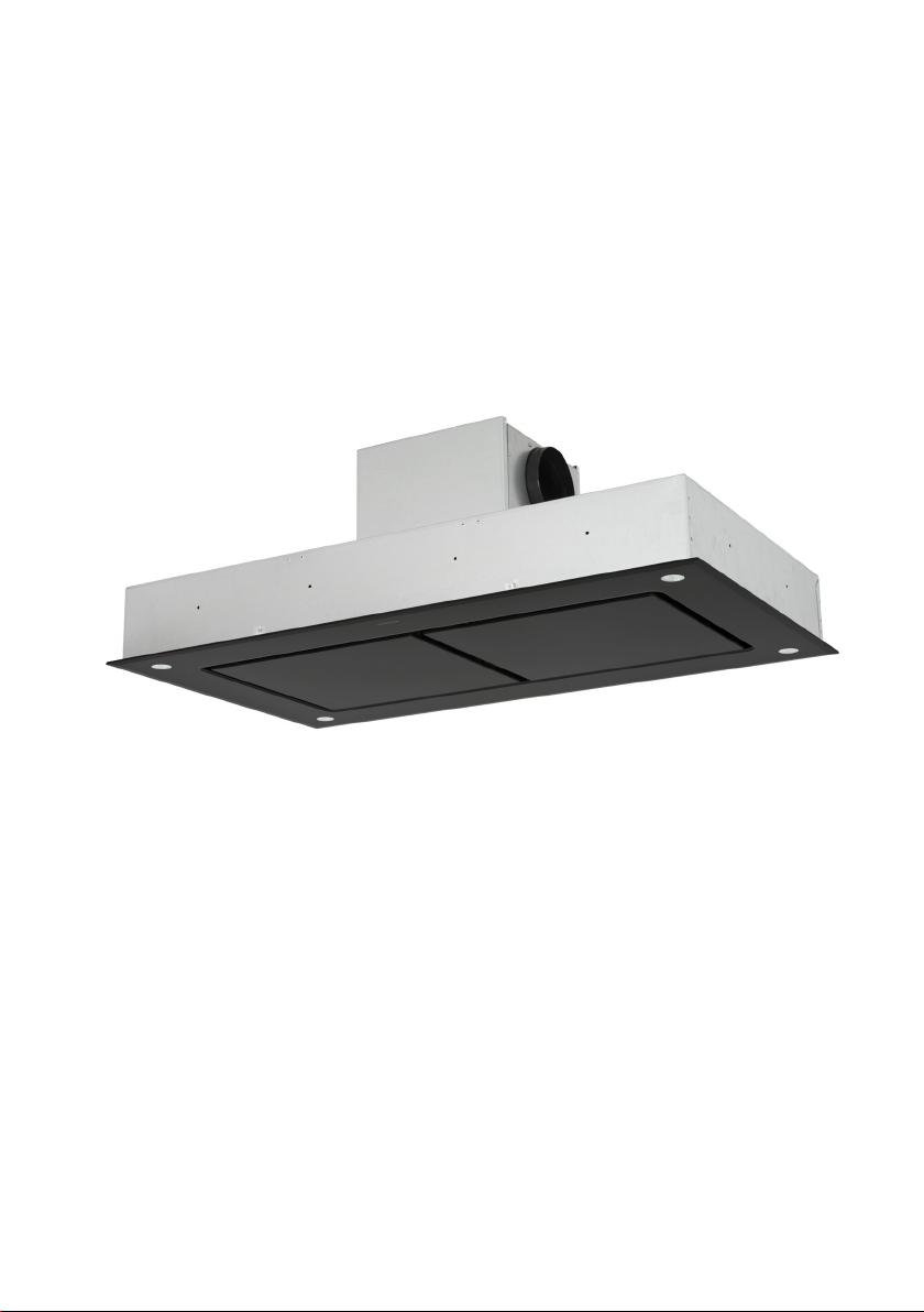
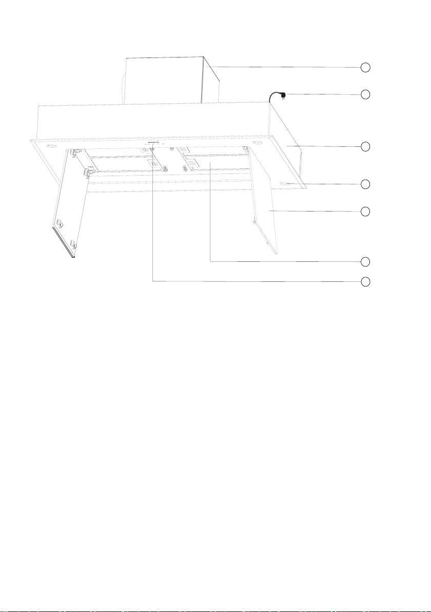
Overview of extraction hood
Figure 1: Overview 1 Motor box
2 Power plug
3 Cover housing
4 Lighting
5 Side suction-plate is removable.
6 Metal grease lter
7 Light diodes of hood remote control
1
2
3
4
5
6
7
4
Read through these operating instructions
completely before working with the extraction
hood.
Store these operating instructions carefully.
When forwarding the equipment to a third
party, deliver the operating instructions.
It is imperative to respect instructions to avoid
injuries to persons and damage to equipment.
No liability is assumed of the manufacturer
for damages arising from non-compliance of
these operating instructions.
Important instructions for your safety are spe-
cically identied. It is imperative to respect
instructions to avoid accidents and damage to
equipment.
1 Safety instructions
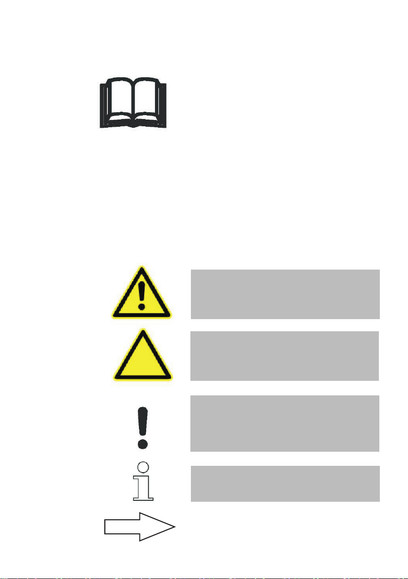
WARNING!
Warns of risks to health and shows potential
risks of injury.
CAUTION!
Indicates the dangers of the device or other
objects
CAUTION!
Indicates a potential danger, which can lead to
material damage if it is not avoided.
INSTRUCTION!
Shows tips and information.
Refers to another chapter, a section or inst-
ruction.
1.1 Operating instructions
1.2 Instructions employed
5
1 Safety instructions
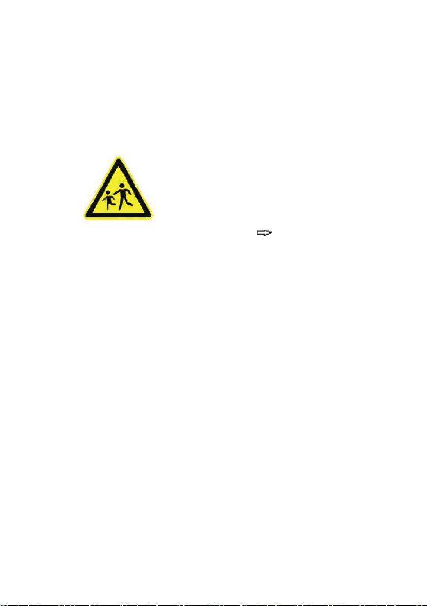
Persons (including children), who are not ca-
pable of using the equipment safely (persons
with special needs) due to mental, physical or
motor capacities, may not use the equipment
without the supervision or only with the inst-
ructions of a competent person.
Do not leave the equipment unattended. Use
is only with greatest caution when children
or persons with special needs, who cannot
assess the risks correctly, are in the vicinity.
Packaging material:
- not used for games. There are
Risk of suffocation.
- Appropriate packaging material
dispose of ( spare parts and disposal).
The extraction hood is only intended for
cleaning of cooking vapours rising from
the cooking site and for private use in the
household.
- Only use the equipment in the household.
- The equipment is not intended for commer-
cial
use.
- Extraction hood only for the use over
electrical or gas cooking sites.
- Any other use is not considered as
conditional and is prohibited.
In particular, refrain from:
- Operating the extraction hood without the
metal grease lter. Missing the metal grease
lter leads
to massive grease accumulation in the extrac-
tion hood and the exhaust ducts.
- Flames under the extraction hood. It
may result in ignition of the grease accumu-
lation
.
- The operation of the cooking pot (all types of
heating: gas, electricic, etc.) without
cookware.
1.3 Children, persons with spe-
cial needs
1.4 Intended use
6
1 Safety instructions
- Open ames can lead to ignition
in the extraction hood.
- Cleaning the extraction hood with
unapproved means or
equipment, e. g. with a steam cleaner
( Maintenance).
- Repairs by an
unauthorised person ( Customer ser-
vice).
WARNING!
Risk of combustion Combustion may result
during faulty operation of the extraction
hood.
-Maintenance and cleaning instructions are
correctly complied with ( 4.6 Maintenance
intervals).
Basically refrain from:
- cook, roast and grill with open
ames due to the risk of re.
1.5 Risk of re
In the case unauthorised personnel inter-
vene, warranty and guarantee claims expire (
Warranty)
1.7 Defective equipment
WARNING!
Electric shock The extraction hood is opera-
ted with electricity. If the assembly, handling
and operation are wrong, it can result in
severe or fatal injury. Observe safety instruc-
tions.
1.6 Power supply
CAUTION!
Do not install or operate a defective extrac-
tion hood. Repairs are performed by specia-
lised personnel authorised by the manufactu-
rer ( Customer service).
7
2 Unpacking and assembly
The packaging material is recyclable. Save
the raw material and reduce the volume of
waste. Resupply package in the material cyc-
le. Your technician will revoke the packaging.
( 6.2 Disposal).
Observe the safety instructions for the as-
sembly and electrical connection ( Safety
instructions). Read the assembly instructions
completely before assembling.
It is imperative to respect instructions to
avoid injuries to persons and damage to
equipment.
No liability is assumed of the manufacturer
for damages arising from non-compliance of
these assembly instructions.
2.1 Unpacking
2.2 Assembly and electrical con-
nection
2.3.1 Testing the extraction hood
parts
These consist of:
- Extraction hood with motor box
Accessories:
- 10 screws and washers
8
2.3.2 General information on
assembly
WARNING!
Risk to life due to damage of supply lines. Du-
ring boring, supply lines (electricity, gas and/
or water lines) can be damaged. Before boring
be informed of the route of the supply lines (e.
g. with a search tool for metal and liv wires).
2 Unpacking and assembly
The extraction hood is attached ush-
mounted at the surface in the centre over the
cooktop.
9
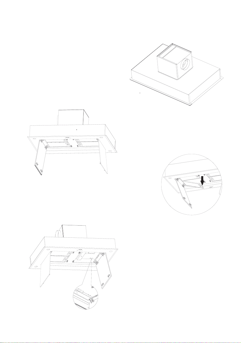
2.3.3 Assembly diagrams
Figure M3
Figure
M2a
Figure M1
Figure
M2b
2 Unpacking and assembly

10
2 Unpacking and assembly
2.3.4 Preparations for hood as-
sembly
- They require a ceiling section with a stable
wooden frame made of square timber or the
like.
The section dimensions are:
Vega interior: 1000 mm
(VGID 104) 958 mm x 656 mm
Vega interior: 1200 mm
(VGID 124) 1158 mm x 656 mm
- They can connect the exhaust air in all direc-
tions to the motor box (g.1). By turning the
motor box, you bring the air vents with a Ø
of 150 mm in the desired direction to the wall
sleeve or other part.
- Before installing the hood, transfer and join
the exhaust duct with a diameter of 150 mm
up to the wall sleeve or other part
1. Ceiling section
2. Exhaust air duct connection
direction
3. Installation of the exhaust air
duct from the hood to the wall slee-
ve or the like
Table of contents
Popular Ventilation Hood manuals by other brands

Gorenje
Gorenje S3 IHGC963S4X manual

KOBE
KOBE ISX2136SQB-1 Installation instructions and operation manual

U.S. Products
U.S. Products ADVANTAGE-100H Information & operating instructions

Kuppersberg
Kuppersberg DUDL 4 LX Technical Passport

Framtid
Framtid HW280 manual

Thermador
Thermador HGEW 36 FS installation manual


