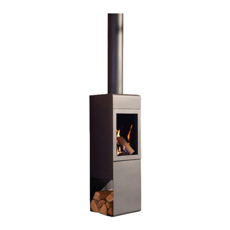
Les foyers DON-BAR Fireplaces 9000 User manual

Installation, Operation
and Maintenance Manual
LES FOYERS
FIREPLACES
DON-BAR
FREE-STANDING
FIREPLACES
Les foyers DON-BAR Fireplaces, inc.
Shop and Showroom: 741, St-Vallier Ouest, Quebec (Quebec) G1N 1E2
Phone: (418) 686-9114 - Fax: (418) 686-9117
9120
9800
9200
9000
98009800
9123
REV. 2013-02

Page 2
IMPORTANT
The installation shall meet the requirements of CAN/CSA B-365 - Installation
code for solid-fuel-burning appliances and equipment.
Don-Bar fireplaces are not designed to be connected to air-ventilated
factory-built chimneys (chimneys without insulation).
The ceiling support (standard or cathedral) is universal and used with all the
fireplaces mentioned in this manual. The installation can be done in two
practical steps:
1) The chimney and its ceiling support can be installed during the
the construction phase; the fireplace is not required for this step.
2) Then, you can wait until the work is complete to select the fireplace
model and proceed to final installation. This protects the fireplace
from being damaged and there is no hassle of protecting the fireplace
during construction.
If you are not sure
maximum clearances from combustible materials (Pages 6 and 17 to 21)
For simplicity, the Model 9000 is the only type illustrated in the drawings.
Installation of other models is similar.
which fireplace you'll be choosing, it's best to allow
A gas burner (propane or natural gas) with ceramic logs can also be installed.
The burner and its accessories must be certified by the concerned authorities
and meet the local codes and regulations where the fireplace will be installed.
CAUTION: The painted finish of the cathedral and regular ceiling
supports must remain visible to the eye. Because of dangers of fire,
these elements should not be covered with finishing materials other
than those supplied and approved by Don-Bar.
REV. 2013-02
KEEP THIS MANUAL IN A
SAFE PLACE FOR FUTURE USE
THE 9000 SERIES FIREPLACES MEET THE REQUIREMENTS OF:
ULC S627 - Space Heater for use with Solid Fuel, 2000
UL 1482 - Standard for Safety Solid-Fuel Type Room Heater, 2006
EPA - Certified EPA Exempt

LES FOYERS
FIREPLACES
DON-BAR
Installation, Operation,
and Maintenance Manual
The Manual is divided into 5 parts:
PART 1: Installation ...........................................
PART 2: Security, Operation and Maintenance...
PART 3: Parts List .............................................
Page 5
Page 23
Page 27
Page 28
Page 29
PART 4: Chimney Fires.....................................
PART 5: Warranty ............................................
Page 3
REV. 2013-02
This document in its entirety is the intellectual property of Les Foyers Don-Bar inc.
Any unauthorized use will expose its author or authors to legal and financial penalties.
Copyright © 2011 - Les Foyers Don-Bar inc.

1. Important Notice 9. Outside air intake installation
9.1 Important notice
2. Listed chimneys 9.2 Floor boring
9.3 Duct type and diameter
3. Before beginning the 9.4 Exterior wall vapor barrier
installation 9.5 Outside hood
3.1 Choosing the best location 9.6 Connecting the air intake duct to the fireplace
3.2 Chimney pedestal
3.3 Chimney minimum height
3.5 Outside air intake 10. Floor protection installation
3.5 Minimum clearances from combustible 10.1 Protection of combustible floors
materials 10.2 Removing the existing resilient flooring
10.3 Protection under the pedestal
4. Installation
4.1 Choosing the ceiling support 11. Fireplace pedestal installation
11.1 Pedestal installation
5. Regular ceiling support 11.2 Completing the pedestal installation
installation
5.1 Wood frame 12. Glass firescreen
5.2 Ceiling support fastening 12.1 Standard firescreen 9000 and 9120
5.3 Chimney 12.2 Pivot firescreen 9200, 9800, 9123, 9086
5.4 Radiation shield (Optional for 9000 and 9120)
6. Cathedral ceiling support 13. Installation of the optional hood
installation (standard and decorative panels (9000,9200,9800)
ventilated) 13.1 Installation of the decorative hood panels
6.1 Cathedral ceiling support wood 13.2 Sub-panel fastening
frame 13.3 Decorative panels installation
6.2 Ceiling support fastening
6.3 Outside air intake (ventilated support) 14. BBQ grill installation
6.4 Chimney start 14.1 BBQ supports installation
7. Factory-built chimney 15. Gas burner (optional)
installation 15.1 Gas burner installation
7.1 UL listed parts 15.2
7.2 Manufacturer's instructions 15.3
7.3 Obstructions 15.4
7.4 Maximum authorized offsets 15.5
7.5 Chimney weight
7.6 Radiation shield/fire stop
7.7 Minimum chimney height above the roof
7.8 Flashing water tightness
7.9 Roof braces
7.10 Chimney top
8. Fireplace hood installation
8.1 Hood fastening
8.2 Joint gasket
Regulations and certification
Neutral pressure required
CO detector
Connection of the outside air intake
PART 1: INSTALLATION Contents
Page 4
REV. 2013-02

PART 1: INSTALLATION
WARNING: Any modification, change, or
substitution of any fireplace component and/or
not following the installation, operation, and
maintenance instructions will void the
warranty and can put your security at risk.
1.1 Before installation begins, carefully read the
manual and contact your local building
department to determine whether a building
permit is required to install a fireplace.
1.2 The installation must follow the instructions
in this manual and local building codes. If there is
a conflict, you must follow the more restrictive
measures.
1.3 For your security, enlist the services of a
professional fireplace fitter for the installation.
1.4 Before lighting your first fire, read the
instructions in Part 2 regarding Security,
Operation and Maintenance.
1.5 Your fireplace produces heat and provides
great ambiance but it should not be used as the
main source of heating.
2.1 Listed factory-built chimneys: Your Don-
Bar fireplace is designed to be installed with any
prefabricated chimney bearing the ULC-S610 or
UL-103HT label. The chimney inside diameter
shall be 10" (250 mm). If the height of the
insulated chimney above the ceiling support
exceeds 18' (5500 mm), a chimney of 8" I.D. (200
mm) is acceptable.
1. IMPORTANT NOTICE
2. Listed chimneys
DRAWING 1
Attic
Insulation
Attic insulation
Shield/Fire stop
Radiation/Dust
Shield
Fireplace
DON-BAR 9000
Don-Bar
Ceiling
Support
Floor
Protection
Glass
firescreen
air wash
system
Round Top
Storm Collar
Flashing
Roof Support
Factory-built
insulated Chimney
10 inches I.D.
Typical Installation
Page 5
REV. 2013-02

3. Before beginning the installation ceiling support requires 20-1/4” x 20-1/4” (515
mm) - see next page. Do not connect this
fireplace to a chimney that is connected to
3.1 Choosing the best location: Before another heating device.
beginning the installation, make sure the spot you
have in mind for the fireplace and the chimney 3.3 Chimney minimum height: 15 feet (4600
meet the following requirements: mm). This length is measured from the floor
where the fireplace is installed to the top of the
chimney.
3.4 Outside air intake: Outside air needs to
circulate into the fireplace. The outside air intake
duct needs to pass under the floor that supports
the fireplace. Plan an appropriate path for this 6"
to 8" (150 to 200 mm) outside diameter duct,
including its insulated jacket.
3.2 Chimney: Position the chimney to avoid, as
much as possible, offsets, elbows and the cutting-
out of structural elements. Allow at least 2" (50
mm) for air space between the chimney and any
combustible material including electrical cables,
and plastic plumbing pipes. Never fill this air
space with insulation. For example, if the
chimney has an outside diameter of 12" (305
mm), by adding the required 2" (50 mm) air
space, a 16" (406 mm) free continuous path is
required to install the chimney. Note: The
standard ceiling support requires a free vertical
space of 17” x 17” (430 mm) and the cathedral
Fireplace
DON-BAR 9000
Floor
Protection
12" min. (305 mm)
18" min. (460 mm)
See pages 17 to 21
DRAWING 2
Fireplace clearances from
combustible walls
(See also pages 17 to 21)
Wall
Floor
Protection
Fireplace Table
Wood Basket
Furniture
Wall
Fireplace clearances from walls
and combustible furniture
(See also pages 17 to 21)
DRAWING 3
Page 6
12" min.
(305 mm)
12" min.
(305 mm)
See pages 18 to 23
See pages 18 to 23)
REV. 2013-02
18" min.
(460 mm) Beam

Page 7
Attic
insulation
Attic
insulation
Attic insulation
shield / fire stop
Radiation
dust shield
DON-BAR
9000 Fireplace
(all models)
DON-BAR
9000 Fireplace
(all models)
Don-Bar
ceiling support
(universal)
Don-Bar
cathedral ceiling
support
Floor
protection Floor
protection
Chimney cap
Chimney cap
Storm collar Storm collar
Flashing Flashing
Roof support Roof support
Factory built
insulated chimney
10" I.D.
Factory built
insulated chimney
10" I.D.
Vertical shaft of 17" x 17" required
for the installation of the standard
ceiling support
Vertical shaft of 20-1/4” x 20-1/4"
required for the installation of the
cathedral ceiling support
Glass
firescreen
with air
wash
system
Glass
firescreen
with air
wash
system
VERTICAL SHAFT 17" x 17"
VERY MPORTANT : A continuous vertical shaft of 20-1/4" x 20-1/4" (515 mm
x 515 mm) minimum must be planned for the installation of the chimney and
its ceiling support. This technical shaft must be free of joists, beams,
trusses, pipes, electrical wires, etc. before the installation of the chimney.
See article 7.4 for the maximum permitted offsets.
VERY IMPORTANT : A continuous vertical shaft of 17" x 17" (430 mm x 430
mm) minimum must be planned for the installation of the chimney and its
ceiling support. This technical shaft must be free of joists, beams, trusses,
pipes, electrical wires, etc. before the installation of the chimney. See
article 7.4 for the maximum permitted offsets.
Cathedral ceiling
support
Hood
Frame
20-1/4" x 20-1/4”
Longbolt
holes
18" c/c
20" x20"
Standard
ceiling
support
(universal)
Frame
17" x 17"
Hood
VERTICAL SHAFT 20-1/4" x 20-1/4”
Wood frame for the
regular ceiling support
Wood frame for the
cathedral ceiling support
REV. 2013-02
IMPORTANT: The frame must
be made of solid wood, 1-1/2"
(38 mm) minimum thickness.
(2x6, 2X8 or 2X10 x 1.5in.)
Frame: 2x6, 2x8
or 2x10 x 1.5 in.
minimum thickness

Wood frame for the
regular ceiling
support
DRAWING 4
Don-Bar
regular
ceiling support
Fireplace hood to
be bolted to the
ceiling support
17"
(430 mm)
17" (430 mm)
Long bolt holes
at 18" c/c
(460mm)
ceiling support
20" x20"
(508mm x 508mm)
3.5 Minimum clearances from combustible
materials: Make sure the wood basket (see
drawings 2 and 3) is at least 12" (305 mm) from
any combustible material, including furniture,
drapes and other flammable objects. Note that
Type X fire-resistant gypsum board (Firecode) is
considered combustible for fireplaces
installations and as such requires the minimum
12" (305 mm) clearance.
3.6 Exterior doors and windows: As much as
possible, avoid installing the fireplace too close to
an outside door or window because air turbulence
and drafts disrupt the chimney draft.
4.1 Choosing the ceiling support: If you have a
horizontal ceiling, use the regular Don-Bar
ceiling support. For a sloped ceiling, use the
Don-Bar cathedral ceiling support.
5.1 Wood frame: Build a ceiling wood frame of
17" x 17" I.D. (432 mm x 432 mm) to anchor the
ceiling support. The ceiling support long bolts
are spaced at 18" c/c (457 mm). Level the frame
so that the suspended hood will be plumb. Note
that these wood frame dimensions are required
to fix the ceiling support. Elsewhere, the
chimney may require smaller clearances. See
the requirements of the chimney's
manufacturer for more details.
5.2 Ceiling support fastening: Secure the
regular Don-Bar ceiling support to the wood
frame with 4 long bolts at least 3" (75 mm) long
by 3/8" (10 mm) diameter.
5.3 Chimney: Start the chimney installation by
slipping the first chimney section into the ceiling
support. Be sure the chimney fits well into the
ceiling support before proceeding with other
chimney sections.
4. Installation
5. Regular ceiling support
installation
DRAWING 5
Chimney start on the regular
ceiling support
Factory-Built
Chimney
10" I.D.
(250 mm)
Fireplace Hood to
be bolted to the
Ceiling Support
Don-Bar
Regular Ceiling
Support
Fixing Bolt
Radiation
Shield
Long Bolt
17" (430 mm) required for long bolts
2" (50 mm)
Minimum
Mandatory Air
Space
2" (50 mm)
Minimum
Mandatory Air
Space
Page 8
REV. 2013-02

20-1/4" (515 mm)
Cathedral
Ceiling
Support
Insulation
Rigid
Insulation
Long Bolt
Fireplace hood
to be bolted to
the support
The cathedral
ceiling support
must extend below
the finished ceiling
as indicated in the
Table of DRAWING 6
Bolt
Factory-Built
Chimney
10" i. D.
(250 mm)
3" (75 mm)
Trim Collar
DRAWING 7
20-1/4"
(515 mm)
20-1/4"
(515mm)
Wood frame for the cathedral
ceiling support
Don-Bar
Cathedral
Ceiling
Support
Visible part
of the ceiling
support
Hidden part
of the ceiling
support
Fireplace Hood
to be bolted to the
Cathedral Ceiling
Support
Build a 20-1/4" x 20-1/4" (515 x 515 mm)
frame to anchor the
Don-Bar Cathedral Ceiling
Support
This side of the cathedral
ceiling support must extend below
the finished ceiling as
specified here
DRAWING 6
5.4 Radiation heat shield: Next, slip a radiation fix the ceiling support. Elsewhere, the
heat shield down the wood frame to protect the chimney may require smaller clearances. See
wood against radiant heat from the chimney. the requirements of the chimney's
manufacturer for more details.
6.1 Cathedral ceiling support wood frame:
Build a ceiling wood frame of 20-1/4" x 20-1/4"
I.D. (515 x 515 mm) to anchor the Don-Bar
cathedral ceiling support. Level the frame so that
the suspended hood will be plumb. Note that
these wood frame dimensions are required to
6. Cathedral ceiling support installa-
tion (standard and ventilated) Standard cathedral ceiling support
Ventilated cathedral ceiling
support
2" (50 mm)
Mandatory
Air Space
Page 9
Damper key
Outside
air supply
Outside air
intake with damper
6" (150 mm)
REV. 2013-02
PITCH PITCH PITCH
MUST EXTEND MUST EXTEND MUST EXTEND
Minimum extension of the cathedral ceiling support
below the finished ceiling according to the ceiling slope.
1/12
2/12
3/12
4/12
5/12
6/12
7/12
8/12
9/12
10/12
11/12
12/12
14/12
16/12
18/12
20/12
22/12
24/12
2" (50 mm)
2.5" (65 mm)
3" (74 mm)
2" (50 mm)
2" (50 mm)
2" (50 mm)
3.5" (90 mm)
4
4.5
5
5.5" (140 mm)
6" (150 mm)
" (100 mm)
" (115 mm)
" (125 mm)
7" (175 mm)
8
9
10
11" (280 mm)
12" (300 mm)
" (200 mm)
" (230 mm)
" (250 mm)

6.2 Ceiling support fastening : Secure the
ceiling support to the wood frame with 8 long
bolts at least 1,5" (40 mm) long by 5/16" (8 mm)
diameter (2 long bolts per side).
6.3 Outside air intake (Ventilated cathedral
support only) : The diameter of the outside air
intake is 6" (150 mm). If necessary, it is possible
to connect an insulated flexible duct to supply
outside air to the fireplace.
6.4 Chimney start: Begin the installation of the
chimney by slipping the first chimney section into
the cathedral ceiling support. Be sure the chimney
fits well into the ceiling support before
proceeding with other chimney sections. Never
let the attic insulation be in contact with the
chimney. Always allow a 2" (50 mm) minimum
air space between the chimney and adjacent
materials.
7.1 Listed parts: Use only ULC or UL listed
parts supplied by the chimney manufacturer when
installing the chimney.
allowed offsets would include: four 30-degree
7.2 Manufacturer's instructions: The elbows (4x30=120) or two 45-degree elbows plus
installation must follow the instructions in this two 15-degree elbows (2x45+2x15=120).
manual and the chimney manufacturer's
instructions. If there is a conflict, you must follow 7.5 Chimney weight: The weight of the
the more restrictive measures. chimney may rest in part on the ceiling support.
However, offset supports must be installed above
7.3 Obstructions: If a joist obstructs the path and as close as possible to each offset (elbow) in
of the chimney and the mandatory 2" (50 mm) the chimney. Also install extra chimney supports
minimum clearance, the joist should be moved or at the intervals required by the chimney
cut. In either cases, the structure must be manufacturer's instructions.
reinforded to maintain its solidity. Seek
engineering help if you are not absolutely certain 7.6 Radiation shield/firestop: Install a radiation
of what you are doing. If electrical cables or shield/firestop every time the chimney passes
plastic plumbing pipes are in the way, a through a combustible wall or ceiling.
specialized contractor should remove them.
7.7 Minimum chimney height above the roof:
7.4 Maximum allowed offsets: Don't install Extend the chimney at least 3 feet (1 m) above
more than 4 elbows in the chimney. Offsets the roof or 2 feet (610 mm) above any
cannot be more than 45 degrees from the vertical construction element within 10 feet (3 m) of the
axis. The sum of all offsets (elbows) must never chimney.
exceed 120 degrees. For example, maximum
7. Factory-built chimney installation
10 feet (3 m) Radius
2 feet min.
(610 mm) min.
3feet(1 m) min.
Warning: Lateral roof braces need to
be installed when the unsupported
chimney height above the roof
is more than 6 feet (2 m).
Chimney minimum height above
the roof
DRAWING 8
Page 10
REV. 2013-02
7.8 Flashing water tightness: Install a metal
roof flashing with a storm collar where the
chimney pass meets the roof. Seal the joint 9.1 IMPORTANT: The outside air intake is an
between the chimney and the storm collar and the option to bring in fresh air under the wood basket
joint between the roofing and the flashing. and save energy. It is not mandatory. In the case
of concrete floors, radiant floors, old buildings it
7.9 Roof braces: Any chimney that extends can be difficult to install. In this case, a similar air
more than 6 feet (2 m) above the roof needs to be supply can be acheived by opening a window or
laterally strengthened with a pair of telescopic by rebalancing the air exchanger. If you install an
roof braces. air intake, make sure the duct is not trapped or
crushed by mistake. The air intake duct should be
7.10 Chimney top: Install a chimney round top extended to outside the building. It is forbidden to
at the end of the chimney. leave an air intake end in a garage, attic or any
room mechanically ventilated with a negative
pressure.
9.2 Floor cutting: Cut a 7" to 8" hole through
8.1 Fastening: Bolt the fireplace hood to the
the floor under the fireplace pedestal for the
ceiling support with the 4 supplied bolts.
passage of the outside air intake duct. Center the
hole as much as possible trying not to cut a joist.
8.2 Joint gasket: Before fully tightening the
bolts, insert the supplied compressible gasket
9.3 Duct type and diameter: Use a 6" (150
between the ceiling support and the fireplace
mm) I.D. flexible duct covered by a fiber glass
hood in order to make the joint airtight.
insulating jacket with an integrated vapor barrier.
9.4 Sealing the wall vapor barrier: Following
the piercing of the exterior wall for the passage of
the air intake duct, seal the flexible duct vapor
barrier jacket against the exterior wall vapor
barrier. This will prevent ice built up inside the
wall. Use an adhesive aluminum tape.
9.5 Outside hood: Complete the installation by
connecting the duct to the hood assembly. Fix the
hood on the wall and seal the joint with silicone.
The hood should be fitted with a screen.
9.6 Connecting the air intake duct to the
fireplace pedestal: Inside, secure the duct
against the sleeve located under the fireplace
pedestal. Use metal screws in addition to
aluminum tape or duct collars to fasten the duct.
10.1 Floor protection: When a fireplace is
installed directly on a combustible floor, an
incombustible protection must placed underneath
and extended around the fireplace to protect the
8. Fireplace hood installation
9. Outside air intake installation
10. Floor protection installation
DRAWING 9
Insulated Flexible Duct Hood Assembly
Outside air intake installation
Page 11
REV. 2013-02
The installation
of 1 or 2 CO/CO2
detectors is
always
recommended

floor against the accidental fall of embers. In
order to achieve this goal, all joints of the floor
protection must be perfectly adjusted or filled
with grout. The floor protection may consist of:
a) Slabs or tiles of stone (marble, granite,
slate, etc.) or ceramic at least 3/8" (10 mm)
thickness, secured in place;
b) Bricks of concrete or terra-cotta, secured
in place;
c) For a temporary floor protection, a sheet
metal of at least 0.015" (0,38 mm) thickness
or an incombustible composite cement board
of at least 3/8" (10 mm) thickness may be
used.
10.3 Protection under the pedestal: The
floor protection must extend at least 6" (150 mm)
under the fireplace pedestal.
10.2 Removing the existing resilient flooring: 11.1 Pedestal installation: Center the pedestal
Before beginning the installation of the floor under the suspended hood. Level it using the 4
protection, remove any existing resilient flooring leveling bolts built in the base.
(linoleum, carpet, etc.) in order to reach the wood
or concrete sub-flooring. The fireplace must not
rest on resilient flooring.
11. Fireplace pedestal installation
Extend the floor
protection at least 6"
(150 mm) under
the pedestal. The
opening for the
passage of
the outside air
intake duct
must be at
least 7" diameter
(180 mm)
See pages18 to23
See pages18to 23
DRAWING 10
Floor protection
extension under
the pedestal
Ash drawer
9000 Pedestal
(the 9120 pedestal
is pyramidal
without an
ash drawer)
Table
Wood basket Grate
DRAWING 11
Pedestal assembly
Page 12
Bolts for
adjusting the
table height
REV. 2013-02

Page 13
11.2 Completing the pedestal installation: glass with a silicon drop and slip it in place on the
Complete the installation by putting the table, the glass pane. Install each bracket at about 3" (75
wood basket and the grate on the pedestal, as mm) from the glass edge. Quickly clean any
illustrated. These parts are simply placed with no excess silicone, then let dry.
particular fastening. Finish the installation by
slipping the ash drawer into its slot on the 12.1.3 Installation of the three stationary glass
pedestal. panes: Once the silicone has dried, install, as
shown, the three stationary glass panes. Join
them at each upper corner with the special steel
comers supplied with the fireplace. Don't glue
the steel corners in place with silicone because,
from time to time, they need to be removed in
order to clean the glass.
12.1.4 Removable glass pane: Install a handle
at mid-level on each side of the fourth removable
glass pane. In order to protect the glass from
accidentally breaking, place the little metallic
strip on the glass before tightening the small
fastening screws.
12.2 Hinged firescreen: Fireplaces 9200, 9800,
9123 (Optional for 9000 and 9120)
- Drawing 13:
12.2.1 Installation of the tubular steel
structure: The hinged glass firescreens of the
9200, 9800, and 9123 fireplaces (optional for
9000 and 9120) are held in place with a steel
structure consisting of 4 tubular posts bolted in
place using the supplied bolts. The opening
doors have a latch while the other glass panes are
either simply inserted in the provided channel
(9200) or assembled as opening doors but without
a latch in the case of the 9000, 9120, 9800 and
12.1 Standard firescreen: Fireplaces 9000 and
9123 (Drawing 13).
9120 - Drawing 12
12.2.2 Spacing washers: The steel posts are
12.1.1 Assembling the tempered glass
supplied with a number of small spacing washers.
firescreen: The glass firescreen consists of 4
These washers are used to lift the posts to a
tempered glass panes of the same dimensions,
height equivalent to the thickness of the ceramic
supplied with stabilizing steel brackets. Three of
or stone finish of the fireplace table. The weight
the glass panes are stationary, the fourth is
of the posts shall never rest directly on ceramic or
removable and equipped with two handles to
stone, but on the steel spacing washers. For the
allow easy loading of the wood.
appearance, drill holes in the ceramic or stone
finish to conceal the washers.
12.1.2 Stabilizing bracket installation: Each
glass pane must be fitted with two stabilizing
brackets (8 stabilizing brackets are supplied with
the fireplace). Glue the stabilizing bracket on the
12. Glass firescreen
DRAWING 12
Standard firescreen assembly
(9000, 9120) Steel
Corner
Handle
Stationary
Tempered
Glass
Panes
Stabilizing
Foot
Removable
Tempered
Glass Pane
REV. 2013-02
DANGER of BREAKING GLASS : NEVER stuck the glass
firescreen under the hood as it will explode when the hood
expands under the heat. The glass firescreen must be put
outside the hood, never under.

Page 14
13. Installation of the optional hood
decorative panels (9000, 9200, 9800)
13.2 Sub-panel fixation: Drill 1/8" (3 mm)
diameter holes in the fireplace hood where sub-
panel fixations are located (if not already done at
shop). Adjust the sub-panels to let a regular 1"
13.1 Installation of the decorative hood (25 mm) free space between each panel. Fix the
panels: The installation of the decorative panels sub-panels in place with 3/8" (10 mm) long
must be done in two steps. First, the sub-panels metal screws.
must be fixed directly on the fireplace hood with
metal screws. Next, the decorative panels are 13.3 Decorative panels installation: Set the
simply laid in place over the sub-panels without decorative panels in place handling them with
any fastening. care to prevent damages. Decorative panels are
simply laid down in place over the sub-panels.
No fastening is required.
DRAWING 13
Installation of the optional structural tubular frame for
the pivot doors (9000, 9120)
Lower fixing bolt
inserted from
under the table
(Note: Bolt not
required for
retro-fit installations)
Sliding frame
filling the joint
between the
doors and the table
(for retro-fit installations
only)
Upper fixing bolt Fastener keeping
the doors closed
Retaining square
to be laid down on
the hood interior fold
for a sandwich
hold
Handle with
tongue latch
Fireplace table
pivot
support
Opening panes
Glass door assembly
pivot
Pivot
Spacing washers
piled up to the
height of the
decorative finish
laid on the table
REV. 2013-02

Page 15
14. BBQ grill installation
15. Gas burner (optional)
14.1 BBQ brackets installation: Fix one of the
three BBQ grill brackets on each side of the
fireplace wood basket with the supplied wing nuts
and bolts. Next, install the support rod and the
BBQ grill at the desired level.
15.5 Connection of the outside air intake:The
outside air intake located below the burner support
plate must be connected to a flexible insulated duct
of at least 6” diameter. The air intake’s flexible duct
must be extended to reach the outdoors and a fresh
air supply. It should not end in an attic space,
another room, crawl space or any other confined
space; that space being vented or not.
15.1 Gas Burner (Propane or Natural Gas):
The installation requires a special table equipped
with a support plate and integrated air intake, as
well as a pedestal with an access door (Drawing
15). The installation must follow the instructions
of the burner manufacturer, local codes and the
present section of this manual where it is most
restrictive.
15.2 Regulations and certification: The
installation must be done in conformity with the
standards regulating gas installations in the locality
where the fireplace will be installed. The burner and
its accessories must have the approved
certification of the authorities of the country in
question
.
15.3 Neutral pressure required: Special care
must be taken regarding pressures and air
movements inside the area where the fireplace will
be installed. There must be no negative pressure
(vacuum) in the fireplace’s environment. The
outside air intake supplied with the fireplace only
serves to ensure it’s correct operation in a neutral
pressured environment. Certain conditions that are
out of our control ( Air exchangers, windows,
dryers, cooker hoods, air movements between
floors, etc.) can produce negative pressures in the
fireplace’s environment. In that case, all required
measures must be taken to rebalance pressure and
obtain neutral or, even better, a slightly positive
pressure.
15.4 CO detector: A carbon monoxide detector
must be installed in the room where the fireplace
will be installed. Check batteries on a regular basis. DRAWING 15
Gas burner installation
(optional)
Burner controls
hidden in the
pedestal
Special gas
pedestal with
an access door
Table
Burner
support plate
Replace the rigid gas pipe
supplied with the burner
with an approved flexible
gas pipe
Flexible gas
Gas burner
pipe
Adjustable
levelling bolts
Outside air intake
with damper to be
connected to a 4" (100 mm)
dia. insulated flexible
duct that reaches
the outdoors
REV. 2013-02

Page 16
REV. 2013-02

MINIMUM REQUIRED CLEARANCES
Page 17
12" min.
(305 mm)
12" min.
(305 mm)
58” (1475 mm)
Wall
12"
(300 mm)
32" (810 mm)
20"
(510 mm)
40" (1020 mm)
22" (560 mm) 19-1/2" (495 mm)
20" (510 mm)
Made-to-measure table
also available
standard 39" (991 mm)
or made-to-measure
20" (510 mm)
4" (100 mm)
9000
17” (432 mm)
16" (406 mm) to
Adjustable from
19" (483 mm)
58" (1475 mm)
22" (560 mm)
22" (560 mm)
Floor Protection
58" x 58"
(1475 x 1475 mm)
Fireplace Table
Wood Basket
REV. 2013-02
Floor Protection:
This fireplace is approved with
a wood basket placed at 12 "
(305 mm) of a combustible wall.
In this case the floor protection
shall be extended to the wall.
Floor
Protection
12" min. (305 mm)
18" min. (460 mm)
Wall 18" min.
(460 mm) Beam
Fireplace
DON-BAR 9000

14"
(356 mm)
32,25" (820 mm)
35" (900 mm)
48" (1220 mm)
22" (560 mm)
20" (510 mm)
standard 45"
(1143 mm) or
made-to-measure
Page 18
18-1/4" (464 mm)
12" min.
(305 mm)
12" min.
(305 mm)
9120
58" (1475 mm)
58" (1475 mm)
22" (560 mm)
22" (560 mm)
MINIMUM REQUIRED CLEARANCES
Wall
Fireplace Table
Wood Basket
Floor Protection
58" x 58"
(1475 x 1475 mm)
17” (432 mm)
16" (406 mm) to
Adjustable from
18" (460 mm)
REV. 2013-02
19-1/2" (495 mm)
Floor Protection:
This fireplace is approved with
a wood basket placed at 12 "
(305 mm) of a combustible wall.
In this case the floor protection
shall be extended to the wall.
Floor
Protection
12" min. (305 mm)
18" min. (460 mm)
Wall 18" min.
(460 mm) Beam
Fireplace
DON-BAR 9120

98009800
Page 19
9800
Floor protection
54" x 54"
(1372 x 1372 mm)
12" min.
(305 mm)
12" min.
(305 mm)
18" (457 mm)
18" (457 mm)
54" (1372 mm)
54" (1372 mm)
MINIMUM REQUIRED CLEARANCES
Wall
Fireplace Table
Wood Basket
standard 40,5"
(1030 mm) or
made-to-measure
17” (432 mm)
16" (406 mm) to
Adjustable from
19" (483 mm)
13"
34-5/8"
(880 mm)
26"
(660 mm)
20" (510 mm)
20" (510 mm)
4" (100 mm)
(330 mm)
43-1/2"
(1105 mm)
REV. 2013-02
18,5" (470 mm)
Floor Protection:
This fireplace is approved with
a wood basket placed at 12 "
(305 mm) of a combustible wall.
In this case the floor protection
shall be extended to the wall.
Fireplace
DON-BAR 9800
Floor
Protection
12" min. (305 mm)
18" min. (460 mm)
Wall 18" min.
(460 mm) Beam

Floor protection
40" x 53"
(1016 x 1345 mm)
12" min.
(305 mm)
12" min.
(305 mm)
53” (1345 mm)
12"
(300 mm)
8" (203 mm)
32" (813 mm)
36" (914 mm)
standard 40"
(1016 mm) or
made-to-measure
20" (510 mm)
4" (100 mm)
24"
(610 mm)
22" (600 mm)
28,5" (724 mm)
19" (724 mm)
24" (610 mm)
18"
(457 mm)
Front Side
9200
17” (432 mm)
16" (406 mm) to
Adjustable from
19" (483 mm)
22,5" (572 mm)
40" (1016 mm)
17" (432 mm)
20" (510 mm) 20" (510 mm)
MINIMUM REQUIRED CLEARANCES
Wall
Fireplace Table
Wood
Basket
Page 20
REV. 2013-02
19-1/2" (495 mm)
Fireplace
DON-BAR 9200
Floor
Protection
12" min. (305 mm)
18" min. (460 mm)
Wall 18" min.
(460 mm) Beam
Fireplace
DON-BAR 9200
Floor Protection:
This fireplace is approved with
a wood basket placed at 12 "
(305 mm) of a combustible wall.
In this case the floor protection
shall be extended to the wall.
This manual suits for next models
4
Table of contents
Other Les foyers DON-BAR Fireplaces Indoor Fireplace manuals
Popular Indoor Fireplace manuals by other brands

Dimplex
Dimplex CAS400LNH-INT Assembly guide

Vermont Castings
Vermont Castings Montpelier Medium Insert owner's manual

Petromax
Petromax fb1 user manual

ATRAFLAME
ATRAFLAME FA23V60L-8 manual

Town & Country Fireplaces
Town & Country Fireplaces TCW120 operating instructions

Superior Fireplaces
Superior Fireplaces VRE3036ZMN Installation and operation instructions