LeSuire Avalanche User manual

Owner`s Manual
August ´23
300W All-Tube Bass Amplifier
ENG
DE

2
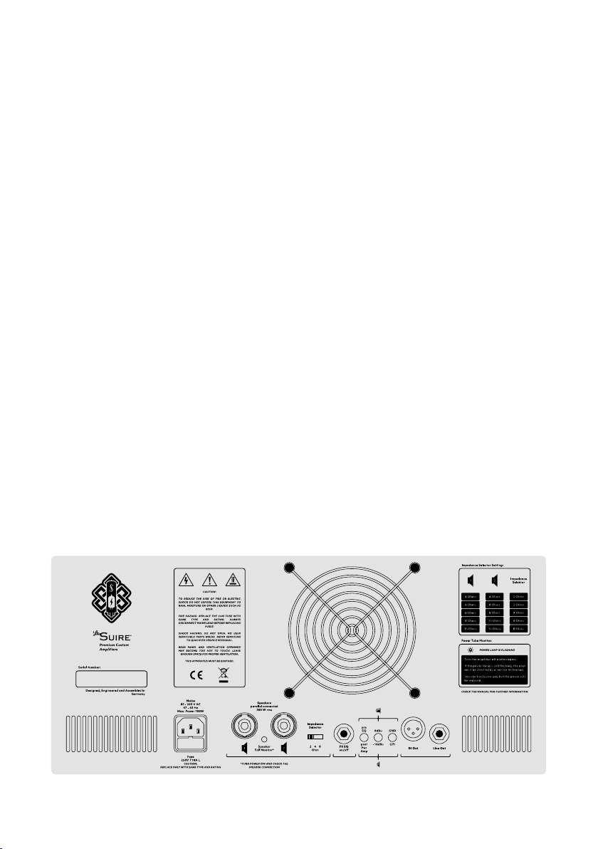
General safety instructions!
Read before connecting!
• Read this manual carefully, including the safety instructions.
• Keep this instructions.
• Follow all instructions and safety notes on the device and in this manual.
• Do not operate the device near water, bathtubs, sinks, etc., or in damp areas.
• Do not set up the device in a damp or wet environment.
• Do not place any objects containing liquids, e.g. vases, bottles, glasses, etc., on
the device.
• Clean the device only with a dry cloth.
• Do not block any ventilation openings on the device to prevent overheating.
Adequate ventilation must be ensured while operating the device.
• Do not install near heat sources such as radiators, heat registers, stoves other
devices that produce heat.
• Do not bring open ames, e.g. candles, near the device.
• Allow a cold device to warm up to ambient temperature before comissioning,
else the temperature dierence can cause condensate to form inside the device
and damage it.
• The device can generate a very high volume level. This can damage your hearing
permanently. Only use the device with adequate hearing protection.
• Before connecting to the mains, check if the local mains supply voltage is within
the requirements for the operating voltage of this device. If you are not sure
about the mains supply voltage, please consult the local mains power supplier.
• This device must be grounded. The grounding must not be interrupted. Only use
adequately dimensioned three-core cables with safety plugs and test marks as
power supply cables. Check the cable for damage before use.
• Never use a damaged power supply cable.
• Disconnect the device from the mains during a thunderstorm and when not in
use for longer periods of time.

3
This symbol warns you of dangerous, non-insulated voltage inside the
housing.
This symbol warns you of externally accessible, dangerous voltage.
Only use professionally assembled cables at connections marked with
this symbol.
This symbol warns you of hot surfaces. To prevent burns you must not
touch.
This symbol draws your attention to operating and maintenance
instructions that must be observed.
• Replace the fuse only with a fuse of the same type and rating, observing the
information on the device and in these instructions. Never use a short-circuited
fuse and never bridge the fuse holder.
• Do not insert any objects through the housing slots. This may touch components
that carry life-threatening voltages.
• Do not remove any covers or parts of the housing and do not open the device.
• Maintenance work and repairs may only be carried out by qualied service
personal. Life-threatening voltages occur inside the device.
• The manufacturer guarantees the function, safety and reliability of the device
only if the device is used in accordance with these instructions.

4
Content
1.1. ForewordForeword
2.2. Connections and controlsConnections and controls
3.3. Monitoring functionsMonitoring functions
4.4. Technical dataTechnical data
5.5. ServiceService
Additional notes on handling tube ampliers!
Observe these instructions to increase the service life of the tubes and to
avoid damage to the device!
• Tubes are mechanically sensitive components. Avoid strong vibrations. Be careful
when setting up and transporting the device.
• Operate the device only with a connected speaker or load resistor, otherwise the
protection circuit will become active and the device will switch to standby mode.
Do notfallbelow the set minimum impedance(refertothe corresponding section
in this manual), as this will lead to increased tube wear. Only use suciently
dimensioned and fault-free speaker cables for connecting the speakers.
• When starting up the amplier, observe the warm-up phase to bring the tubes
to operating temperature. After switching o the amplier, observe the cooling
phase of the tubes. Allow the unit to cool down for a few minutes after switching
o the power switch. When heated up, tubes are particularly susceptible to
shocks.

5
1. Foreword
With the purchase of the Avalanche bass amplier you have chosenWith the purchase of the Avalanche bass amplier you have chosen
an absolute premium product. By combining modern and traditionalan absolute premium product. By combining modern and traditional
circuit technology, in conjunction with the best possible components,circuit technology, in conjunction with the best possible components,
it has been possible to create a new generation of tube ampliers.it has been possible to create a new generation of tube ampliers.
300 watts of tube power deliver an indescribably harmonious and300 watts of tube power deliver an indescribably harmonious and
powerful sound.powerful sound.
Features:Features:
•• Very light weight of 10,6 kgVery light weight of 10,6 kg
•• Very low noise designVery low noise design
•• Active tube EQ with two parametric mid bandsActive tube EQ with two parametric mid bands
•• Auto Bias circuit for each power amp tube seperatlyAuto Bias circuit for each power amp tube seperatly
•• Switching power supply with constant regulated voltages andSwitching power supply with constant regulated voltages and
current monitoringcurrent monitoring
•• Power factor correction for lower load on the power gridPower factor correction for lower load on the power grid
•• Soft start of the tube heaterSoft start of the tube heater
•• Mains voltage range from 85 – 240 Vac without switching forMains voltage range from 85 – 240 Vac without switching for
worldwise useworldwise use
•• Loudspeaker monitoring circuit to protect the amplier fromLoudspeaker monitoring circuit to protect the amplier from
missing or defective loudspeakersmissing or defective loudspeakers
•• Silent cooling system with fan monitoring for signicantly longerSilent cooling system with fan monitoring for signicantly longer
tube lifetube life
•• Tube-saving standby circuit without disconnection of the anodeTube-saving standby circuit without disconnection of the anode
voltagevoltage
We wish you many great gigs with the LeSuire Avalanche!We wish you many great gigs with the LeSuire Avalanche!

6
2. Connections and controls
FrontFront
IInputnput
Due to the extremely low-noise input amlier, the input is equallyDue to the extremely low-noise input amlier, the input is equally
suitable for both passive and active instruments. For passive basses,suitable for both passive and active instruments. For passive basses,
you should also pay attention to a low cable capacitance. Fromyou should also pay attention to a low cable capacitance. From
approx. 350 pF a loss in the treble becomes perceptible. Unshieldedapprox. 350 pF a loss in the treble becomes perceptible. Unshielded
cables (e.g. speaker cables) cause extreme background noise andcables (e.g. speaker cables) cause extreme background noise and
cannot be used.cannot be used.
GainGain
The gain control adjusts the gain of the preamp. To minimize noise,The gain control adjusts the gain of the preamp. To minimize noise,
the gain should be set as high as possible. For a clean sound, nd thethe gain should be set as high as possible. For a clean sound, nd the
point where distortion becomes audible and lower the gain a bit. Forpoint where distortion becomes audible and lower the gain a bit. For
distorted sounds, the gain can be increased as desired.distorted sounds, the gain can be increased as desired.
BassBass
This can be used to raise or lower the level at 70 Hz by +/- 16 dB.This can be used to raise or lower the level at 70 Hz by +/- 16 dB.
Lo-Mid Frequency / Lo-MidLo-Mid Frequency / Lo-Mid
This allows the level to be raised or lowered by +/- 16 dB betweenThis allows the level to be raised or lowered by +/- 16 dB between
180 Hz and 800 Hz, depending on the Lo-Mid Frequency control.180 Hz and 800 Hz, depending on the Lo-Mid Frequency control.

7
Hi-Mid Frequency / Hi-MidHi-Mid Frequency / Hi-Mid
This allows the level to be raised or lowered by +/- 16 dB betweenThis allows the level to be raised or lowered by +/- 16 dB between
600 Hz and 3 kHz, depending on the Hi-Mid Frequency control.600 Hz and 3 kHz, depending on the Hi-Mid Frequency control.
TrebleTreble
This can be used to raise or lower the level at 5.6 kHz by +/- 16 dB.This can be used to raise or lower the level at 5.6 kHz by +/- 16 dB.
EQ on/oEQ on/o
The EQ on/o switch turns the equalizer on and o via true bypass. TheThe EQ on/o switch turns the equalizer on and o via true bypass. The
LED signals that the EQ is on.LED signals that the EQ is on.
In many cases, the tone control on the instrument is already sucientIn many cases, the tone control on the instrument is already sucient
to nd the desired sound. The characteristics of the instrument areto nd the desired sound. The characteristics of the instrument are
brought out best this way. The EQ can then be used to provide anbrought out best this way. The EQ can then be used to provide an
additional sound. With the optional foot switch, this function can alsoadditional sound. With the optional foot switch, this function can also
be controlled remotely.be controlled remotely.
EQ VolEQ Vol
With the EQ Vol control the volume after the tone controls can beWith the EQ Vol control the volume after the tone controls can be
set. This is helpful to adjust the volume ratios between activated andset. This is helpful to adjust the volume ratios between activated and
deactivated EQ or to selectively call up a dierent volume, e.g. for adeactivated EQ or to selectively call up a dierent volume, e.g. for a
solo.solo.
MasterMaster
The Master control is used to adjust the overall volume. Before startingThe Master control is used to adjust the overall volume. Before starting
to play, the knob should be set to zero if possible to avoid unexpectedlyto play, the knob should be set to zero if possible to avoid unexpectedly
high volumes.high volumes.

8
Stand ByStand By
The standby switch mutes all outputs of the amplier and reduces theThe standby switch mutes all outputs of the amplier and reduces the
quiescent current in the power tubes.quiescent current in the power tubes.
Theswitch should be used,forexample,whilechangingtheinstrument.Theswitchshould be used,forexample,whilechangingtheinstrument.
During pauses, you can reduce tube wear in the standby position.During pauses, you can reduce tube wear in the standby position.
The often discussed eect of‚cathode poisoning‘ does not occur withThe often discussed eect of‚cathode poisoning‘ does not occur with
the Avalanche. Thus, even prolonged operation in standby mode isthe Avalanche. Thus, even prolonged operation in standby mode is
not harmful to the tubes. Nevertheless, one should keep in mind thatnot harmful to the tubes. Nevertheless, one should keep in mind that
energy is consumed to heat the tubes.energy is consumed to heat the tubes.
Thanks to the soft start feature, there is no need to pay attention to theThanks to the soft start feature, there is no need to pay attention to the
sequence of switches when turning on the amp.sequence of switches when turning on the amp.
PowerPower
In the „o“ position, the device is disconnected from the mains andIn the „o“ position, the device is disconnected from the mains and
does not consume any energy.does not consume any energy.
When switching o, it makes sense to toggle the standby switch rst.When switching o, it makes sense to toggle the standby switch rst.
A slight clicking noise can be prevented with this.A slight clicking noise can be prevented with this.
BackBack

9
MainsMains
Connection for the supplied power cable. Only cables with a protectiveConnection for the supplied power cable. Only cables with a protective
earth conductor and a test symbol may be used. Damaged cables mustearth conductor and a test symbol may be used. Damaged cables must
not be used under any circumstances. The Avalanche is designed for anot be used under any circumstances. The Avalanche is designed for a
voltage of 100 - 240 Vac / 50-60 Hz and can therefore be operated onvoltage of 100 - 240 Vac / 50-60 Hz and can therefore be operated on
any mains power supply without further precautions.any mains power supply without further precautions.
FuseFuse
The fuse may only be replaced by a fuse of the same type and valueThe fuse may only be replaced by a fuse of the same type and value
(250 V, T10A L). A replacement fuse is integrated in the fuse holder.(250 V, T10A L). A replacement fuse is integrated in the fuse holder.
If the fuse blows again after replacement, there is damage and theIf the fuse blows again after replacement, there is damage and the
manufacturer should be contacted.manufacturer should be contacted.
SpeakersSpeakers
The speakers are connected to the speakon/jack combination sockets.The speakers are connected to the speakon/jack combination sockets.
If possible, use cables with speakon plugs. The use of jack plugs is alsoIf possible, use cables with speakon plugs. The use of jack plugs is also
possible. A minimum cross-section of 1.5 sq. mm. or 16 AWG for thepossible. A minimum cross-section of 1.5 sq. mm. or 16 AWG for the
speaker cable is recommended. Instrument cables are not suitable!speaker cable is recommended. Instrument cables are not suitable!
Both jacks are equal and allow the connection of many speakerBoth jacks are equal and allow the connection of many speaker
combinations. Set the impedance switch accordingly (see table below).combinations. Set the impedance switch accordingly (see table below).
The total power rating of the speakers should be at least 300Wrms.The total power rating of the speakers should be at least 300Wrms.
Otherwise the destruction of the loudspeakers is possible.Otherwise the destruction of the loudspeakers is possible.
Impedance SelectorImpedance Selector
This switch is used to set the total impedance of the connectedThis switch is used to set the total impedance of the connected
speakers according to the following table. Please also note the powerspeakers according to the following table. Please also note the power
specications. When using a single speaker, the value is set accordingspecications. When using a single speaker, the value is set according
to the speaker specications.to the speaker specications.

10
For other combinations the value can beFor other combinations the value can be
calculated with the following formula:calculated with the following formula:
Set the next possible smaller value.Set the next possible smaller value.
Footswitch EQ on/oFootswitch EQ on/o
Used to connect the optional foot switch. The foot switch has theUsed to connect the optional foot switch. The foot switch has the
same function as the switch on the front of the device. Third-partysame function as the switch on the front of the device. Third-party
products can only be operated with this connection after modication.products can only be operated with this connection after modication.
Otherwise, the switching relay may be damaged. Contact theOtherwise, the switching relay may be damaged. Contact the
manufacturer for further information.manufacturer for further information.
DI OutDI Out
The XLR connection is used for direct pickup of the amp for FOH orThe XLR connection is used for direct pickup of the amp for FOH or
recording situations. Only shielded XLR audio cables should be used.recording situations. Only shielded XLR audio cables should be used.
Cable lengths up to 150 m are possible without any problems.Cable lengths up to 150 m are possible without any problems.
Speaker 1 Speaker 2 Switch position
4 Ohm / 150 Wrms 4 Ohm / 150 Wrms 2 Ohm
4 Ohm / 200 Wrms 8 Ohm / 100 Wrms 2 Ohm
8 Ohm / 150 Wrms 8 Ohm / 150 Wrms 4 Ohm
8 Ohm / 200 Wrms 16 Ohm / 100 Wrms 4 Ohm
16 Ohm / 150 Wrms 16 Ohm / 150 Wrms 8 Ohm
Fig. Loudspeaker impedance combinations

11
Pre EQ / post Pwr AmpPre EQ / post Pwr Amp
The position of this switch aects the DI output signal.The position of this switch aects the DI output signal.
In the ‚pre EQ‘ position, the signal is tapped after the input amplier.In the ‚pre EQ‘ position, the signal is tapped after the input amplier.
Only the gain control is eective. EQ and master volume have no eect.Only the gain control is eective. EQ and master volume have no eect.
In position ‚post Pwr Amp‘ the signal is tapped after the power ampIn position ‚post Pwr Amp‘ the signal is tapped after the power amp
section. All controls have an inuence on the DI signal.section. All controls have an inuence on the DI signal.
0 dBu / -10 dBu0 dBu / -10 dBu
This switch can be used to reduce the output level of the DI and LineThis switch can be used to reduce the output level of the DI and Line
outputs by 10 dB. For optimal signal quality, the‚0 dB‘ position (switchoutputs by 10 dB. For optimal signal quality, the‚0 dB‘ position (switch
is not pressed) should normally be used. For some analog inputs theis not pressed) should normally be used. For some analog inputs the
level may be to high, which can lead to overload. Then the switchlevel may be to high, which can lead to overload. Then the switch
should be pressed.should be pressed.
GND / LiftGND / Lift
Depending on the stage or studio situation, it can happen that a so-Depending on the stage or studio situation, it can happen that a so-
called hum or ground loop is created via the protective earth conductorcalled hum or ground loop is created via the protective earth conductor
and the audio cable to the mixing console, which leads to audibleand the audio cable to the mixing console, which leads to audible
noise in the amp or the downstream electronics. Pressing the buttonnoise in the amp or the downstream electronics. Pressing the button
will break this loop. Under no circumstances should you interrupt orwill break this loop. Under no circumstances should you interrupt or
tape o the protective conductor for this purpose. Normally the switchtape o the protective conductor for this purpose. Normally the switch
should not be pressed.should not be pressed.
Line OutLine Out
This makes the DI signal available for unbalanced applications.This makes the DI signal available for unbalanced applications.

12
3. Monitoring functions
Power LEDPower LED
After switching on the device with the power switch, the power LEDAfter switching on the device with the power switch, the power LED
slowly starts to light up. The current brightness indicates the progressslowly starts to light up. The current brightness indicates the progress
of the soft start. A short ashing at the beginning of the soft start isof the soft start. A short ashing at the beginning of the soft start is
used to check the fan monitoring.used to check the fan monitoring.
Fan monitoringFan monitoring
A continuous ashing of the power LED indicates that the fan is notA continuous ashing of the power LED indicates that the fan is not
working. In this case, check whether the ventilation grille is heavilyworking. In this case, check whether the ventilation grille is heavily
soiled or the fan is blocked by an object. If no cause can be detectedsoiled or the fan is blocked by an object. If no cause can be detected
from the outside, this indicates that the fan is defective. The device canfrom the outside, this indicates that the fan is defective.The device can
still be operated, but this will increase the wear of the tubes. The fanstill be operated, but this will increase the wear of the tubes. The fan
should be replaced immediatly. Contact the manufacturer for this.should be replaced immediatly. Contact the manufacturer for this.
Speaker Fail MonitorSpeaker Fail Monitor
A glow of the LED on the back of the device signals that the impedanceA glow of the LED on the back of the device signals that the impedance
of the connected speakers is to high and the amplier switches toof the connected speakers is to high and the amplier switches to
standby mode. This saves the amplier from getting damaged.standby mode. This saves the amplier from getting damaged.
Possible causes:Possible causes:
•• No speakers connectedNo speakers connected
•• Speakon connector not properly plugged and lockedSpeakon connector not properly plugged and locked
•• Speaker cable defectiveSpeaker cable defective
•• Loudspeakers burnt outLoudspeakers burnt out
To put the amplier back into operation after the fault has beenTo put the amplier back into operation after the fault has been
eliminated, it must be switched o briey with the power switch.eliminated, it must be switched o briey with the power switch.

13
4. Technical data
Tube assembly
3x ECC83 / 12AX7 / 7025
2x ECC82 / 12AU7
6x 6550 / KT88
Output impedance 2 / 4 / 8 Ohm selectable
Output power 300 Wrms @ 2 / 4 / 8 Ohm
Input impedance 940 kOhm || 100 pF
Input level 70 mVpp - 2Vpp
SNR 100 dB
Gain 6 - 70dB @ DI-Out
Frequency response 30 Hz - 15 kHz (-1 dB)
Bass EQ +/- 16 dB @ 70 Hz
Low Mid EQ +/- 16 dB @ 180 Hz - 800 Hz
High Mid EQ +/- 16 dB @ 600 Hz - 3 kHz
Treble EQ +/- 16 dB @ 5,5 kHz
DI-Out impedance 50 Ohm
DI-Out level 0 dBµ / -10 dBµ
Line-Out impedance 4,7 kOhm
Line-Out level -6 dBµ / -16 dBµ
Mains voltage 85 - 240 Vac / 50 - 60 Hz
Power consumption 700 VA
Fuse 10 A Träge / 250 V
Dimensions 505 mm x 320 mm x 230 mm
Weight approx. 10,6 kg

14
5. Service
Tube changeTube change
Thanks to the regulated voltages from the switching power supply, theThanks to the regulated voltages from the switching power supply, the
auto bias circuit and the soft start of the tube heating voltage, the tubesauto bias circuit and the soft start of the tube heating voltage, the tubes
are always operated in the optimum working range. In conjunctionare always operated in the optimum working range. In conjunction
with the elaborate cooling system, this extends the service life andwith the elaborate cooling system, this extends the service life and
operational reliability of the tubes many times over.operational reliability of the tubes many times over.
The wear of the tubes depends on the playing time and the retrievedThe wear of the tubes depends on the playing time and the retrieved
power. Accordingly, we recommend checking or changing the powerpower. Accordingly, we recommend checking or changing the power
tubes after 5 - 10 years.tubes after 5 - 10 years.
The preamp tubes are much less stressed and can be used longer asThe preamp tubes are much less stressed and can be used longer as
long as there is no noise, distortion or such unwanted sounds.long as there is no noise, distortion or such unwanted sounds.
Basically, the failure rate for new tubes is highest in the rst few months.Basically, the failure rate for new tubes is highest in the rst few months.
A frequent tube change is therefore not necessarily an advantage.A frequent tube change is therefore not necessarily an advantage.
Tube replacement may only be carried out by a qualied specialist.Tube replacement may only be carried out by a qualied specialist.
The device must be switched o for at least 10 minutes so that theThe device must be switched o for at least 10 minutes so that the
tubes have cooled down and the internal voltages are discharged.tubes have cooled down and the internal voltages are discharged.
To access the tubes, all screws and the screw connections of the twoTo access the tubes, all screws and the screw connections of the two
jack sockets on the rear panel must be removed. Then the rear paneljack sockets on the rear panel must be removed. Then the rear panel
can be removed. For better accessibility, the fan can be unplugged forcan be removed. For better accessibility, the fan can be unplugged for
this purpose. The power amp tubes are thus accessible. To change thethis purpose. The power amp tubes are thus accessible. To change the
preamp tubes it is advisable to remove the chassis from the woodenpreamp tubes it is advisable to remove the chassis from the wooden
case. To do so, the four screws at the corners of the chassis can becase. To do so, the four screws at the corners of the chassis can be
removed after removing the power amp tubes. Then the chassis canremoved after removing the power amp tubes. Then the chassis can
be pulled out of the case to the rear. The reassembly is done in reversebe pulled out of the case to the rear. The reassembly is done in reverse
order.order.

15
A bias adjustment is not necessary after the exchange of the tubes.A bias adjustment is not necessary after the exchange of the tubes.
The auto bias circuit always ensures an optimal operating point of theThe auto bias circuit always ensures an optimal operating point of the
tubes. This means that it is not absolutely necessary to use selectedtubes. This means that it is not absolutely necessary to use selected
tubes. However, selected tubes have the advantage that the agingtubes. However, selected tubes have the advantage that the aging
process is more even. For a recommendation of new tubes you canprocess is more even. For a recommendation of new tubes you can
contact the manufacturer.contact the manufacturer.
Tube planTube plan
Technical supportTechnical support
If you need further technical support, please contact us via the contactIf you need further technical support, please contact us via the contact
form on our website:form on our website:
https://www.lesuire-amps.comhttps://www.lesuire-amps.com
We will process your request as fast as possible.We will process your request as fast as possible.
V1, V3, V4 ECC83 / 12AX7 / 7025
V2, V5 ECC82 / 12AU7
V6 - V11 6550 / KT88

16
Allgemeine Sicherheitshinweise!
Vor Inbetriebnahme unbedingt lesen!
• Lesen Sie die Anleitung inklusive der Sicherheitshinweise sorgfältig durch.
• Bewahren Sie diese Anleitung auf.
• Beachten Sie alle Anweisungen und Sicherheitshinweise auf dem Gerät und in
dieser Anleitung.
• BetreibenSiedasGerätnicht in der NähevonWasser,Badewannen,Waschbecken,
oder ähnlichem oder in feuchten Räumen.
• Stellen Sie das Gerät nicht in feuchter und nasser Umgebung auf.
• Stellen Sie keine mit Flüssigkeit gefüllten Behälter, z.B. Vasen, Flaschen, Gläser,
usw., auf das Gerät.
• Reinigen Sie das Gerät nur mit einem trockenen Tuch.
• Blockieren Sie keine Ventilationsönungen am Gerät, um eine Überhitzung des
Gerätes zu vermeiden. Für den Betrieb des Gerätes muss eine angemessene
Belüftung sichergestellt sein.
• Stellen Sie das Gerät nicht in der Nähe von Wärmequellen, z.B. Heizkörper, Öfen,
usw., auf.
• Bringen Sie keine oenen Flammen, z.B. Kerzen, in die Nähe des Gerätes.
• Lassen Sie ein kaltes Gerät vor der Inbetriebnahme auf Umgebungstemperatur
erwärmen. Durch den Temperaturunterschied kann sich Kondensat im Inneren
des Gerätes bilden und Beschädigungen am Gerät verursachen.
• Das Gerät kann einen sehr hohen Schallpegel erzeugen. Dieser kann Ihr
Gehör dauerhaft schädigen. Benutzen Sie das Gerät nur mit ausreichendem
Gehörschutz.
• ÜberprüfenSievordemAnschlussandasNetz,obdieNetzspannungdesörtlichen
Netzstromversorgers innerhalb der Anforderungen für die Betriebsspannung
dieses Gerätes liegt. Wenn Sie die vorliegende Netzspannung nicht kennen,
konsultieren Sie bitte den örtlichen Netzstromversorger.
• Dieses Gerät muss geerdet sein. Die Erdung darf nicht unterbrochen werden.
Verwenden Sie als Stromzuführungskabel ausschließlich ausreichend
dimensionierte dreiadrige Kabel mit Schutzkontaktsteckern und Prüfzeichen.
Überprüfen Sie das Kabel vor der Benutzung auf Beschädigungen.

17
Dieses Symbol warnt Sie vor gefährlicher, nicht isolierter Spannung im
Gehäuse.
Dieses Symbol warnt Sie vor von außen zugänglicher, gefährlicher
Spannung. Verwenden Sie an Anschlüssen, die mit diesem Symbol
versehen sind, ausschließlich fachgerecht konfektionierte Kabel.
Dieses Symbol warnt Sie vor heißen Oberächen. Um Verbrennungen
zu vermeiden, berühren Sie diese nicht.
Dieses Symbol macht Sie auf zu beachtende Bedienungs- und
Wartungshinweise aufmerksam.
• Verwenden Sie niemals ein beschädigtes Stromzuführungskabel.
• Trennen Sie das Gerät während eines Gewitters und bei längerer Nichtbenutzung
vom Stromnetz.
• Ersetzen Sie die Sicherung ausschließlich mit einer Sicherung des gleichen Typs
und des korrekten Nennwerts, beachten Sie dabei die Angaben auf dem Gerät
und in dieser Anleitung. Benutzen Sie niemals eine kurzgeschlossene Sicherung
und überbrücken Sie niemals den Sicherungshalter.
• Führen Sie keine Gegenstände durch die Gehäuseschlitze ein. Es können dabei
Bauteile berührt werden, die lebensgefährliche Spannungen führen.
• Entfernen Sie keine Abdeckungen oder Teile des Gehäuses, und önen Sie das
Gerät nicht.
• Wartungsarbeiten und Reparaturen dürfen nur von qualiziertem Fachpersonal
durchgeführt werden. Im Inneren des Gerätes treten lebensbedrohliche
Spannungen auf.
• Der Hersteller gewährleistet die Funktion, Sicherheit und Zuverlässigkeit des
Gerätes nur, wenn das Gerät entsprechend dieser Anleitung verwendet wird.

18
Inhalt
1.1. VorwortVorwort
2.2. Anschlüsse und BedienelementeAnschlüsse und Bedienelemente
3.3. ÜberwachungsfunktionenÜberwachungsfunktionen
4.4. Technische DatenTechnische Daten
5.5. ServiceService
Zusätzliche Hinweise zum Umgang mit Röhrenverstärkern!
Beachten Sie diese Hinweise, um die Lebensdauer der Röhren zu erhöhen
und eine Beschädigung des Gerätes zu vermeiden!
• Röhren sind mechanisch empndliche Bauteile. Vermeiden Sie starke
Erschütterungen. Verfahren Sie bei Aufbau und Transport des Gerätes sorgsam.
• Betreiben Sie das Gerät nur mit angeschlossenem Lautsprecher oder
Lastwiderstand, ansonsten wird die Schutzschaltung aktiv und das Gerät
schaltet in den Standby-Modus. Unterschreiten Sie nicht die eingestellte
Mindestimpedanz (beachten Sie den entsprechenden Abschnitt in dieser
Anleitung), da dies zu einem erhöhten Röhrenverschleiß führt.Verwenden Sie für
den Anschluss der Lautsprecher nur ausreichend dimensionierte und fehlerfreie
Lautsprecherkabel.
• Beachten Sie bei der Inbetriebnahme des Verstärkers die Aufwärmphase, um die
Röhren auf Betriebstemperatur zu bringen. Beachten Sie nach dem Ausschalten
des Verstärkers die Abkühlphase der Röhren. Lassen Sie das Gerät nach dem
Ausschalten des Powerschalters noch einige Minuten abkühlen. Im aufgeheizten
Zustand sind Röhren besonders anfällig gegen Erschütterungen.

19
1. Vorwort
Mit dem Kauf des Avalanche Bassverstärkers haben Sie sich für einMit dem Kauf des Avalanche Bassverstärkers haben Sie sich für ein
absolutes Premiumprodukt entschieden. Durch die Kombinationabsolutes Premiumprodukt entschieden. Durch die Kombination
moderner und traditioneller Schaltungstechnik, in Verbindung mitmoderner und traditioneller Schaltungstechnik, in Verbindung mit
den bestmöglichen Bauteilen ist es gelungen, eine neue Generationden bestmöglichen Bauteilen ist es gelungen, eine neue Generation
von Röhrenverstärkern zu schaen. 300 Watt Röhrenpower liefernvon Röhrenverstärkern zu schaen. 300 Watt Röhrenpower liefern
einen unbeschreiblich harmonischen und druckvollen Sound.einen unbeschreiblich harmonischen und druckvollen Sound.
Features:Features:
•• Sehr geringes Gewicht von 10,6 kgSehr geringes Gewicht von 10,6 kg
•• Sehr rauscharmes DesignSehr rauscharmes Design
•• Aktiver Röhren EQ mit zwei parametrischen MittenbändernAktiver Röhren EQ mit zwei parametrischen Mittenbändern
•• Auto Bias Schaltung separat für jede EndstufenröhreAuto Bias Schaltung separat für jede Endstufenröhre
•• Schaltnetzteil mit konstant geregelten Spannungen undSchaltnetzteil mit konstant geregelten Spannungen und
StromüberwachungStromüberwachung
•• Power Faktor Korrektur für geringere Belastung des StromnetzesPower Faktor Korrektur für geringere Belastung des Stromnetzes
•• Softstart der RöhrenheizungSoftstart der Röhrenheizung
•• Netzspannungsbereich von 85 – 240 Vac ohne Umschaltung fürNetzspannungsbereich von 85 – 240 Vac ohne Umschaltung für
weltweiten Einsatzweltweiten Einsatz
•• Lautsprecherüberwachungsschaltung zum Schutz des VerstärkersLautsprecherüberwachungsschaltung zum Schutz des Verstärkers
vor fehlenden oder defekten Lautsprechernvor fehlenden oder defekten Lautsprechern
•• Lautloses Kühlsystem mit Lüfterüberwachung für deutlich längereLautloses Kühlsystem mit Lüfterüberwachung für deutlich längere
Lebensdauer der RöhrenLebensdauer der Röhren
•• Röhrenschonende Standby Schaltung ohne Abschaltung derRöhrenschonende Standby Schaltung ohne Abschaltung der
AnodenspannungAnodenspannung
Wir wünschen Ihnen viele tolle Gigs mit dem LeSuire Avalanche!Wir wünschen Ihnen viele tolle Gigs mit dem LeSuire Avalanche!

20
2. Anschlüsse und Bedienelemente
VorderseiteVorderseite
InputInput
DerEingangistaufgrunddesäußerstrauscharmenEingangsverstärkersDerEingangistaufgrunddesäußerstrauscharmenEingangsverstärkers
fürpassiveundaktiveInstrumentegleichermaßengeeignet.VerwendenfürpassiveundaktiveInstrumentegleichermaßengeeignet.Verwenden
Sie nur hochwertige Instrumentenkabel. Bei passiven Bässen solltenSie nur hochwertige Instrumentenkabel. Bei passiven Bässen sollten
Sie zusätzlich auf eine geringe Kabelkapazität achten. Ab ca. 350 pFSie zusätzlich auf eine geringe Kabelkapazität achten. Ab ca. 350 pF
wird ein Verlust in den Höhen wahrnehmbar. Ungeschirmte Kabelwird ein Verlust in den Höhen wahrnehmbar. Ungeschirmte Kabel
(z. B. Lautsprecherleitungen) verursachen extreme Nebengeräusche(z. B. Lautsprecherleitungen) verursachen extreme Nebengeräusche
und können nicht verwendet werden.und können nicht verwendet werden.
GainGain
Mit dem Gain-Regler wird dieVerstärkung des Preamps eingestellt. UmMit dem Gain-Regler wird die Verstärkung des Preamps eingestellt. Um
das Rauschen zu minimieren, sollte die Verstärkung möglichst hochdas Rauschen zu minimieren, sollte die Verstärkung möglichst hoch
eingestellt werden. Für einen cleanen Sound sucht man den Punkt, abeingestellt werden. Für einen cleanen Sound sucht man den Punkt, ab
dem Verzerrungen hörbar werden und nimmt das Gain etwas zurück.dem Verzerrungen hörbar werden und nimmt das Gain etwas zurück.
Für verzerrte Sounds kann das Gain nach Belieben erhöht werden.Für verzerrte Sounds kann das Gain nach Belieben erhöht werden.
BassBass
Hiermit kann der Pegel bei 70 Hz um +/- 16 dB angehoben bzw.Hiermit kann der Pegel bei 70 Hz um +/- 16 dB angehoben bzw.
abgesenkt werden.abgesenkt werden.
Lo-Mid Frequency / Lo-MidLo-Mid Frequency / Lo-Mid
Hiermit kann der Pegel, abhängig vom Lo-Mid Frequency Regler,Hiermit kann der Pegel, abhängig vom Lo-Mid Frequency Regler,
zwischen 180 Hz und 800 Hz um +/- 16 dB angehoben bzw. abgesenktzwischen 180 Hz und 800 Hz um +/- 16 dB angehoben bzw. abgesenkt
werden.werden.
Table of contents
Languages: