Lever ECR1000 Series User manual

1
ECR1000 Series
Rack/Tower Convertible
6K/10K Online UPS
Uninterruptible Power Supply System
User Manual

2
Please comply with all warnings and
operating instructions in this manual
strictly. Save this manual properly and
read carefully the following instructions
before installing the unit. Do not operate
this unit before reading through all safety
information and operating instructions
carefully.

3
Table of Contents
1. Safety and EMC instructions....................................................................4
1-1. Transportation and Storage ...........................................................4
1-2. Preparation ..................................................................................4
1-3. Installation...................................................................................4
1-4. Operation.....................................................................................5
1-5. Standards ....................................................................................5
2. Installation ............................................................................................6
2-1. Unpacking and Inspection.............................................................6
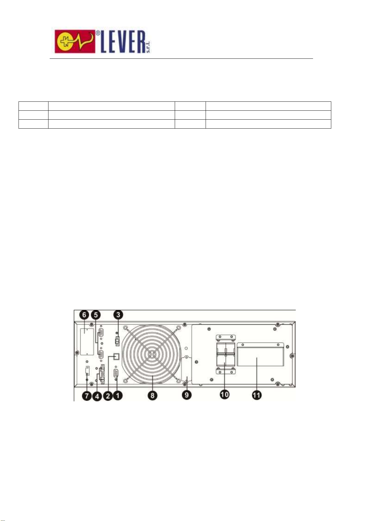
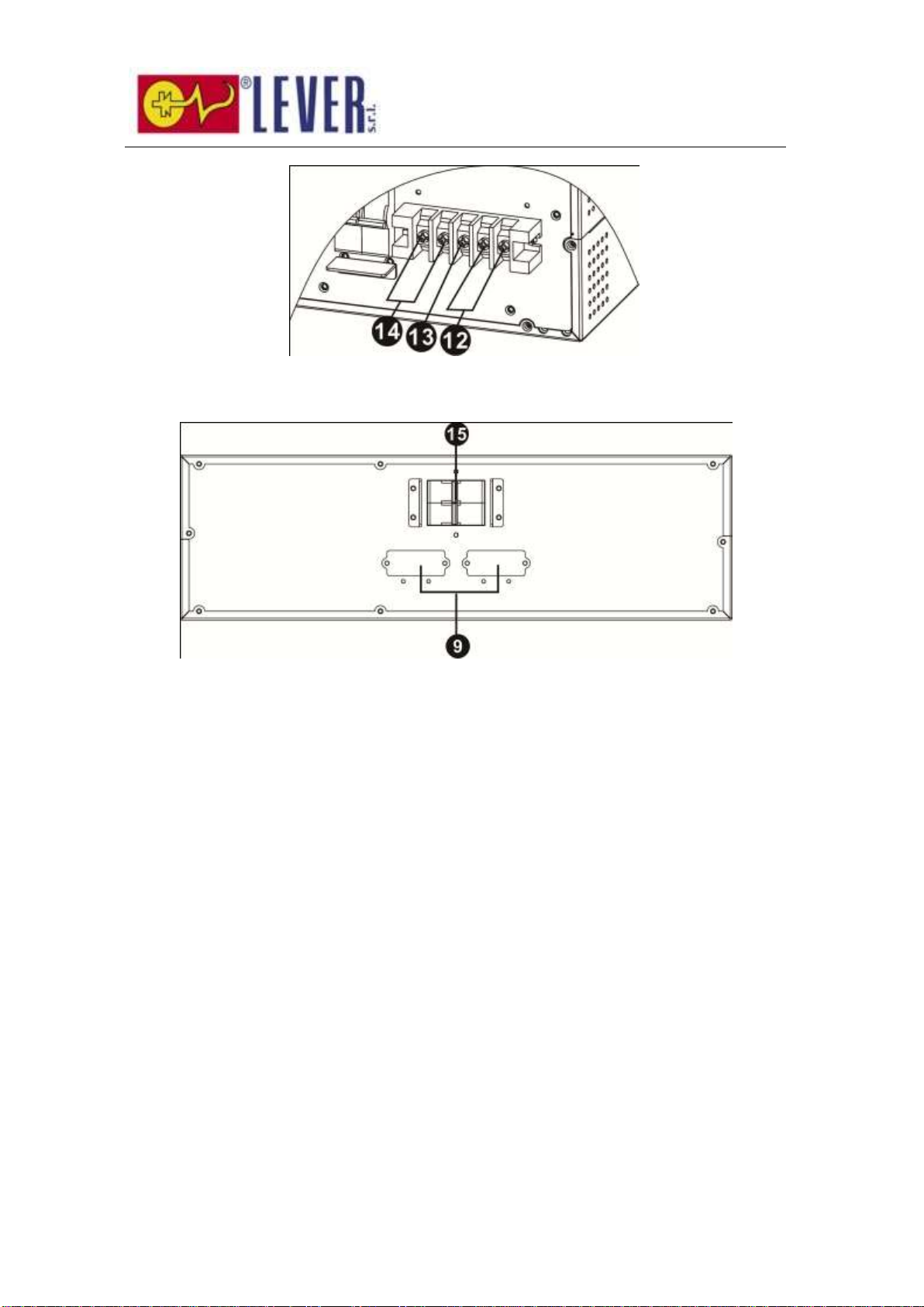
2-2. Rear Panel View ...........................................................................6
2-3. Rack/Tower Installation.................................................................8
2-4. Single UPS Installation..................................................................9
2-5. Parallel UPS Installation .............................................................. 10
3. Operations........................................................................................... 11
3-1. Operating Mode/Status Description.............................................. 11
3-2. Button Operation........................................................................ 11
3-3. LED Indicators............................................................................ 12
3-4. Audible alarm............................................................................. 12
3-5. Single UPS Operation.................................................................. 13
3-6. Parallel UPS Operation ................................................................ 15
3-7. LCD Operation............................................................................ 16
4. Trouble Shooting.................................................................................. 26
4-1. Warning status........................................................................... 26
4-2. Fault mode................................................................................. 26
4-3. Trouble shooting table ................................................................ 26
5. Storage and Maintenance ..................................................................... 29
5-1. Storage...................................................................................... 29
5-2. Maintenance .............................................................................. 29
6. Specifications....................................................................................... 63

4
1. Safety and EMC instructions
Please read carefully the following user manual and the safety instructions before installing the unit or using the
unit!
1-1. Transportation and Storage
Please transport the UPS system only in the original package to protect against shock and impact.
The UPS must be stored in the room where it is ventilated and dry.
1-2. Preparation
Condensation may occur if the UPS system is moved directly from cold to warm environment. The
UPS system must be absolutely dry before being installed. Please allow at least two hours for the UPS
system to acclimate the environment.
Do not install the UPS system near water or in moist environments.
Do not install the UPS system where it would be exposed to direct sunlight or nearby heater.
Do not block ventilation holes in the UPS housing.
1-3. Installation
Do not connect appliances or devices which would overload the UPS (e.g. big motor-type
equipment)).
Place cables in such a way that no one can step on or trip over them.
Do not block air vents in the housing of UPS. The UPS must be installed in a location with good
ventilation. Ensure enough space on each side for ventilation.
UPS has provided earthed terminal, in the final installed system configuration, equipotential earth
bonding to the external UPS battery cabinets.
The UPS can be installed only by qualified maintenance personnel.
An appropriate disconnect device as short-circuit backup protection should be provided in the
building wiring installation.
An integral single emergency switching device which prevents further supply to the load by the UPS
in any mode of operation should be provided in the building wiring installation.
Connect the earth before connecting to the building wiring terminal.
Installation and Wiring must be performed in accordance with the local electrical laws and

5
regulations.
1-4. Operation
Do not disconnect the earth conductor cable on the UPS or the building wiring terminals in any time
since this would cancel the protective earth of the UPS system and of all connected loads.
If the external battery cabinet is connected, the UPS output Anderson connector may be electrically
live even if the UPS system is not connected to the building wiring outlet.
In order to fully disconnect the UPS system, first press the “OFF” button and then disconnect the
mains.
Ensure that no liquid or other foreign objects can enter into the UPS system.
The UPS can be operated by any individuals with no previous experience.
1-5. Standards
* Safety
IEC/EN 62040-1
* EMI
Conducted Emission...............................:IEC/EN 62040-2
Category C3
Radiated Emission..................................:IEC/EN 62040-2
Category C3
*EMS
ESD.........................................................:IEC/EN 61000-4-2
Level 4
RS........................................................ ...:IEC/EN 61000-4-3
Level 3
EFT......................................................... :IEC/EN 61000-4-4
Level 4
SURGE................................................... :IEC/EN 61000-4-5
Level 4
CS........................................................... :IEC/EN 61000-4-6
Level 3
Power-frequency Magnetic field.............. :IEC/EN 61000-4-8
Level 4
Low Frequency Signals............................:IEC/EN 61000-2-2
Warning: This is a product for commercial and industrial application in the
second environment-installation restrictions or additional measures may be
needed to prevent disturbances.

6
2. Installation
There are two types: standard and long-run models. Please refer to the following model table.
Model
Type
Model
Type
6K
Standard model
6K-SC
Long-run model
10K
Standard model
10K-SC
Long-run model
2-1. Unpacking and Inspection
Unpack the package and check the package contents. The shipping package contains:
● One UPS
●One user manual
● One monitoring software CD
●One RS-232 cable (option)
●One USB cable
●One parallel cable and one share current cable (option)
● One battery cable (option)
● Two sets of tower stands including feet and extensions
●Mounting ears
NOTE: Before installation, please inspect the unit. Be sure that nothing inside the package is damaged during
transportation. Do not turn on the unit and notify the carrier and dealer immediately if there is any damage or
lacking of some parts. Please keep the original package in a safe place for future use.
2-2. Rear Panel View
Diagram 1: 6K(SC)/10K(SC) Rear Panel

7
Diagram 2: 6K(SC)/10K(SC) Input/Output Terminals
Diagram 3: Battery Pack Rear Panel
1. RS-232 communication port
2. USB communication port
3. EPO (Emergency Power Off) connector
4. Share current port (for parallel function)
5. Parallel port (for parallel function)
6. Intelligent slot
7. EMBS (External Maintain Bypass Switch) port
8. Cooling fan
9. External battery connector
10. Input circuit breaker
11. Input/Output terminal
12. Input terminal
13. Ground
14. Output terminal
15.Battery pack output circuit breaker

8
2-3. Rack/Tower Installation
2-3-1 Tower Installation
The UPS system is shipped with two sets of feet and 6 extensions (2 short extensions plus 4 long extensions) that
can be used to tower install the UPS module in 3U or UPS module with one battery bank in 6U.
Install UPS module in 3U
Assemble two feet and one short extension as
one tower stand shown in step 1. Align the
two stands approximately 35cm apart in step
2. Then, put UPS module in the stands as
shown in step 3.
Step 1 Step 2
Step 3
Install UPS module and one battery bank in
6U
Assemble two feet and two long extensions as
one tower stand shown in step 1. Align the
two stands approximately 35cm apart in step
2. Then, put UPS module and battery bank in
the stands as shown in step 3.
Step 1 Step 2
Step 3

9
2-3-2 Rack Installation
Please follow below steps to mount UPS into 19” rack or rack enclosure.
Step 1: Attach mounting ears to the side mounting
holes of UPS using the screws provided and the ears
should face forward. Please refer to chart 1.
Chart 1
Step 2: Lift the UPS module and slide it into rack
enclosure. Attach the UPS module to the rack with
screws, nuts and washers (user-provided) through
its mounting ears and into the rack rails. Please
refer to chart 2.
Chart 2
2-4. Single UPS Installation
Installation and wiring must be performed in accordance with the local electric laws/regulations and execute the
following instructions by professional personnel.
1) Make sure the mains wire and breakers in the building are enough for the rated capacity of UPS to avoid the
hazards of electric shock or fire.
NOTE: Do not use the wall receptacle as the input power source for the UPS, as its rated current is less than the

10
UPS’s maximum input current. Otherwise the receptacle may be burned and destroyed.
2) Switch off the mains switch in the building before installation.
3) Turn off all the connected devices before connecting to the UPS.
4) Prepare wires based on the following table:
Model
Wiring spec (mm2)
Input
Output
Battery
Ground
6K(SC)
10
10
10
10
10K(Sc)
16
16
16
16
NOTE 1: The cable for 6K(SC) should be able to withstand over 40A current. It is recommended to use
10mm2or thicker wire for safety and efficiency.
NOTE 2: The cable for 10K(SC) should be able to withstand over 63A current. It is recommended to use
16mm2or thicker wire for safety and efficiency.
NOTE 3: The selections for color of wires should be followed by the local electrical laws and regulations.
Warning:
●For standard battery pack, there are one DC breaker to disconnect the battery pack and the UPS. But for
other external battery pack, make sure a DC breaker or other protection device between UPS and external
battery pack is installed. If not, please install it carefully. Switch off the battery breaker before installation.
NOTE: Set the battery pack breaker in “OFF” position and then install the battery pack.
● Pay highly attention to the rated battery voltage marked on the rear panel. If you want to change the
numbers of the battery pack, please make sure you modify the setting simultaneously. The connection with
wrong battery voltage may cause permanent damage of the UPS. Make sure the voltage of the battery pack
is correct.
● Pay highly attention to the polarity marking on external battery connector and make sure the correct battery
polarity is connected. Wrong connection may cause permanent damage of the UPS.
● Make sure the protective earth ground wiring is correct. The wire current spec, color, position, connection and
conductance reliability should be checked carefully.
● Make sure the utility input & output wiring is correct. The wire current spec, color, position, connection and
conductance reliability should be checked carefully. Make sure the L/N site is correct, not reverse and
short-circuited.
2-5. Parallel UPS Installation
For parallel UPS installation, please contact your dealer for more professional support.

11
3. Operations
3-1. Operating Mode/Status Description
Mode/Status
Description
UPS Power On
When UPS is powered on, it will enter into this mode for a few seconds for
initializing the CPU and system.
AC Mode
When the input voltage is within acceptable range, and the UPS is turned on (the
inverter is running), the UPS will provide pure and stable sine wave AC voltage. The
UPS will also charge the battery in AC mode.
ECO Mode
When the input voltage is within voltage regulation range and ECO mode is
enabled, the UPS will bypass voltage to output for energy saving. If the input
voltage is out of the regulation range but it is still within acceptable range of AC
mode, the UPS will transfer to inverter supplying the power to load (similar as AC
mode).
Converter Mode
When input frequency is within 46 to 64Hz, the UPS can be set with a constant
output frequency (50 Hz or 60 Hz) through the inverter. The UPS will still charge
battery at this mode. There is no bypass at this mode.
Battery Mode
When the input voltage is out of the acceptable range or power failure, and the UPS
is turned on (the inverter is running), the UPS will backup power from battery.
Bypass Mode
When input voltage is within acceptable range and bypass is enabled, and the UPS
(inverter) is not turned on or the inverter can’t support the load, the UPS will supply
power to the load through bypass.
Battery Test Mode
When the UPS is in AC mode or Converter mode, and the battery test command is
enabled through LCD or monitoring software, the UPS will start Battery Test. This
operation is used to check the battery status.
Warning Status
If some errors occur in the UPS (but it is still running normally), buzzer will alarm
and warning code will appear in the LCD for trouble shooting.
Fault Mode
When fatal error occurs in the UPS, it will beep continuously and go to fault mode.
It will display fault codes in LCD.
3-2. Button Operation

12
There are 4 buttons on front panel.
3-3. LED Indicators
There are 4 LEDs on front panel to show the UPS working status:
Mode LED
Bypass
Line
Battery
Fault
UPS Power On
Bypass mode
●
○
○
○
AC mode / Converter mode
○
●
○
○
Battery mode
○
○
●
○
Fault mode
○
○
○
●
Battery test mode
○
●
●
○
ECO mode
●
●
○
○
Note: ●means LED is lit; ○means LED is faded; means LED is flashing.
3-4. Audible alarm
UPS status
Buzzer status
Muted
Bypass mode
Beeping once every 2 minutes
Yes
Battery / Battery-test mode (normal battery voltage)
Beeping once every 4 seconds
Yes
Battery / Battery-test mode (low battery voltage)
Beeping once every second
Yes
Fault
Beeping continuously
Yes
Warnings (except overload)
Beeping once every second
No
Overload
Beeping twice every second
No
Button
Function
ON/ENTER
Press this button to turn on the UPS.
Or press it to confirm the selection in the menu.
OFF/ESC
Press this button to turn off the UPS.
Or press it to return to last menu.
UP
Press this button to select the previous item in the menu.
Or press this button to jump to previous page in the screen.
Or press this button to increase the number in the setting.
DOWN
Press this button to select the next item in the menu.
Or press this button to jump to next page in the screen.
Or press this button to decrease the number in the setting.
UP + DOWN
To allow LCD display to rotate 90ºautomatically, press these two buttons at the
same time. This operation is used to configure the UPS in rack or tower display.

13
3-5. Single UPS Operation
3-5-1. Turn on the UPS with utility power supply (to Line mode)
1) Make sure mains input and battery are connected well, and the battery pack breaker is at “ON”position;
Set the external mains input breaker to “ON”position, then the fan will be running and the UPS supplies
power to the loads via bypass; (The UPS is operating in Bypass mode.)
NOTE: When UPS is in Bypass mode, the output voltage comes directly from utility, so the load is not
protected by UPS. To protect the precious load, the UPS should be turned on to Line mode.
2) When LCD is on home page, press the “ON/ENTER” button, LCD will show a prompt page of “Turn On”;
Move the arrow to “Yes” by up or down button, then press “ON/ENTER”, the UPS will be starting up with
beeping once. You could also enter the “control menu” to select the instruction “Turn On” to startup the
UPS. Please refer to the section of “LCD operation”.
3) A few seconds later, the UPS will enter into Line mode; “Line mode” will be displayed on LCD. (In line
mode, if the utility power is abnormal, the UPS will transfer to Battery mode without interruption.)
3-5-2. Turn on the UPS without utility power supply (to Battery mode)
1) Make sure the battery is connected well and the battery pack breaker is at “ON”position;
2) Press the “ON/ENTER” button to start up the internal power, the UPS will enter into bypass mode
without output;
3) When LCD is on home page, press the “ON/ENTER” button, LCD will show a prompt page of “Turn On”;
Move the arrow to “Yes” by up or down button, then press “ON/ENTER”, the UPS will be starting up with
beeping once. You could also enter the “control menu” to select the instruction “Turn On” to startup the
UPS. Please refer to the section of “LCD operation”.
4) A few seconds later, the UPS will enter into Battery mode; “Battery mode” will be displayed on LCD (In
Battery mode, it will shutdown automatically when battery is depleted. If the utility power is restored, it will
auto restart to Line mode.)
3-5-3. Connect devices to UPS
After the UPS is turned on, you can connect devices (load) to the UPS.
1) Turn on the UPS first and then switch on the devices one by one, the LCD panel will display total load
level;
2) If inductive loads needed to be connected, such as a printer, the in-rush current should be calculated
carefully to see if capacity of the UPS can cover due to the huge starting power consumption of this kind
of load;
3) If the UPS is overload, the buzzer will beep twice every second;
4) When the UPS is overload, please remove some loads immediately. It is recommended to have the total
loads connected to the UPS less than 80% of its nominal power capacity for system safety;
5) If the overload time is over duration listed in spec at Line mode, the UPS will automatically transfer to
Bypass mode. After the overload is removed, it will return to Line mode. If the overload time is over

14
duration listed in spec at Battery mode, the UPS will become fault status. At this time, if bypass is
enabled, the UPS will power to the load via bypass. If bypass function is disabled or the input power is
not within bypass acceptable range, it will cut off output directly.
3-5-4. Charge the batteries
1) After the UPS is connected to the utility power, the charger will charge the batteries automatically except
in Battery mode or during battery test;
2) Suggest to charge batteries at least 10 hours before use. Otherwise, the backup time may be shorter
than expected;
3) Make sure the battery numbers setting on the control board (Please refer to the section of changing
battery quantity) is consistent with actual connection.
3-5-5. Battery mode operation
1) When the UPS is in Battery mode, the buzzer will beep according to different battery capacity. Normally,
the buzzer will beep once every 4 seconds in battery mode, but when the battery voltage drops to the
alarm level, the buzzer will beep once per second and the UPS will shut down automatically soon. Users
could switch off some non-critical loads to disable the shutdown alarm and prolong the backup time. If
there is no more load to be taken off at that time, you have to shut down all loads as soon as possible to
protect the devices or save data. Otherwise, there is a risk of data loss or load failure;
2) In Battery mode, if buzzer sounds annoying, you could enter ”Control->Mute” on LCD to silence it.
Please refer to the section of “LCD operation”;
3) The backup time of the long-run model depends on the external battery capacity;
4) The backup time may change under different environment temperature and load type;
5) The maximum backup time is limited by default 16.5 hours (After discharging 16.5 hours, UPS will shut
down automatically to protect the battery). The time could be modified through LCD panel or
communication port.
3-5-6. Test the batteries
1) If you need to check the battery status or performance when the UPS is running in Line / Converter / ECO
mode, you could enter ”Control->Batt Test” to instruct the UPS to do battery test. Please refer to the
section of “LCD operation”;
2) Users also can set battery test through monitoring software;
3) If the UPS is in battery testing, “Battery test mode” will be displayed on LCD, the buzzer indication will be
the same as Battery mode, but both line LED and battery LED will be lit.
3-5-7. Turn off the UPS with utility power supply in Line mode
1) When LCD is on home page, press the “OFF/ESC” button, LCD will show a prompt page of “Turn Off”;
Move the arrow to “Yes” by up or down button, then press “ON/ENTER”, the UPS will be turning off to
bypass mode with beeping once. You could also enter the “control menu” to select the instruction “Turn
Off” to turn off the UPS. Please refer to the section of “LCD operation”;
NOTE: Here, “Turn Off” means that UPS is not working on line / converter / ECO / battery / battery test
mode. So even though the UPS is turned off, if input or bypass voltage is normal, the internal power

15
supply will be still working; and if bypass status has been set to “enable”, the output voltage of the UPS
will be still exist;
2) If you need to fully cut off the output, please switch off the external input breaker. A few seconds later,
there is no display shown on the panel and UPS is completely off.
3-5-8. Turn off the UPS without utility power supply in Battery mode
1) When LCD is on home page, press the “OFF/ESC” button, LCD will show a prompt page of “Turn Off”;
Move the arrow to “Yes” by up or down button, then press “ON/ENTER”, the UPS will be turning off to
bypass mode with beeping once. You could also enter the “control menu” to select the instruction “Turn
Off” to turn off the UPS. Please refer to the section of “LCD operation”;
2) If there is no bypass input voltage, the UPS will cut off all power supply and there is no display shown on
the panel.
3-5-9. Changing battery quantity (number)
The default battery (12V) quantity of this UPS system is 20 (for one series), but 18, 19 could also be applied in
this system. However, before changing the battery quantity, the UPS should be fully shutdown and the cabinet
cover should be removed, and the jumpers on the control board should be re-set as below table:
Note:1 =
insert with
jumper; 0
= no
jumper; x
= these
pins are
for other functions.
NOTE: This operation should be done by professional technicians, please contact the dealer for support
3-6. Parallel UPS Operation
For parallel UPS operation, please contact your dealer for more professional support.
Battery Number
(one series)
JP1 on control board
pin1 & pin2
pin3 & pin4
Pin5 & pin6
pin7 & pin8
18
X
X
0
0
19
X
X
1
0
20
X
X
1
1

16
3-7. LCD Operation
The entire LCD structure is demonstrated as diagram below:
Main Interface
Control
Measurement
Information
Setting
Alarm
Page 1: Input
Page 2: Output
Page 3: Battery
Page 4: Bypass
Page 5: Charger
Turn On
Batt Test
Mute
Para Unlock
Page 1: Bypass
Page 2: ECO
Page 3: Output
Page 4:Battery
Page 5: UPS Info
Page 6: Others
Fault Info
Warning Info
Bypass
ECO
Output
Battery
Calibration
Others
Press button“Enter”
Press button“Enter”
Press button“Enter”
Press button“Enter”
Press button“Enter”
Press button“ESC”
Press either button“UP”or “DOWN”
Press button“Esc”
Press button“Esc”
Press button“Esc”
Press button“Esc”
Press button“Esc”

17
3-7-1. Main interface (home page)
1) In the first line, it will display the UPS running status mode;
2) When alarms happen, the warning or fault information will display below the “load” line;
3) When the front panel is not operated for 10 minutes, the display page will return back to home page;
4) Press the “UP” or “DOWN” button to enter the operation menu (see 3-7-2-1);
5) When it displays home page in LCD, if UPS is in bypass, you could press the “ON/ENTER” button to turn on
the UPS to AC / converter / ECO / battery mode according to the setting and input status; in reverse, you
could press the “OFF/ESC” button to allow UPS to bypass mode or shut down. (Refer to section of “Single UPS
Operation”).
3-7-2. Operation menu
3-7-2-1. Main menu
→
1) After pressing the “UP” or “DOWN” button at the home page, it will display five items in operation menu:
Control / Measurement / Information / Setting / Alarm.
2) Press “UP” or “DOWN” button to select item;
3) Press “ON/ENTER” button to confirm the selection;
4) Press “OFF/ESC” button to return back to home page;

18
3-7-2-2. Control
NOTE 1: “Para Unlock” appears only when parallel communication failure happens.
NOTE 2: “Turn On” will be displayed if UPS is not turned on. “Turn Off” will be displayed if UPS is turned on.
Generally speaking, these two messages will not be displayed at the same time or in all operation modes.
1) Turn On/Turn Off
This item is for turning on/off the UPS;
a) On Bypass mode, it will display “Turn On” in control menu. If it is selected and confirmed, the UPS will
transfer to AC mode or converter mode or ECO mode or battery mode according to the setting and input
status.
→→
NOTE: You may simply turn on UPS by pressing “ON/ENTER” button in home page. It’s not necessary to
enter control menu to turn on the UPS.
b) On AC mode or converter mode or ECO mode or battery mode, it will display “Turn Off” in control menu.
If it is selected and confirmed, the UPS will transfer to bypass mode or shut down.
→→
NOTE: You may simply turn off UPS by pressing “OFF/ESC” button in home page. It’s not necessary to
enter control menu to turn off the UPS.
2) Battery Test

19
It is to check if the UPS could work well in battery mode and test the battery performance. This selection will be
displayed under all UPS modes. However, it couldn’t execute this test in Battery/Fault/Eco mode and reminder will
pop up in the screen. When battery test is selected, the screen will return back to home page with “Battery Test
Mode” displayed on top. If the test is completed, the displayed status will change back to UPS current mode.
→→
3) Mute
It is to mute the buzzer only when UPS is in battery/bypass/fault mode. After the selection is confirmed, it will
return back to home page and mute icon will be displayed. Although this selection will display in other modes,
it can’t be mute alarm and reminder will pop up at the same time.
→→
4) Para Unlock
It’s to allow UPS startup with parallel function. It only appears when the LCD shows the warning of “3F: Para
Protect”. It means the parallel system is in protection and could not startup because of parallel
communication failure. Before restart the parallel system, please confirm this selection first.
NOTE: Before executing this action, you must check if the system cables and connections are connected
correctly and safely. Please read the related contents in the section of trouble shooting.

20
→ →
3-7-2-3. Measurement
Measurement displays the measurement value of the parameters such as voltage / current / frequency / power /
capacity / time etc. Press “UP” or “DOWN” to explore the pages.
3-7-2-4. Information
Information displays all parameter setting value and status. Press “UP” or “DOWN” to explore the pages.
Table of contents
Languages: