SURFACE SPEAKER/MICROPHONE MODULE
Cat. No. 28A00-1
Installation Instructions
INSTALLATION ENGLISH
DI-022-OA281-00A
DESCRIPTION
The Model 28A00-1 is a speaker and microphone assembly mounted in a surface mount enclosure that allows two-way communication with a central station after an alarm, paging
and listening from an on-premises or remote phone, annunciation of alarm and zone by voice, and voice messaging *. It may be used outdoors in weather protected areas such as
overhangs, eaves, etc.
*Voice messaging not available on all systems
INSTALLATION
1. Mount the backbox to a 4" electrical box, a single gang electrical box, or directly to surface of a wall using provided hardware.
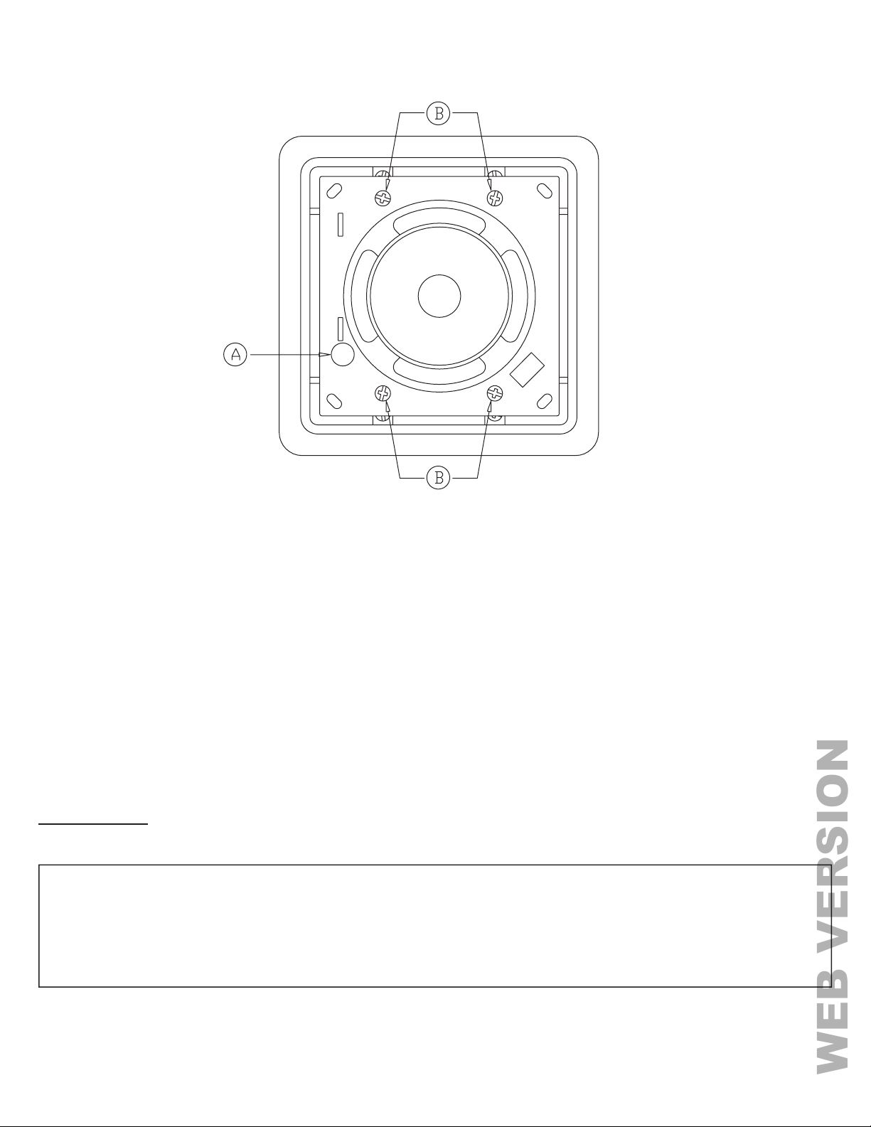
2. Using a screwdriver with a small blade, remove the screw that holds the grille to the speaker/microphone assembly.
3. Place the screwdriver in the slots (top and bottom on the rear of the speaker/microphone assembly) to remove the speaker grille.
4. Connect the wire from the Speaker (Output) on the Two-Way Voice Module to the (+) terminal on the speaker.
5. Connect the wire from the Speaker (Common) on the Two-Way Voice Module to the (-) terminal on the speaker.
6. Route the microphone wires from the Two-Way Voice Module through the hole in the speaker/microphone assembly marked "A" in Figure 2.
7. Connect the wire from the Microphone (+) on the Two-Way Voice Module to the Red microphone wire.
8. Connect the wire from the Microphone (Common) on the Two-Way Voice Module to the Black microphone wire.
SPECIFICATIONS
Speaker Type: Polypropylene Weather Resistant
Voice Coil: 8 Ohms
Power Rating: 15 Watts
Microphone: Electret Condenser, Omni-Directional
Housing and Enclosure Material: UL-94 Flame Retardant Plastic
Color: Decorator White
Dimensions: 5 3/16" H x 5 3/16" W x 2 5/8 D
Hardware: 14 Mounting Screws and 8 Wall Anchors
Enclosure Knockouts Knockouts for wire and plastic duct
WARNINGS AND CAUTIONS
•Read and understand all instructions. Follow all warnings and instructions marked on the product.
•Do not use this product near water - e.g., near a tub, wash basin, kitchen sink or laundry tub, in a
wet basement, or near a swimming pool.
•Never push objects of any kind into this product through openings, as they may touch dangerous
voltages.
•SAVE THESE INSTRUCTIONS.
WARNINGS AND CAUTIONS
•Never install communications wiring or components during a lightning storm.
•Never install communications components in wet locations unless the
components are designed specifically for use in wet locations.
•Never touch uninsulated wires or terminals unless the wiring has been
disconnected at the network interface.
•Use caution when installing or modifying communications wiring or
components.
(28I00-1)
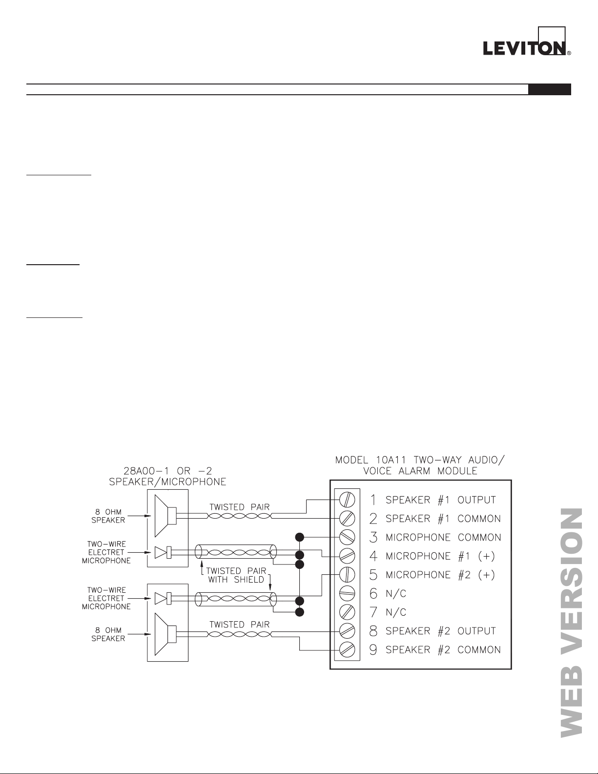
FIGURE 1 – Speaker/Microphone Connections
Microphones should be connected with 24 AWG or larger, shielded twisted pair wire. Wire length should not exceed 100 feet. Connect the cable shields and negative wires together at
the Model 10A11 terminal block only. Do not connect the shield on the microphone end. Additional microphones can be connected to each input in parallel.
Speakers should be connected with 18 AWG or larger, twisted pair wire. For wire runs that exceed 50 feet, use 16 AWG wire or larger. Wire length should not exceed 100 feet.
Additional speakers can be connected to each output in series.