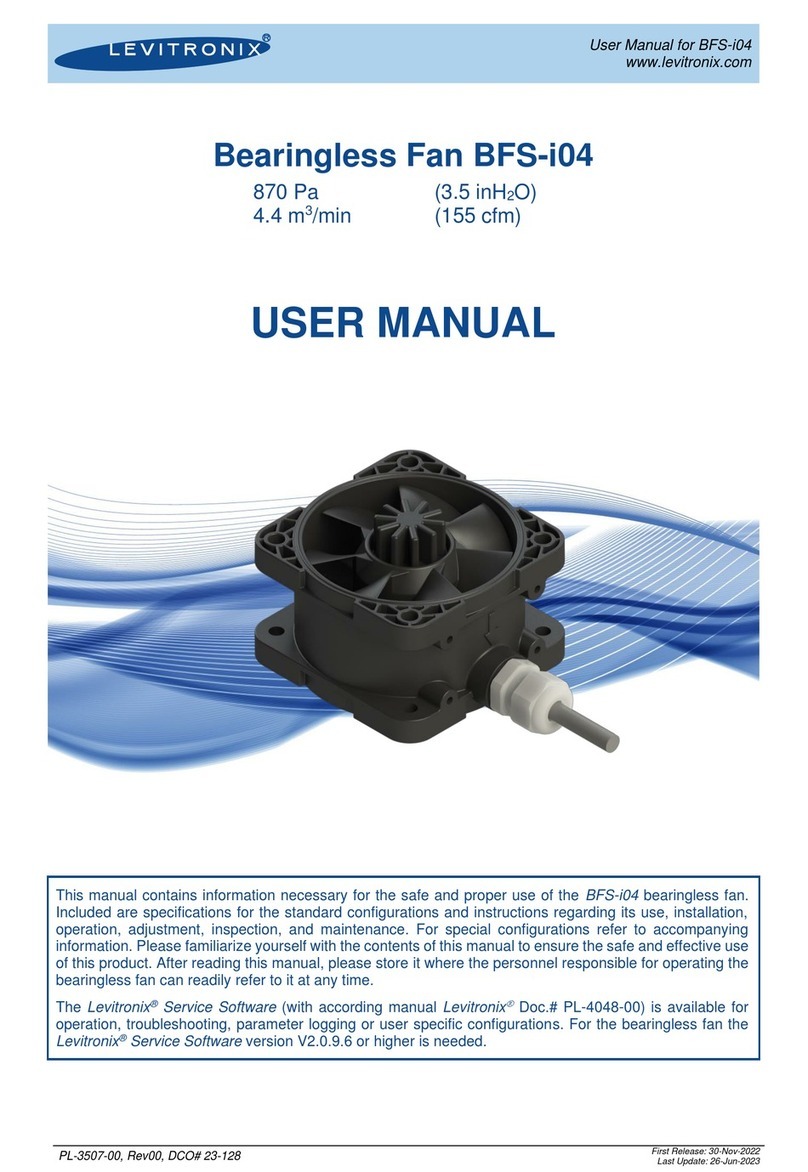
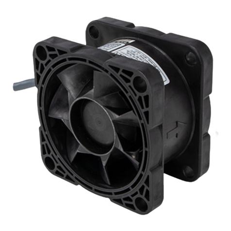
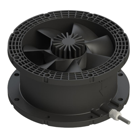
Levitronix BFS-i10 User manual

User Manual for BFS-i10
www.levitronix.com
PL-3505-00, Rev02, DCO# 23-098
First Release: 19-Jan-2021
Last Update: 25-May-2023
Bearingless Fan BFS-i10
1150 Pa
40 m3/min
(4.6 inH2O)
(1413 cfm)
USER MANUAL
This manual contains information necessary for the safe and proper use of the BFS-i10 bearingless fan.
Included are specifications for the standard configurations and instructions regarding its use, installation,
operation, adjustment, inspection, and maintenance. For special configurations refer to accompanying
information. Please familiarize yourself with the contents of this manual to ensure the safe and effective
use of this product. After reading this manual, please store it where the personnel responsible for operating
the bearingless fan can readily refer to it at any time.
The Levitronix®Service Software (with according manual Levitronix
Doc.# PL-4048-00) is available for
operation, troubleshooting, parameter logging or user specific configurations. For the bearingless fan the
Levitronix®Service Software version V2.0.8.0 or higher is needed.

User Manual for BFS-i10
www.levitronix.com
PL-3505-00, Rev02, DCO# 23-098
2
Table of Contents
1SAFETY PRECAUTIONS........................................................................................................3
2SPECIFICATIONS...................................................................................................................4
2.1 Specification of Components............................................................................................................. 4
2.2 System Configuration ........................................................................................................................ 6
2.2.1 Standard System Configuration.....................................................................................................................6
2.2.2 System Configuration ATEX / IECEx.............................................................................................................6
2.3 Basic Dimensions of Main Components............................................................................................ 7
2.4 General Environmental Conditions.................................................................................................... 8
2.5 Pressure-Flow Curves ....................................................................................................................... 9
3ENGINEERING INFORMATION............................................................................................10
3.1 Power Supply and Consumption ..................................................................................................... 10
3.1.1 Power Consumption....................................................................................................................................10
3.1.2 Power Supply..............................................................................................................................................11
3.1.3 Inrush Current .............................................................................................................................................12
3.2 Sound Pressure Level ..................................................................................................................... 12
4INSTALLATION ....................................................................................................................13
4.1 Electrical Installation........................................................................................................................ 13
4.1.1 Installation Instructions for Power Supply and PLC Interface Signals .........................................................13
4.1.2 Electrical Schematics Overview of Motor Interface .....................................................................................16
4.2 Mechanical Installation .................................................................................................................... 17
4.2.1 Flange Sealing Recommendation ...............................................................................................................17
4.2.2 Mounting Proposals.....................................................................................................................................18
4.3 Installation Examples with Interface Panel...................................................................................... 19
5OPERATION .........................................................................................................................20
5.1 Operation of Bearingless Fan.......................................................................................................... 20
5.2 Operation for ATEX / IECEx Application ......................................................................................... 20
6TROUBLESHOOTING AND SUPPORT................................................................................21
6.1 Troubleshooting for Operation with PLC ......................................................................................... 21
6.2 Troubleshooting with Service Software ........................................................................................... 21
6.3 Technical Support............................................................................................................................ 21
7APPENDIX ............................................................................................................................22
7.1 Regulatory Status ............................................................................................................................ 22
7.1.1 CE / UKCA Marking.....................................................................................................................................22
7.1.2 ATEX / UKEX / IECEx Certification and Marking.........................................................................................22
7.1.3 Disposal of Equipment –WEEE Directive 2012/19/EU ...............................................................................22
7.2 Symbols and Signal Words.............................................................................................................. 23

User Manual for BFS-i10
www.levitronix.com
PL-3505-00, Rev02, DCO# 23-098
3
1 Safety Precautions
The BFS-i10 bearingless fan is designed to be used in industrial production machines and equipment
containing ventilation circuits. Typical applications are semiconductor and chemical manufacturing equipment.
Installation shall be done by qualified personnel only. The following safety precautions and all “CAUTION”,
“WARNING” and “DANGER” indications in the relevant sections shall be followed.
CAUTION
Do not under any circumstances open the fan. Levitronix®does not assume
responsibility for any damage occurring under such circumstances.
CAUTION
High magnetic field strength of fan rotor
The fan rotor contains magnets with high field strength. This may alter or
damage the calibration of sensitive electronic devices and measuring
instruments in the immediate surroundings. Keep at a safe distance from
computers, monitors and all magnetic data storage media (e.g. disks, credit
cards, audio and video tapes etc.).
CAUTION
Revolving fan rotor
The fan rotor operates at high rotational speeds. It may cause injury if fingers,
hands, hair, clothes, etc. are getting in touch with the revolving fan rotor. Do not
touch the fan rotor while it is moving.
!
WARNING
Hazardous voltage may be present
In case of usage of an inadequate AC/DC power supply, mains voltages may be
present (even if the system is designed for 48 VDC). The usage of a galvanically
separated power supply, which is certified by a 3rd party (UL or CE), is required.
Do not under any circumstances open the powered fan.
!
WARNING
High magnetic field strength of fan rotor if removed from motor
The fan rotor contains magnets with high field strength. If removed from motor,
pacemakers may be influenced, and magnetic forces may lead to contusions.
Only remove rotor if necessary. Keep distance to pacemakers and handle fan
rotor with care.
!
WARNING
TOXIC CHEMICALS may be present
When using the system to ventilate chemicals, skin contact and toxic gases may
be hazardous to your health. Wear safety gloves and other appropriate safety
equipment.
!
WARNING
Bearingless fan for ATEX / IECEX applications
Only specific types of the bearingless fan are classified for the use in Ex
classified locations. Refer to the corresponding section in the manual.

User Manual for BFS-i10
www.levitronix.com
PL-3505-00, Rev02, DCO# 23-098
4
2 Specifications
2.1 Specification of Components
Figure 1: Standard fan
Figure 2: Accessories
1
2a
E
F
C
B
D
A
A
B
C
D
4
5
9
10
6
7
8
3
2b

User Manual for BFS-i10
www.levitronix.com
PL-3505-00, Rev02, DCO# 23-098
5
Pos.
Component
Article Name
Article #
Characteristics
Value / Feature
1
Bearingless Fan
(ATEX / IECEx)
BFS-i10.1 (5 m)
BFS-i10.1-30 (3 m)
100-10207
100-10208
Voltage, Power Input
48 V DC ±10%, 900 W
(Option: 24 V DC ±5%, 150 W, with reduced max. speed of 4000 rpm)
Max. Pressure, Max. Flow
1150 Pa (4.6 inH2O), 40 m3/min (1413 cfm)
Point of Max. Power
1070 Pa, 33 m3/min, 7400 rpm
(optional 24 V supply voltage: 275 Pa, 20 m3/min, 4000 rpm)
ATEX / IECEx Marking
1258 2503
II 2G Ex h mb IIC T6 Gb
II 2D Ex h mb IIIC T85 °C Db
Ambient and gas temperature range 0 to 40 °C
IP Rating
IP67
Electrical Interfaces
PLC with 2 analog inputs 4-20 mA
1 analog output 4-20 mA
2 digital inputs 0-24 V (optocoupler)
2 digital outputs 0-24 V / 100 mA (open drain)
RS485 interface, Modbus protocol (extended control or service through
fieldbus or Levitronix®Service Software)
Standard Firmware
V4.48
Mechanical Interface
Flange on both motor sides with mounting holes 8 x Ø 11 mm on
diameter 240 mm. Flange inside Ø 200 mm, outside Ø 262 mm
Cable Length
5/3 m + 0.2 m wires with TE connectors for power and PLC signals
Materials
Polypropylene, electrically conductive, flame retardant
Cable: PVC jacket, PVDF bushing
Weight
4.5 kg, 10 lb (for 5 m version)
Table 1: Specification of standard configuration
Pos.
Component
Article Name
Article #
Characteristics
Value / Feature
2a
Adaptor Cable Power
ICP-6.1-03 (0.3 m)
190-10499
Specifications
PVC insulated open wires (3 x 3.3 mm2) with TE connector
Purpose
Connection of fan cable to DC power supply
2b
Adaptor Cable Signals
ICS-5.1-03 (0.3 m)
ICS-5.1-15 (1.5 m)
190-10464
190-10491
Specifications
PVC insulated open wires (12 x 0.14 mm2) with TE connector
Purpose
Connection of fan cable to PLC signals and RS485 fieldbus
3
AC/DC Power Supply
See section 3.1.2 for a list of compatible and tested power supplies.
4
Interface Panel
FIP-2.1
100-91659
Structure/Design
DIN-rail mountable PCB with connectors for:
- 4 x Signal for BFS-i10 fans (TE Connectivity 1-1827875-6)
- 1 x Power supply connector (Wago 2624-3105)
- 22 x PLC push-in (analog/digital inputs/outputs, RS485)
- 1 x Circular COM for LUI-B.1 or USB-RS485 adaptor
Purpose
Easy wiring of PLC signals for up to four BFS-i10 fans, see section 4.3
for further information
5
User Panel
LUI-B.1-06
100-30549
Specifications
Firmware A8.00, IP65, 5 to 24 V supply voltage
Purpose
Control of fan via handheld device with display and menu buttons.
6
USB-RS485 Adaptor
YN-485I-TR
100-30392
Structure/Design
USB connector (A) with termination resistor and cable (2 m) with
connector pair (B and C) for external RS485 wire connection.
Magnetically isolated. Included is a USB space saver cable (D).
Purpose
Control or service of fan via USB port of a PC with Levitronix® Service
Software
7
IP Adaptor Cable
Signal 6 Wires
ICS-1.1-10 (1 m)
ICS-1.1-30 (3 m)
190-10344
190-10345
Specifications
PVC jacket, connectors: circular to circular type
Purpose
Connection of user panel (LUI-B.1) to interface panel (FIP-2.1)
8
IP Adaptor Cable
Signal 6 Wires
ICS-1.2-10 (1 m)
ICS-1.2-50 (5 m)
190-10440
190-10346
Specifications
PVC jacket, connectors: circular type to screw type
Purpose
Connection of user panel (LUI-B.1) to adaptor cable (ICS-5.1) and 5 to
24 V supply
9
IP Adaptor Cable
Signal 6 Wires
ICS-1.3-50 (5 m)
190-10389
Specifications
PVC jacket, connectors: circular type to screw type
Purpose
Connection of interface panel (FIP-2.1) to USB adaptor (YN-485I-TR)
10
ATEX Cable
Sealing System
ACS-A.1
(Roxtec)
100-90292
Materials
Sleeve (A) and Gasket (B): Stainless Steel, EPDM
Frame(C) and 2x Cable Module (D): Roxylon (EPDM Rubber)
Note
Lubricant (E) and measurement plates (F) are included
Table 2: Specification of standard accessories

User Manual for BFS-i10
www.levitronix.com
PL-3505-00, Rev02, DCO# 23-098
6
2.2 System Configuration
2.2.1 Standard System Configuration
Figure 3: Standard system configuration (left) and connection with open wire adaptors (right)
Note: Connection options (right of dashed line) are interchangeable with Figure 4
2.2.2 System Configuration ATEX / IECEx
Figure 4: ATEX / IECEx system configuration (left) and connection with interface panel (right).
Note: Connection options (right of dashed line) are interchangeable with Figure 3
Integrated
Motor and
Electronics
Gas
In
Gas
Out
Mounting
Flange
Tubing
Flow or Pressure Sensor
(optional, not included)
Cable
Bushing
Gasket
(not included)
Impeller
MagLev Fan
Motor Cable
Chemical Resistance
and IP-67 Space
1
Signal Cable
8
User Panel
5
RS485 / USB Converter 6
PC Connection:
- System configuration
- Firmware update
- Monitoring
AC/DC
Power Supply
DC
Out AC
In
3
Screw type connector for open
wires included in cable packages
Adaptor Cable
Power
2b
RS485:
Connect either User Panel,
PC or fieldbus
Signal Interface
- 2 Digital Inputs
- 2 Digital Outputs
- 2 Analog Inputs
- 1 Analog Output
- RS485 Interface
DC Supply
- +VDC
- GND
- Earth
Adaptor Cable
Signal
5 to 24 VDC
2a
Integrated
Motor and
Electronics
Gas
In
Gas
Out
Mounting
Flange
Tubing
Flow or Pressure Sensor
(optional, not included)
Cable
Bushing
Gasket
(not included)
Impeller
MagLev Fan
Motor Cable
Ex conform cable
sealing system
Ex Location
Outside of Fan:
Zone 1/21 or
Zone 2/22 or
Non-Classified
Chemical Resistance
and IP-67 Space
Ex Location
Inside of Fan:
Zone 1/21 or
Zone 2/22
1Signal Cable 7
Signal Cable
9
User Panel
5
RS485 / USB Converter 6
PC Connection:
- System configuration
- Firmwareupdate
- Monitoring
AC/DC
Power Supply
DC
Out AC
In
3
4
10
Cable Adapter
Power
2a
Fan
1
PLC Interface
Supply
Fan
2
Fan
3
Fan
4
PLC Interface
COM
4 x PLC Connection
2 x Analog Input
1 x Analog Output
2 x Digital Input
RS485 interface
forfieldbus
Easy coupling of
multiple fans for
serial or parallel
operation
Interface Panel
Easy andquick wiring of
up to 4 fans

User Manual for BFS-i10
www.levitronix.com
PL-3505-00, Rev02, DCO# 23-098
7
2.3 Basic Dimensions of Main Components
For other configurations, components or more details refer to the according drawings.
Figure 5: Basic dimensions in mm [in] of bearingless fan BFS-i10.1
Note: Non-tolerated dimensions are for reference only, dimensions in inch are rounded only
Figure 6: Basic dimensions of adaptor cables ICP-6.1-03 and ICS-5.1-03
Minimum Cable Bending Radius:
Permanent Installation: 5 x cable OD ( 52 mm [2.05 in])
Sometimes Moved: 10 x cable OD (104 mm [4.09 in])
Cables are not suited for sustained dynamic bending and movement
Standard Cable Configuration:
A = 5.00 m [196.85 in]
B = 0.20 m [7.87 in]
Signal Wires
(PLC, RS485):
0.14 mm2, PVC
Connector Power:
TE D5200S 1-179958-3
DC Supply
Power Wires:
2.5 mm2, PVC
Connector Signal:
TE D1200 1-1827864-6
Motor Cable:
PVC, gray
Cable Bushing:
PVDF with TPE-sealing
and FKM flatsealing ring
Housing and Rotor:
PP, electrically conductive,
flame retardant
Mounting Flange
Sealing Surface
1
2a
2b

User Manual for BFS-i10
www.levitronix.com
PL-3505-00, Rev02, DCO# 23-098
8
Figure 7: Basic dimensions of interface panel FIP-2.1
Figure 8: Basic dimensions of user panel LUI-B.1
2.4 General Environmental Conditions
Condition
Limits
Usage
Indoor
Altitude
Up to 2000 m
Operating ambient temperature
0 to 40°C
Storage ambient temperature
(Extremes for Transportation)
-20 to 80°C
Operating humidity range (relative humidity)
15 –95% (non-condensing)
Storage humidity range (relative humidity)
(Extremes for Transportation)
15 –95% (non-condensing)
Normal storage conditions
Ambient temp.: 20 to 30°C
Relative humidity: 50% (non-condensing)
DC supply fluctuations
10% of nominal voltage
Transient over-voltages typically present on
the mains supply
Surge immunity according to EN 61000-4-5
(tested together with certified AC/DC power supply)
Pollution degree
2
Table 3: Environmental conditions for bearingless fan
5
4

User Manual for BFS-i10
www.levitronix.com
PL-3505-00, Rev02, DCO# 23-098
9
2.5 Pressure-Flow Curves
Figure 9: Pressure-flow curves of bearingless fan BFS-i10.
Note: Typical values measured for BFS-i10.1
•Pressure Drop Coefficient at 0 rpm: C = 0.0085 (
P = C x Q2, Q = Flow [l/s],
P = Pressure Drop [Pa]).
•48 V / 24 V Supply Voltage: The maximum rotational speed is limited to 7400 rpm for 48 V supply
voltage and 4000 rpm for 24 V supply voltage.
•Negative Rotation Direction: Negative rotational speeds can be enabled in the EEPROM editor of
the Levitronix®Service Software or via Modbus command. This feature can be used to block an
existing flow, as replacement for actively controlled valves. If negative flow needs to be avoided for
safety reasons, it is recommended to install passive check valves or a safety shutdown mechanism to
deactivate the bearingless fan in case of negative flow.
•Serial or Parallel Operation of Multiple Fans: Multiple fans can be used to achieve higher pressure
or flow levels.
a. Serial: Pressure is multiplied by up to the number of fans, while flow remains unchanged.
b. Parallel: Flow is multiplied by up to the number of fans, while pressure remains unchanged.
0 200 400 600 800 1000 1200 1400
0
1
2
3
4
5
0
100
200
300
400
500
600
700
800
900
1000
1100
1200
1300
0 5 10 15 20 25 30 35 40
Flow / cfm
Pressure / inH2O
Pressure / Pa
Flow / m3/min
Atmospheric Pressure: 950 hPa, Air Temperature: 24 C
5000 rpm
4000 rpm
7000 rpm
3000 rpm
6000 rpm
7400 rpm
Stability Limit
(Tilting)
48 V Supply Voltage,
Released Performance
24 V Supply Voltage,
Released Performance
1000 rpm
2000 rpm
0 200 400 600 800 1000 1200 1400
-5.2
-4.2
-3.2
-2.2
-1.2
-0.2
-1300
-1200
-1100
-1000
-900
-800
-700
-600
-500
-400
-300
-200
-100
0
0 5 10 15 20 25 30 35 40
Flow / cfm
Pressure / inH2O
Pressure / Pa
Flow / m3/min
3000 rpm
-4000 rpm
1000 rpm
-6000 rpm
2000 rpm
Stability Limit
(Tilting)
0 rpm
-7400 rpm
48 V Supply Voltage,
Released Performance 24 V Supply Voltage,
Released Performance
4000 rpm
-2000 rpm

User Manual for BFS-i10
www.levitronix.com
PL-3505-00, Rev02, DCO# 23-098
10
3 Engineering Information
3.1 Power Supply and Consumption
3.1.1 Power Consumption
Figure 10: Steady state power consumption vs flow and speed (DC input)
Note: Typical values measured for BFS-i10.1
Figure 11: Peak power consumption during acceleration (DC input)
Note 1: Typical values measured for BFS-i10.1 at operating point with maximum power consumption
Note 2: Dashed line: example of optional input power limitation
0 200 400 600 800 1000 1200 1400
0
100
200
300
400
500
600
700
800
900
1000
0 5 10 15 20 25 30 35 40
Flow / cfm
Power Consumption / W
Flow / m3/min
Atmospheric Pressure: 950 hPa, Air Temperature: 24
5000 rpm
Stability Limit
(Tilting)
Atmospheric Pressure: 950 hPa, Air Temperature: 24
Stability Limit
(Tilting)
Atmospheric Pressure: 950 hPa, Air Temperature: 24
7000 rpm
Stability Limit
(Tilting)
Atmospheric Pressure: 950 hPa, Air Temperature: 24
4000 rpm
3000 rpm
6000 rpm
7400 rpm
Stability Limit
(Tilting)
48 V Supply Voltage,
Released Performance
24 V Supply Voltage,
Released Performance
0
100
200
300
400
500
600
700
800
900
1000
2000 2500 3000 3500 4000 4500 5000 5500 6000 6500 7000 7500
Power Consumption / W
Rotational Speed / rpm
48 V Supply Voltage,
Released Performance
24 V Supply Voltage,
Released Performance
2000 rpm / s 1000 rpm / s 500 rpm / s

User Manual for BFS-i10
www.levitronix.com
PL-3505-00, Rev02, DCO# 23-098
11
•Steady State Power Consumption: Depends on the actual speed, pressure, and flow. Figure 10
visualizes the steady state power consumption for different operating points.
•Peak Power Consumption (short time): Occurs during acceleration and depends on the rotational
speed and the acceleration rate. Figure 11 visualizes the peak power consumption.
•Power Supply Rating: Depending on the operating point, one power supply may be used to power
several bearingless fans simultaneously, or a supply with lower power rating may be used (see also
section 3.1.2).
•Input Power Limitation: An optional input power limit may be set via Levitronix®Service Software or
Modbus protocol. If set, actual acceleration rate and/or maximum speed are reduced dynamically such
that the specified limit is not exceeded (±20 W tolerance). The extent to which they are reduced
depends on the power limit as well as the operating point. The dashed line in Figure 11 shows an
example for 600 W at operating point with maximum power consumption. The fan accelerates with
2000 rpm / s up to 5000 rpm, then gradually reduces the acceleration rate to prevent further increase
in input power. The maximum reachable speed in this operating point at 600 W input power is around
6500 rpm (see also steady state consumption, Figure 10).
3.1.2 Power Supply
It is highly recommended to evaluate used power supplies under demanding operating situations like fast
braking from maximum speed and during power on and take-off of the fan rotor.
The power rating of the supply may be chosen according to the desired operating point / maximum speed /
number of fans per supply –see Figure 10, Figure 11.
Table 4 shows a selection of power supplies tested at Levitronix®with according speed and/or input power
limitations. Please note that only the general functionality of the BFS-i10 in combination with the given supplies
was tested, and no recommendations in terms of reliability, efficiency, certifications, cost effectiveness or
similar are given.
Manufacturer
Article Name
Characteristics
Value / Feature
Recommended Limits
PULS Power
Supplies
QS40.481
Voltage Input / Output
85 –264 V AC (auto. detection) / 48 V DC
- No limit required (1 fan per power supply)
- Example limits for 2 fans per power supply:
Input power limit 700 W (peak)
Speed limit 6000 rpm (continuous)
Power Output continuous / peak
960 W / 1440 W for 4 s
Certification / Standards
CB, UL, CSA, Semi F47
Mean Well
HRPG-1000-48
Voltage Input / Output
85 –264 V AC (auto. detection) / 48 V DC
- No limit required (1 fan per power supply)
- Example limits for 2 fans per power supply:
Input power limit 484 W (peak & continuous)
Speed limit 6000 rpm (continuous)
Power Output
1008 W
Certification / Standards
CB, UL, CSA
TDK Lambda
RWS1000B-48
Voltage Input / Output
85 –265 V AC (auto. detection) / 48 V DC
- No limit required (1 fan per power supply)
- Example limits for 3 fans per power supply:
Input power limit 316 W (peak & continuous)
Speed limit 5000 rpm (continuous)
Power Output
1008 W
Certification / Standards
CB, UL, CSA, Semi F47
Cosel
PJA1000F-48
Voltage Input / Output
85 –264 V AC (auto. detection) / 48 V DC
- No limit required (1 fan per power supply)
- Example limits for 4 fans per power supply:
Input power limit 232 W (peak & continuous)
Speed limit 4500 rpm (continuous)
Power Output
1008 W
Certification / Standards
CB, UL, CSA
Traco Power
TSP-600-148-M
Voltage Input / Output
85 –264 V AC (auto. detection) / 48 V DC
- Recommended limits (1 fan per power supply):
Input power limit 580 W (peak & continuous)
Speed limit 6500 rpm (continuous)
Power Output
600 W
Certification / Standards
CB, UL, CSA, Semi F47
TDK Lambda
RWS600B-48
Voltage Input / Output
85 –265 V AC (auto. detection) / 48 V DC
- Recommended limits (1 fan per power supply):
Input power limit 580 W (peak & continuous)
Speed limit 6500 rpm (continuous)
Power Output
600 W
Certification / Standards
CB, UL, CSA, Semi F47
Traco Power
TIB 480-148
Voltage Input / Output
85 –264 V AC (auto. detection) / 48 V DC
- Recommended limits (1 fan per power supply):
Input power limit 700 W (peak)
Speed limit 6000 rpm (continuous)
Power Output continuous / peak
480 W / 720 W for 4 s
Certification / Standards
CB, UL, CSA, Semi F47
Traco Power
TIB 240-124
Voltage Input / Output
85 –264 V AC (auto. detection) / 24 V DC
- Recommended limits (1 fan per power supply):
Input power limit 340 W (peak)
No speed limit (automatically limited to 4000 rpm,
if 24 V supply is detected
Power Output continuous / peak
240 W / 360 W for 4 s
Certification / Standards
CB, UL, CSA, Semi F47
Table 4: Specification of tested power supplies
Note: Additionally tested and passed, but discontinued by manufacturer: Cosel PLA600F-48 (600 W, limits as stated for other 600 W
supplies)
The following power supplies were tested but failed to recover the DC voltage quick enough during fast braking
and accelerating tests, triggering a shutdown to error state on the fan:
Mean Well RSP-1000-48 / Mean Well SDR-960-48

User Manual for BFS-i10
www.levitronix.com
PL-3505-00, Rev02, DCO# 23-098
12
3.1.3 Inrush Current
The BFS-i10 features an inrush current limitation circuit. A peak value of 25 A with an I2t value of 1.7 A2s was
measured by hot-plugging the BFS-i10 with 5 m cable length to a 1000 W power supply.
3.2 Sound Pressure Level
The sound pressure level emitted by the BFS-i10 depends strongly on the installation, operating point, and
rotational speed. It is recommended that customers measure the sound pressure level after installation of the
fan in their setup during typical operation.
Figure 12 shows the sound pressure levels measured at Levitronix®. The fan was installed at a height of about
2 m above ground into a closed duct system. Measurements were taken based on Semi S2 guidelines, i.e.
1 m traversed from the setup at a height of 1.2 m and 1.5 m above ground.
Figure 12: Sound pressure level vs rotational speed and measurement height
Note: Typical measured values of BFS-i10.1 installed in a closed duct system
50
55
60
65
70
75
80
3000 3500 4000 4500 5000 5500 6000 6500 7000 7500
Sound Pressure Level / dBA
Rotational Speed / rpm
48 V Supply Voltage,
Released Performance
24 V Supply Voltage,
Released Performance
1.5 m above
ground
1.2 m above
ground

User Manual for BFS-i10
www.levitronix.com
PL-3505-00, Rev02, DCO# 23-098
13
4 Installation
4.1 Electrical Installation
!
WARNING
Protective Earth on Ex-Model
Bearingless Fans placed in Ex classified locations must be connected to
protective earth, which must be done with the earth wire according to Table 5.
!
WARNING
Hazardous voltage may be present
Always isolate the electrical power supply before making or changing
connections to the unit.
In case of usage of an inadequate AC/DC power supply, mains voltages
may be present (even if the system is designed for 48 VDC). The usage
of a galvanically separated power supply, which is certified by a 3rd party
(UL or CE), is required.
CAUTION
The analog inputs and analog and digital outputs are not galvanically
isolated from the motor electronics.
4.1.1 Installation Instructions for Power Supply and PLC Interface Signals
•Connection: Table 5 provides an overview of the fan connectors (adaptor cables available as
accessory).
Connect power and desired interfaces to the respective pins and connect the cable shield to earth.
Figure 14 provides a reference for hardware configuration of the PLC inputs and outputs.
•Power requirement: See section 3.1 for the power consumption of the bearingless fan.
•PLC requirement: To operate the bearingless fan with a PLC, a minimum of one analog input is
needed for speed control, or a set of two analog inputs for process (pressure or flow) control. The
analog output can be used to monitor operating parameters. See Table 5 for an overview of the
standard functionality. For in-depth details on the configurability of PLC interface, please refer to the
firmware specification document (standard firmware: SW-3505-00).
•RS485 interface: To use RS485 as a control or service interface, an initialization resistor network
according to Figure 13, Figure 14 should be used to ensure stable communication and avoid
disturbance effects.
For service and debugging purposes with the Levitronix®Service Software an RS485 to USB converter
cable (initialization network included) can be ordered according to Table 2.
Do not use multiple master devices at the same time.
•RS485 Fieldbus Multi-System Arrays: Several systems can be directly connected to the same
RS485 master. See Figure 13.
Address setting of the fan units can be done with the Levitronix®Service Software and a PC.
A termination resistor is recommended for long bus lengths. Do not use closed ring arrangements.
Contact Levitronix®technical support (section 6.3) for further details and support.

User Manual for BFS-i10
www.levitronix.com
PL-3505-00, Rev02, DCO# 23-098
14
Pin
Wire Color
Designation
Description
Standard Levels
Power Connector:
TE D5200S 1-179958-3
Counterpart:
TE D5200S 1-353047-3
1
Red
Power +
Supply
+ 48 VDC ± 10 %
+ 24 VDC ± 5 % (reduced performance)
2
Black
Power -
Supply
Internally connected to cable shield
3
Yellow-green
GND / earth
Cable shield
To be connected to earth
PLC Connector:
TE D1200 1-1827864-6
Counterpart:
TE D1200 1-1903131-6
B4
Pink
Digital input 1
Default: not used
(Configurable: enable / reset)
B5
Gray
Digital input 2
Process / speed mode switch
5…24 V (min. 30 ms) Process mode
0 V / n.c. (min. 30 ms) Speed mode
B3
Yellow
Digital input ground
Reference for digital inputs
B6
Violet
Analog input 1
Setpoint speed / process value
and enable / reset fan
4…20 mA 0…7400 rpm / 0…100 % setpoint
> 3.5 mA (edge triggered) On / reset
B1
Gray-pink
Analog input 2
Actual process value
(pressure or flow sensor)
4…20 mA 0…100 %
B2
Blue
Analog input ground
Reference for analog inputs
A2
Brown
Digital output 1
System status signal
Circuit closed Power output on
Circuit open Power output off
Ground (A4) is reference
A3
White
Digital output 2
Error signal
Circuit closed No errors present
Circuit open System is in error state
Ground (A4) is reference
A1
Blue-red
Analog output
Actual speed
0…7400 rpm 4…20 mA
Ground (A4) is reference
A5
Brown-green
RS485 +
RS485 interface
Modbus protocol
A6
White-yellow
RS485 -
A4
White-green
Ground
Reference for digital and analog
outputs
GND / earth (internally connected to power - and cable
shield)
Table 5: Standard configuration of motor connectors
Note 1: Levels and assignments of analog and digital inputs and outputs are configurable in EEPROM editor of Levitronix®Service
Note 2: Software or through Modbus protocol. See firmware specification (SW-3505-00) for detailed information
Pin
YN-485I-TR
Open wire to USB adaptor
ICS-1.2
Open wire to user panel LUI-B
ICS-1.3
Interface panel FIP to USB adaptor
1
-
RS485+
RS485+
2
-
RS485-
RS485-
3
-
Ground
Ground
4
Ground
-
-
5
RS485-
-
-
6
RS485+
+ 24 VDC supply for LUI-B
-
Table 6: Pin definition of screw type connectors on adaptor cables

User Manual for BFS-i10
www.levitronix.com
PL-3505-00, Rev02, DCO# 23-098
15
Figure 13: Multi-fan system array on RS485 fieldbus
510
W
120
W
3.3..5 V
510
W
120
W
Termination:
Recommended for main bus line > 5 m
Initialization network:
Always recommended, to be implemented atmaster
Master Main bus line: < 100 m. Shielded twistedwires recommended
Branch bus lines: sum of all branch lengths < 33 m
System 1
System 2, 3
System 4, 5, 6
System n

User Manual for BFS-i10
www.levitronix.com
PL-3505-00, Rev02, DCO# 23-098
16
4.1.2 Electrical Schematics Overview of Motor Interface
Figure 14: Electrical schematics of motor interface
Note 1: RS485 to USB converter cable with termination resistors to be ordered according to Table 2
Note 2: Do not use multiple master devices on the RS485 at the same time
Bearingless fan
interface circuit Example of user
interface circuit
240 W
240 W
2.2 kW
A2 / Brown:
Digital output 1
A3 / White:
Digital output 2
B3 / Yellow:
Digital input ground
B5 / Gray:
Digital input 2
B4 / Pink:
Digital input 1
B2 / Blue:
Analog input ground
B6 / Violet:
Analog input 1
B1 / Gray-pink:
Analog input 2
A4 / White-green:
Ground (GND)
A1 / Blue-red:
Analog output
A5 / Brown-green:
RS485+
A6 / White-yellow:
RS485-
3 / Yellow-green:
Cable Shield
GND
4..20 mA
4...20 mA
Personal
Computer
(Service)
5..24 V
200 mA
5..24 V
4..20 mA
Analog inputs not galvanically isolated
Max. pin voltage to GND = 10 V
Pin numbers, wire colors
and wire name
510 W
1 / Red:
48 VDC
2 / Black:
Ground/Earth
120 W
3.3..5 V
56 V 30 A
Analog output not galvanically isolated
Digital outputs not galvanically isolated
2.2 kW
PLC connector
450 W
Tool
Control
510 W
RS485 - USB
Converter
with
Termination
3.3 V
Power connector
AC/DC
Supply
48 VDC

User Manual for BFS-i10
www.levitronix.com
PL-3505-00, Rev02, DCO# 23-098
17
4.2 Mechanical Installation
CAUTION
High magnetic field strength of fan rotor
The fan rotor contains magnets with high field strength. This may alter
or damage the calibration of sensitive electronic devices and measuring
instruments in the immediate surroundings. Keep at a safe distance from
computers, monitors and all magnetic data storage media (e.g. disks,
credit cards, audio and video tapes etc.).
!
WARNING
High magnetic field strength of fan rotor if removed from motor
The fan rotor contains magnets with high field strength. If removed from
motor, pacemakers may be influenced, and magnetic forces may lead
to contusions. Only remove rotor if necessary. Keep distance to
pacemakers and handle fan rotor with care.
!
WARNING
Only specific BFS-i10 bearingless fans are classified for the use in Ex
classified locations. Refer to the corresponding section in the manual.
!
WARNING
In case separation of Ex classified locations is needed at installation, the
relevant safety precautions to fulfill the relevant regulatory requirements
must be considered.
•Ex cable sealing system: An Ex conform solution is needed for the motor cable to leave the Ex area.
One option is an Ex certified cable sealing system as listed in Table 2.
•Rotor handling: The rotor contains permanent magnets which can attract ferromagnetic parts.
Therefore, any ferromagnetic tools and tools with sharp edges should be kept away from the rotor to
avoid injury to personnel and damage to the rotor surface. Do not remove rotor from fan unless
necessary.
•Motor fixation before operation: The motor must be mounted rigidly before operation. The magnetic
bearing is not designed for movement of the fan during operation. Any movement (especially tilting) of
the fan during rotation may lead to a touch-down of the magnetic bearing with potential mechanical
damage to the system.
•Motor fixation, resonances: It should be avoided that the mounting construction can resonate with
the motor. Such resonances will lead to excessive motor currents, heat-up of the system and may lead
to malfunction of the magnetic bearing.
•Motor fixation within ducts: Do not use the fan as a structural element of a duct system. The flange
is not designed to withstand excessive force or torque.
•Mounting holes: The fan can be mounted with eight M10 screws on the inlet flange and eight M10
screws on the outlet flange (see Figure 5).
•Cable bending radius: Minimum cable bending radius according to Figure 5 must be ensured.
4.2.1 Flange Sealing Recommendation
The pressure tightness of the fan flange was successfully tested at Levitronix®with the following reference
setup:
•Flat Gasket: Material FKM, thickness 3 mm, dimensions see Figure 15.
•Flange Counter Part: Material PP, thickness 15 mm.
•Screws: M10 screws, tightening torque 5 Nm.

User Manual for BFS-i10
www.levitronix.com
PL-3505-00, Rev02, DCO# 23-098
18
Figure 15: Flat Gasket Dimensions (mm) used by Levitronix®
4.2.2 Mounting Proposals
BFS-i10 fans can be adapted into many different duct systems and may be operated in parallel or series to
achieve higher flow or pressure. This section shows a few of many possible mounting scenarios. For more in-
depth information contact Levitronix® technical support (section 6.3).
Figure 16: Possible mountings of BFS-i10 in different duct systems
Round duct Square duct 2 fan in series,
up to 2x pressure 2 fans in parallel,
up to 2x flow rate

User Manual for BFS-i10
www.levitronix.com
PL-3505-00, Rev02, DCO# 23-098
19
Figure 17: Examples of mounting with through holes (left) and self-cutting thread inserts (right)
4.3 Installation Examples with Interface Panel
The interface panel FIP-2.1 can be used for easy signal wiring of up to four fans. The panel can be mounted
to a DIN rail. Figure 18 describes two of many possible scenarios. For more in-depth information contact
Levitronix® technical support (chapter 6.3). See section 3.1.2 for the selection of the power supply.
Figure 18: Examples of fan installation with interface panel FIP-2.1
Left: Four fans are connected to a single power supply and controlled individually through fieldbus interface
Right: Two fans are mounted in series and controlled through PLC. The first fan runs in process mode using the feedback from a
pressure or flow sensor, the second fan is configured to match the speed of the first one. They act as one process control unit with
higher pressure performance (the same configuration may be used with fans mounted in parallel to achieve higher flow performance)
Power
input
UI
Power supply
Fieldbus
Power supply Set pressure
or flow
(4..20 mA)
Speed
feedback
(4..20 mA)
Pressure
or flow
sensor
(4..20 mA)
RS485-
RS485+
Ain1
Ain2
Aout
Din1
1Din2
Ain1
Ain2
Aout
Din1
2Din2
Ain1
Ain2
Aout
Din1
3Din2
Ain1
Ain2
Aout
Din1
4Din2
Power
input
UI
RS485-
RS485+
Ain1
Ain2
Aout
Din1
1Din2
Ain1
Ain2
Aout
Din1
2Din2
Ain1
Ain2
Aout
Din1
3Din2
Ain1
Ain2
Aout
Din1
4Din2

User Manual for BFS-i10
www.levitronix.com
PL-3505-00, Rev02, DCO# 23-098
20
5 Operation
CAUTION
Revolving fan rotor
The fan rotor operates at high rotational speeds. It may cause injury if fingers,
hands, hair, clothes, etc. are getting in touch with the revolving fan rotor. Do not
touch the fan rotor while it is moving.
Please consider the following notes for safe and successful operation of the bearingless fan BFS-i10 to prevent
injury to personnel or damage to equipment:
•Mounting: Only activate the bearingless fan if it is firmly mounted to a rigid non-movable structure.
•Mechanical Protection: Only activate the bearingless fan if the rotor is mechanically protected from
reaching into it. Operating the fan without protection might lead to serious personnel injury or damage
to equipment as a result of objects being pulled into the rotor blades.
5.1 Operation of Bearingless Fan
Operation and Interfaces:
•PLC:Control through analog and digital inputs and outputs.
•RS485, Service Software: Control through a PC. Service Software is available from Levitronix®
Technical Service Department (section 6.3), connection cable is available as accessory (section 2.1).
•RS485, Modbus commands: Digital control through superordinate customer control unit.
•RS485, User Panel: Control through the user panel LUI-B.1. Panel and connection cables are
available as accessories (section 2.1).
Fan control modes:
•Closed loop speed control: Internal sensors are used to measure the actual rotational speed to
assure accurate control of the setpoint speed.
•Closed loop process (pressure or flow) control: An external pressure or flow sensor must be
connected to the analog input of the PLC. Control parameters need to be adapted according to the
used sensor (response time, delay, scaling), the placement of the sensor (before/after, distance to fan)
and the setup of the hydraulic circuit. Contact Levitronix®Technical Service Department for assistance
(section 6.3).
Please refer to the firmware specification document for complete details about the operation of the BFS-i10
(document number for standard firmware: SW-3505-00). The document can be requested from Levitronix®
Technical Service Department (section 6.3).
5.2 Operation for ATEX / IECEx Application
Specific precautions may be considered while using the bearingless fan in potentially explosive gas
atmospheres according to ATEX / IECEx category 2G/2D (Zone 1 and 21) or 3G/3D (Zone 2 and 22).
!
WARNING
Operational Temperature 85°C T6
Maximum allowed gas temperature is 40°C / 104°F for the use in Ex
classified applications.
!
WARNING
Do not operate the fan against closed valves
Operation against closed valves might lead to increased gas
temperature.
Other manuals for BFS-i10
1
Table of contents
Other Levitronix Fan manuals
Popular Fan manuals by other brands

Vortice
Vortice ARIANTE TOWER DESCRIPTION AND USE

nilan
nilan Comfort 250 Top installation instructions

Westinghouse
Westinghouse ETL-ES-GW-Contempra-WH22 owner's manual

Craftmade
Craftmade Chalice CL52 Specifications

Vortice
Vortice VORT PRESS 110 I LL Instruction booklet

AERMEC
AERMEC VES030 installation manual