Industrial Ladder Tower Double Width Tower Assembly Guide Industrial Ladder Tower Double Width Tower Assembly Guide
The tower should be manoeuvred into position by hand by
pushing it from the base frame. Never attempt to use any
mechanical equipment (i.e. a forklift etc.) to move the tower.
If it is necessary to lift individual components whilst assembling
the tower, a dependable knot should fasten each item.
Be aware of overhead obstructions – pay particular attention to
any live electrical cables. Ensure that no persons, materials or
tools are on the tower when it is being moved.
Additional care should be taken when moving the tower on
uneven or inclining ground. The use of the castor locks should
be deployed when the tower is in position. When moving the
tower the stabilisers should only be lifted 35mm from ground
level.
Towers under 4m in height are the only towers that
should be moved.
zCheck all components (see component list) are available
and in usable condition.
zDamaged or incorrect components should not be used.
Scale 4. 13 - 18 mph .......................................................................................OK TO WORK ON TOWER
Moderate Breeze: Raises dust, loose paper; moves small branches
Scale 5. 19 - 24 mph ..................................................................................STOP WORKING ON TOWER
Fresh Breeze: Small trees in leaf begin to sway; white crested wavelets form on inland waters
Scale 6. 25 - 31 mph ................................................................................................ DISMANTLE TOWER
Strong Breeze: Large branches in motion; umbrellas used with difficulty; telephone wires “whistle”.
Be aware that wind conditions are a very important consideration when using a tower. Attention must be paid to individual situations
where wind conditions can increase - i.e. when working between buildings, or close to the corner of a building and at open ends.
Never use tarpaulins or similar covers without seeking the correct advice.
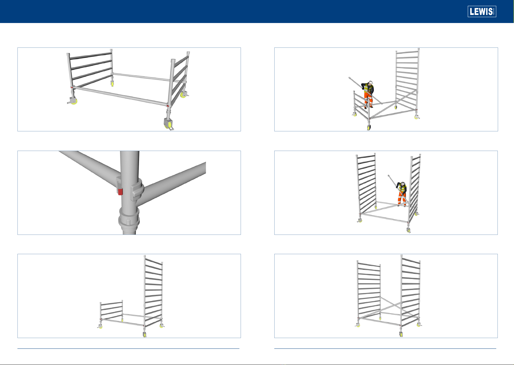
This document will provide all users of Lewis Access Towers with
a complete guide to the erection of the Lewis SW (Double Width)
Aluminium Tower, employing the 3T (Through the Trap) method.
The user should read the entire contents of this document before
commencing assembly and pay particular attention to all of the
safety instructions. If the equipment is passed onto another party
a copy of these instructions should accompany the handover.
Two persons are necessary to carry out the erection of the
equipment detailed in this document. It is strongly recommended
that the following items of personal protection equipment be
worn at all times: safety boots (EN345 or BS1870 / 4972); safety
helmet (EN397 or BS5240); gloves. The SWL (Safe Working
Load) for each platform is 275kg, evenly dispersed.
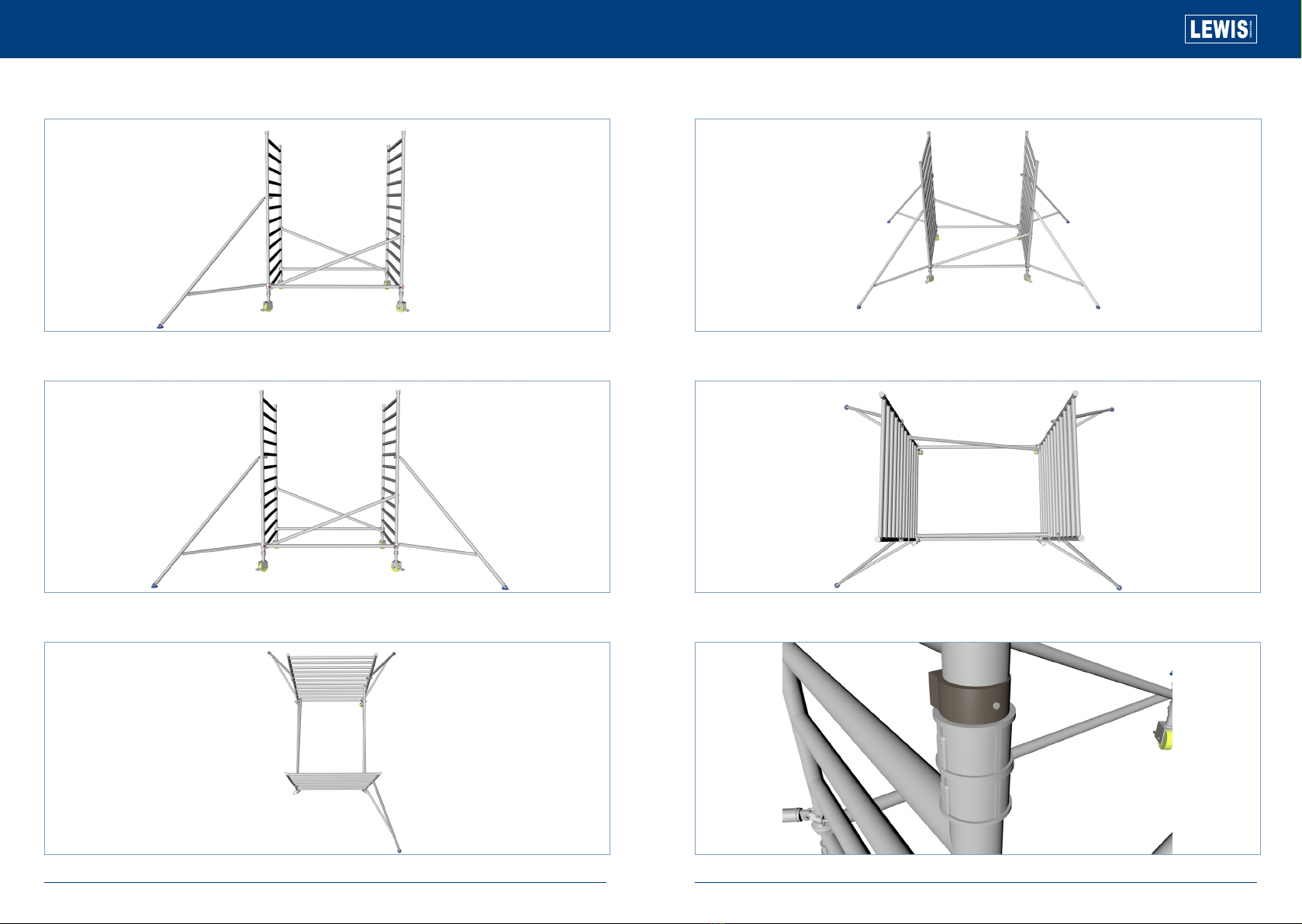
Additional items, such as steps or conventional ladders, must
never be used to gain further height from the platform. The tower
must be climbed from within the structure, on no occasions
should the tower be scaled from the outside. Inspect all the tower
components before each use. Pay particular attention to;
zCastings - check for cracks
zWelds - free from cracks
zTubes/Braces/Rungs - Straight and with indents less than
5mm deep
zPlatforms - no damage, free from debris
zCastors - moves freely, threads free from damage, brake
working
zOutriggers - straight, feet flat
zInspect the equipment for damage regularly, at least daily.
Double Width Tower Assembly Guide
The Lewis Tower is a Class 3 Industrial Tower System
Working on the Tower - The Beaufort Windscale
zIf damage should occur whilst in use, stop work
immediately and isolate the damaged items from the rest of
the tower and contact your supplier.
zCheck the ground on which the tower is to be used is
relatively flat, smooth and capable of supporting the tower.
zThe SWL (Safe Working Load) of the tower is 275kg per
platform, inc the weight of the tower - evenly distributed, up
to a maximum of 950kgs per tower.
zDo not exceed the SWL.
zNever attach safety harnesses or similar safety equipment
to the tower whilst erecting or dismantling the tower.
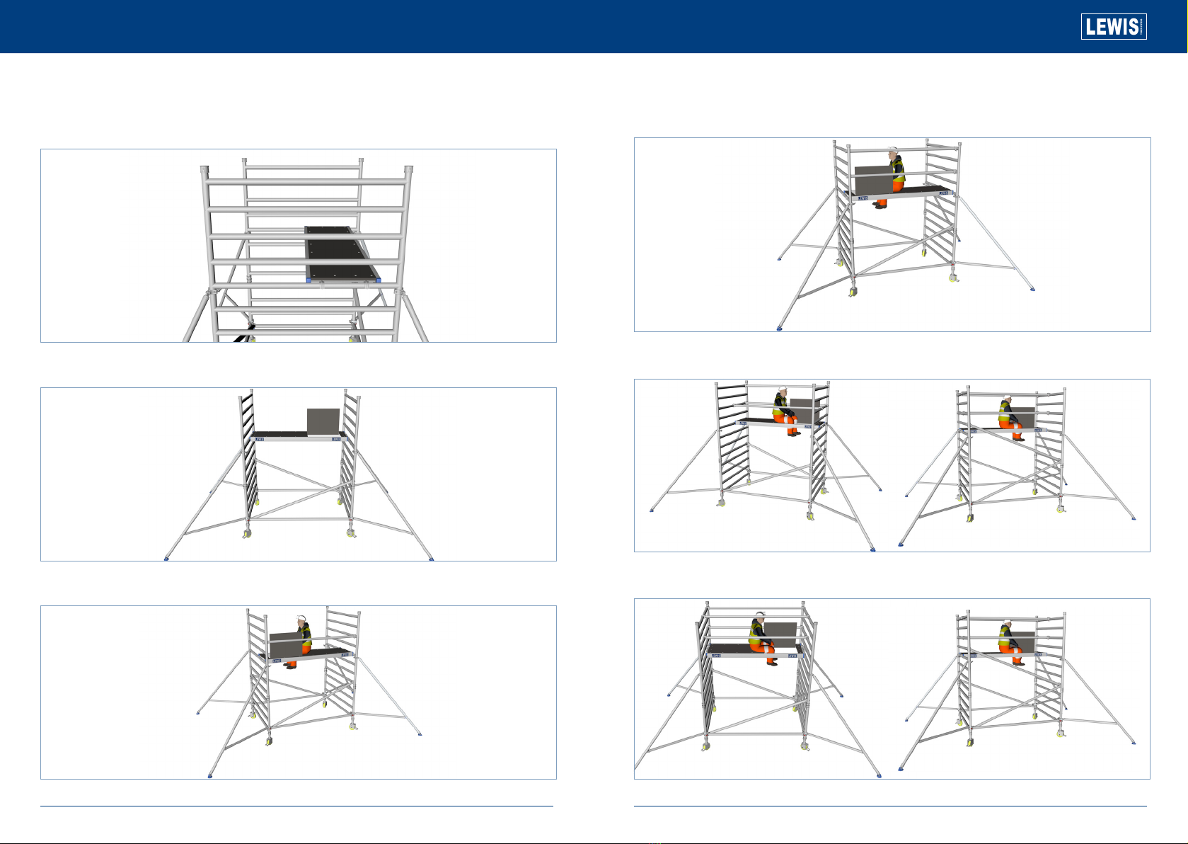
zDuring assembly, the tower should only be climbed from
inside of the frame dimensions, do not scale the tower from
the outside.
zTools and equipment must be loaded onto the platform
within the confines of the tower dimensions.
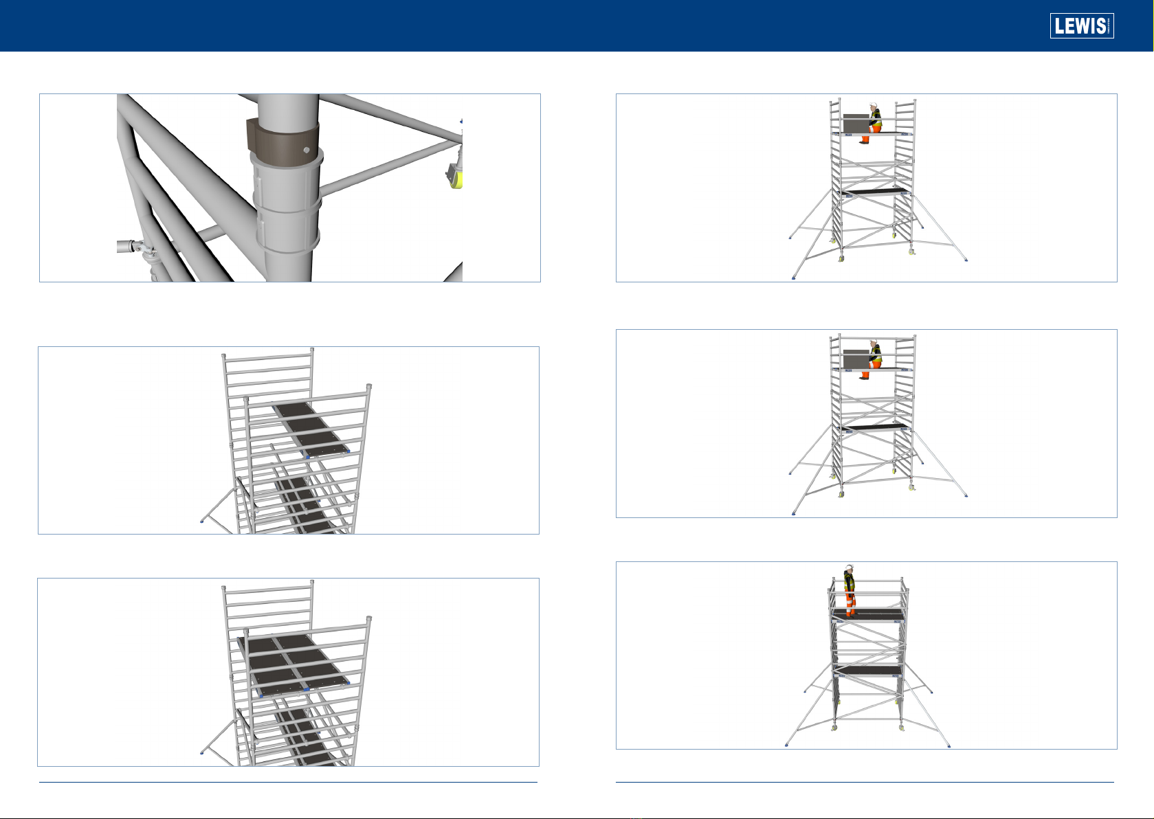
zAdjustable legs are to be used for levelling.
zOutriggers should always be deployed when required.
If the area of operation means that the outriggers cannot be
deployed in the recommended position – contact Lewis Towers
or your supplier for advice.
Ballast for Towers up to 12.2m in height, ballast is not necessary
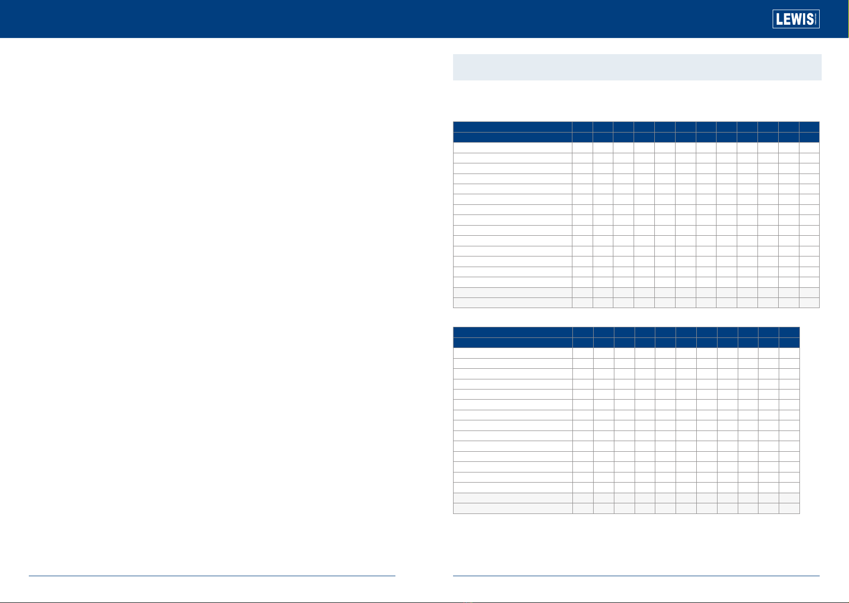
DOUBLE WIDTH INTERNAL AND EXTERNAL USE
Product Information
Working Height in (m) 3.2 3.7 4.2 4.7 5.2 5.7 5.2 6.7 7.2 7.7 8.2 8.7
Platform Height in (m) 1.2 1.7 2.2 2.7 3.2 3.7 4.2 4.7 5.2 5.7 6.2 6.7
150mm Castor 444444444444
Adjustable Leg 500mm 4 4 4 4 4 4 4 4 4 4 4 4
4 Rung 1m Frames 2 2 2 2 2 2
6 Rung 1.5m Frames 2 2 2 2 2 2
8 Rung 2m Frames 2 2 2 4 2 4 4 6 4 6 6
1.8m / 2.5m Fixed Deck 1 1 1 1 1 1 1 1 1 1 1 1
1.8m / 2.5m Trap Deck 1 1 1 1 2 2 2 2 2 2 2 3
1.8 m / 2.5m Horizontal Brace 6 6 6 6 10 10 10 10 10 10 10 14
2.1 m / 2.7m Diagonal Brace 2 2 3 4 5 6 7 8 9 10 11 12
1.8m / 25mm Side Toe Board (Wood) 2 2 2 2 2 2 2 2 2 2 2 2
1.2m End Toe Board (Wood) 2 2 2 2 2 2 2 2 2 2 2 2
Toe Board Clip 4 4 4 4 4 4 4 4 4 4 4
Standard Stabilisers 0044 4444000
Jumbo Stabilisers 0000 0000444
Total Self Weight of Tower (Kg) - 1.8m 92 97 105 128 159 161 174 181 189 201 207 237
Total Self Weight of Tower (Kg) - 2.5m 105 110 119 142 179 190 195 203 211 224 230 266
Working Height in (m) 9.2 9.7 10.2 10.7 11.2 11.7 12.2 12.7 13.2 13.7 14.2
Platform Height in (m) 7.2 7.7 8.2 8.7 9.2 9.7 10.2 10.7 11.2 11.7 12.2
150mm Castor 44444444444
Adjustable Leg 500mm 44444444444
4 Rung 1m Frames 2 2 2 2 2 2
6 Rung 1.5m Frames 22222
8 Rung 2m Frames 868810 810 10 12 10 12
1.8m / 2.5m Fixed Deck 11111111111
1.8m / 2.5m Trap Deck 33333334444
1.8 m / 2.5m Horizontal Brace 14 14 14 14 14 14 14 14 18 18 18
2.1 m / 2.7m Diagonal Brace 13 14 15 16 17 18 19 20 21 22 23
1.8m / 25mm Side Toe Board (Wood) 22222222 22
1.2m End Toe Board (Wood) 22222222 22
Toe Board Clip 44444444 44
Standard Stabilisers 00000000 00
Jumbo Stabilisers 44444444 44
Total Self Weight of Tower (Kg) - 1.8m 250 260 264 290 298 308 313 344 351 359 366
Total Self Weight of Tower (Kg) - 2.5m 279 290 295 317 335 346 351 388 396 404 412