Lexus KMA10 Series User manual

UX300e
KMA10 Series

Foreword
This guide was developed to educate and assist dismantlers in the safe handling of Lexus UX300e electric
vehicles. UX300e dismantling procedures are similar to other non-electric Lexus vehicles with the
exception of the high voltage electrical system. It is important to recognize and understand the high
voltage electrical system features and specifications of the Lexus UX300e electric vehicle, as they may
not be familiar to dismantlers.
High voltage electricity powers the compressor with motor assembly, electric motor, DC/DC converter,
electric heater, and inverter with converter assembly.All other conventional automotive electrical
devices such as the head lights, radio, and gauges are powered from a separate 12 V auxiliary battery.
Numerous safeguards have been designed into the UX300e to help ensure the high voltage, approximately
355.2 V, Lithium-ion (Li-ion) traction battery assembly is kept safe and secure in an accident.
The Li-ion traction battery assembly contains sealed batteries that are similar to rechargeable batteries
used in some battery operated power tools and other consumer products. The electrolyte is absorbed in
the cell plates and will not normally leak out even if the battery is cracked.
High voltage cables, identifiable by orange insulation and connectors, are isolated from the metal chassis
of the vehicle.
Additional topics contained in the guide include:
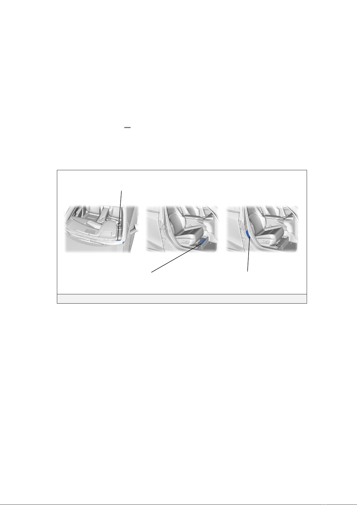
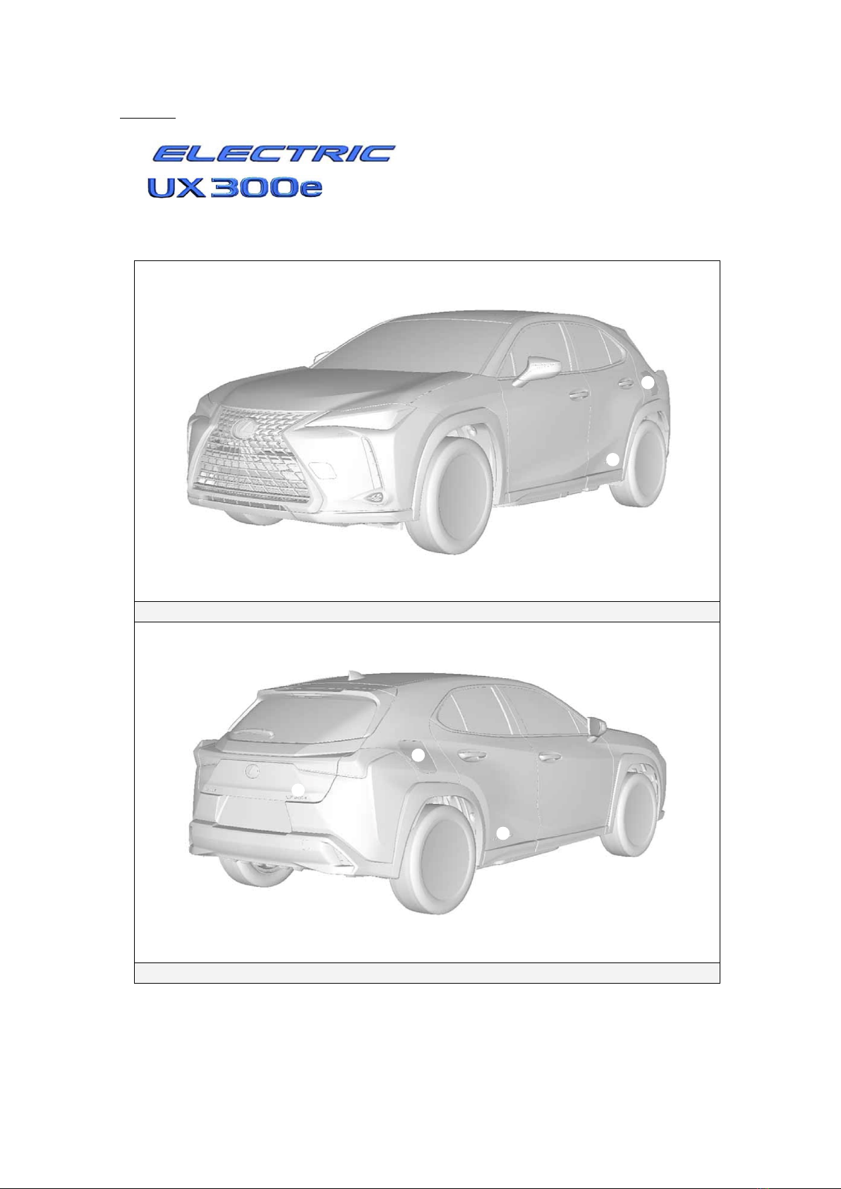
•Lexus UX300e identification.
•Major electric vehicle component locations and descriptions.
By following the information in this guide, dismantlers will be able to handle UX300e electric vehicles as
safely as the dismantling of a conventional non-electric automobile.
2020 Toyota Motor Corporation
All rights reserved. This book may not be reproduced or
copied, in whole or in part, without the written permission
of Toyota Motor Corporation.

Table of Contents
About the UX300e ......................................................................................................................................1
UX300e Identification ................................................................................................................................2
Exterior .........................................................................................................................................................3
Interior...........................................................................................................................................................4
Motor Compartment......................................................................................................................................5
Electric Vehicle Component Locations & Descriptions...........................................................................6
Specifications................................................................................................................................................7
Electric Vehicle Operation.........................................................................................................................8
Vehicle Operation..........................................................................................................................................8
Traction BatteryAssembly andAuxiliary Battery..................................................................................9
Traction Battery Assembly ............................................................................................................................9
Components Powered by the Traction BatteryAssembly .............................................................................9
Traction Battery Assembly Recovery ..........................................................................................................10
Auxiliary Battery..........................................................................................................................................10
High Voltage Safety..................................................................................................................................11
High Voltage Safety System .......................................................................................................................11
Service Plug Grip........................................................................................................................................12
Precaution to be observed when dismantling the vehicle......................................................................13
Necessary Items.........................................................................................................................................13
Spills ..........................................................................................................................................................14
Dismantling the vehicle............................................................................................................................15
Removal of Traction BatteryAssembly..................................................................................................20


1
About the UX300e
The UX300e 5-door hatchback joins the electric vehicle model for Lexus. Electric
Vehicle means that the vehicle contains only an electric motor and does not have a
gasoline engine for power. Electricity is stored in a high voltage traction battery
assembly for the electric motor.
The following illustration demonstrates how the UX300e operates in various driving
modes.
A plug-in charge control system has been adopted, which allows electrical power to
be supplied to the high-capacity traction battery from external power source such as
an electrical socket or charger. The plug-in charge control system supports 2-types
of charging, AC charging and DC charging.
During driving, the vehicle will drive using electric power.
During deceleration, such as when braking, the vehicle regenerates the kinetic
energy from the front wheel to produce electricity that recharges the traction battery
assembly.
While the vehicle is stopped, the electric motor is off, however the vehicle remains
on and operational.
Plug-in Charging
Driving
Deceleration
Stopped
Plug-in Charging
Electricity
Charging batteries

2
UX300e Identification
In appearance, the 2020 model year UX300e is nearly identical to the conventional,
non-electric Lexus UX.The UX300e is a 5-door hatchback.Exterior, interior, and
motor compartment illustrations are provided to assist in identification.
The alphanumeric 15 character Vehicle Identification Number (VIN) is provided on the
left side windshield cowl, floor under the right side front seat and right side B pillar.
Example VIN: JTHAAABH 0000000
A UX300e is identified by the 5th alphanumeric character of the VIN.
Left Side Windshield Cowl, Under the Right Side Front Seat and Right Side B Pillar
Vehicle Identification Number
Certification Label or Name
Vehicle Identification Number

3
Exterior
logos on the each rear door.
logo on the back door.
Charge inlet door located on each rear quarter panel.
Exterior Front and Left Side View
Exterior Rear and Right Side View

4
Interior
The instrument cluster (power meter, READY indicator, plug-in indicator and warning
lights) located in the dash behind the steering wheel, is different than the one on the
conventional, non-electric UX.
NOTICE:
If the vehicle is shut off, the instrument cluster gauges will be “blacked out”, not
illuminated.
Interior View
Combination Meter View
READY Indicator
❹
Plug-in Indicator (for China)
Power Meter

5
Motor Compartment
Orange colored high voltage power cables.
Power Cables

6
Electric Vehicle Component Locations & Descriptions
Component* Location Description
12 Volt Auxiliary
Battery
Driver Side of
Motor
Compartment
A lead-acid battery that supplies power to the low voltage
devices.
Traction Battery
Assembly
Undercarriage
Supplies electrical power to inverter with converter
assembly in accordance with the driving conditions of the
vehicle.
Recharged by electric motor in accordance with the SOC
and the driving conditions of the vehicle.
Accumulates power from the external power source
supplied by plug-in charging.
Power Cables
Undercarriage and
Motor
Compartment
The power cables (HV floor under wire, HV air
conditioning wire, HV battery charger wire,AC charger
inlet cable, DC charger inlet cable, motor cable) are set
of high-voltage, high-amperage cables that connect the
traction battery assembly with the inverter with converter
assembly, the inverter with converter assembly with the
electric motor, and the inverter with converter assembly
with the compressor with motor assembly.
Inverter with
Converter
Assembly
Motor
Compartment
Converts the direct current from the traction battery
assembly into alternating current for electric motor, and
vice versa (from AC to DC).
DC/DC
Converter for
12 Volt
Auxiliary
Battery
Inverter with
Converter
Assembly
Steps down the traction battery nominal voltage of DC
355.2 V to approximately DC 14 V in order to supply
electricity to the electrical components, as well as to
recharge the auxiliary battery.
Electric Motor
Motor
Compartment
Drives by electrical power from the traction battery
assembly, generates motive force for the drive wheels.
Generates high-voltage electricity to recharge the traction
battery, during braking, or when the accelerator pedal is
released.
Compressor with
Motor Assembly
Motor
Compartment
Transmits and receives data between the switches and
sensors.
*Numbers in the component column apply to the illustrations on the following page.

7
Specifications
Electric Motors:
201 hp (150 kW),AC Permanent Magnet Motor
Transmission:
Automatic Only
Traction Battery Assembly:
355.2 Volt Sealed Li-ion Battery
Curb Weight:
3,935-3,968 lbs/1,785-1,800 kg
Frame Material:
Steel Unibody
Body Material:
Steel Panels
Seating Capacity:
5 passenger
●

8
Electric Vehicle Operation
Once the READY indicator is illuminated in the instrument cluster, the vehicle may be
driven. However, as there is no gasoline engine, no sound will be produced from the
vehicle. It is important to recognize and understand the READY indicator provided in
the instrument cluster. When lit, it informs the driver that the vehicle is on and
operational even though the motor compartment is silent.
Vehicle Operation
•With the UX300e, the system is operational while the READY indicator is on.
•Never assume that the vehicle is shut off just because the motor compartment is silent.
Always look for the READY indicator status. The vehicle is shut off when the READY
indicator is off.
Combination Meter READY Indicator
READY Indicator

9
Traction BatteryAssembly and Auxiliary Battery
The UX300e features a high voltage traction battery assembly that contains sealed
Lithium-ion (Li-ion) battery cells.
Traction Battery Assembly
•The traction battery assembly is enclosed in a case and is rigidly mounted under the floor.
The case is isolated from high voltage.
•The traction battery assembly consists of 288 low voltage (3.7 Volt) Li-ion battery cells
connected in series-parallel to produce approximately 355.2 Volts. Each Li-ion battery
cell is non-spillable and sealed in a case.
•The electrolyte used in the Li-ion battery cells is a flammable organic electrolyte. The
electrolyte is absorbed into the battery cell separator and will not normally leak, even in a
collision.
Traction Battery Assembly
Battery assembly voltage
355.2 V
Number of Li-ion battery cells in the battery
288
Li-ion battery cell voltage
3.7 V
Li-ion battery cell dimensions Length x Width x Height
5.83 x 1.04 x 4.09 in.
(148 x 26.5 x 104 mm)
Li-ion battery assembly weight
915 lbs (415kg)
Components Powered by the Traction Battery Assembly
•Electric Motor
•Inverter with Converter Assembly
•Power Cables
•Compressor with Motor Assembly
-DC-DC Converter for 12 Volt Auxiliary Battery

10
Traction Battery Assembly Recovery
•Contact either your Lexus Distributor or the nearest Lexus dealer.
Auxiliary Battery
•The UX300e contains a sealed lead-acid 12 Volts battery. This 12 Volts auxiliary battery
powers the vehicle electrical system similar to a conventional vehicle. As with other
conventional vehicles, the negative terminal of the auxiliary battery is grounded to the metal
chassis of the vehicle.
•The auxiliary battery is located in the motor compartment.
355.2 Volt Traction Battery Assembly
12 VoltAuxiliary Battery Mounted in Motor
Compartment
Traction Battery Assembly Mounted in Under the Floor

11
High Voltage Safety
The traction battery assembly powers the high voltage electrical system with DC electricity.
Positive and negative orange colored high voltage power cables are routed from the traction
battery assembly, under the vehicle floor pan, to the drive unit (inverter and motor) and DC/DC
converter. The inverter contains a circuit that boosts and inverts the 355.2 Volts DC from the
traction battery assembly to 500 Volts AC to power the motor. The inverter with converter
assembly creates 3-phase AC to power the motor. Power cables are routed from the inverter
with converter assembly to each high voltage motor (electric motor, electric heater, and
compressor with motor assembly). The following systems are intended to help keep occupants
in the vehicle and emergency responders safe from high voltage electricity:
High Voltage Safety System
•Positive and negative high voltage power cables * connected to the traction battery
assembly are controlled by 12 Volt normally open relays (system main relays *). When
the vehicle is shut off, the relays stop electrical flow from leaving the traction battery
assembly.
WARNING:
・The high voltage system may remain powered for up to 10
minutes after the vehicle is shut off or disabled. To prevent
serious injury or death from severe burns or electric shock,
avoid touching, cutting, or opening any orange high voltage
power cable or high voltage component.
•Both positive and negative power cables * are insulated from the metal body. High
voltage electricity flows through these cables and not through the metal vehicle body.
The metal vehicle body is safe to touch because it is insulated from the high voltage
components.
•A ground fault monitor in the electric vehicle computer * continuously monitors for high
voltage leakage to the metal chassis while the vehicle is running. If a malfunction is
detected, the electric vehicle computer * will illuminate the master warning light in
the instrument cluster and indicate “EV System Malfunction” on the multi-information
display.
•The traction battery assembly contactors will automatically open to stop electricity flow in a
collision sufficient to activate the SRS.
*Numbers apply to the illustration on the following page.

12
Service Plug Grip
•The high voltage circuit is cut by removing the service plug grip (see page 15).
High Voltage Safety System – Vehicle Shut Off (READY-OFF)
High Voltage Safety System – Vehicle On and Operational (READY-ON)
Charger
Assembly
Compressor with
Motor Assembly
Electric
Heater
Electric Motor
0.0
Volt DC
12 Volt Auxiliary Battery
Inverter with
Converter
Assembly
Battery
Charger
Controller
Battery ECU
Assembly
Electric Vehicle
Computer
AC 3-Phase 0V
0.0
Volt DC
0.0
Volt DC
Volt DC
0.0
Volt DC
Charger
Assembly
Compressor with
Motor Assembly
Electric
Heater
Electric Motor
355.2
Volt DC
12 Volt Auxiliary Battery
Inverter with
Converter
Assembly
Battery
Charger
Controller
Battery ECU
Assembly
Electric Vehicle
Computer
AC 3-Phase
355.2V
0.0
Volt DC 0.0
Volt DC
Volt DC
0.0
Volt DC
➋
➌
➊
➋
➊
➊
355.2
0.0

13
Precaution to be observed when dismantling the vehicle
•To prevent electric shock, wear insulated gloves when working on wire harnesses and components
of the high voltage system.
Before using insulated gloves, be sure to check them for cracks, tears and other types of damage.
•When servicing the vehicle, do not carry metal objects like mechanical pencils or rulers that can be
dropped accidentally and cause a short circuit.
•To reduce the risk of electric shock, make sure to remove the service plug grip to cut off the high
voltage circuit before servicing the vehicle.
•To reduce the risk of electric shock, make sure to wait at least 10 minutes after removing the service
plug grip to fully discharge the high voltage capacitor inside the inverter with converter assembly.
•Do not touch any high voltage wire harnesses, connectors or parts with bare hands.
•Do not touch the terminals of the service plug grip.
•Make sure to insulate the high-voltage connectors and terminals of the traction battery assembly
with insulating tape after removing them.
•After removing the service plug grip, put it in your pocket to prevent other technicians from accident
ally reconnecting it while you are working on the high-voltage system.
•Before touching a bare high-voltage terminal, wear insulated gloves and use a tester to make sure
that the terminal voltage is 0 V.
•Electrolyte leaks may cause acute poisoning if a high concentration of the vapor from the electrolyte
is inhaled. In case of inhalation, move the affected person to a place with ample fresh air and let
them lie quietly. Seek medical care.
•If the electrolyte comes in contact with your skin, wash the area thoroughly with soap and plenty of
water, and seek medical care. If the electrolyte comes in contact with an article of clothing, take it
off immediately. Prolonged contact with the electrolyte may cause skin irritation.
•If the electrolyte comes in contact with your eyes, call out loudly for help. Do not rub your eyes.
Immediately flush them with a large amount of water for at least 15 minutes and seek medical care.
•If electrolyte is swallowed, seek medical care immediately. Do not induce vomiting, unless
instructed by the doctor.
•If the vehicle catches on fire, use an ABC fire extinguisher to extinguish the fire.
Trying to extinguish a fire using only a small amount of water can be more dangerous than effective.
Use a substantial amount of water or wait for firefighters.
•Do not allow any foreign matter or water to enter the traction battery assembly.
Necessary Items
•Protective clothing such as insulated gloves (electrically insulated), rubber gloves, helmet, safety
goggles, safety shoes and SCBA or protective mask.
•Insulating tape such as electrical tape that has a suitable electrical insulation rating and insulation
tool set.
•An electrical tester that is capable of measuring DC 750 Volts or more.

14
Spills
The UX300e contains some of the same common automotive fluids used in other non-electric Lexus
vehicles, with the exception of the Li-ion electrolyte used in the traction battery assembly. The
electrolyte used in the Li-ion battery cells is a flammable organic electrolyte. The electrolyte is
absorbed into the battery cell separators, even if the battery cells are crushed or cracked, it is unlikely
that liquid electrolyte will leak. Any liquid electrolyte that leaks from a Li-ion battery cell quickly
evaporates.
WARNING:
・The Li-ion battery contains organic electrolyte. Only a small
amount may leak from the batteries which may irritate the
eyes, nose, throat, and skin.
・Contact with the vapor produced by the electrolyte may
irritate the nose and throat.
・To avoid injury by coming in contact with the electrolyte or
vapor, wear personal protective equipment for organic
electrolyte including SCBA or protective mask for organic
gases.
Handle Li-ion electrolyte spills using the following Personal Protective Equipment (PPE):
•Splash shield or safety goggles. Fold down helmet shields are not acceptable for
electrolyte spills.
•Butyl rubber or suitable organic solvent gloves.
•Apron or protective clothing suitable for organic solvents.
•Rubber overboots or boots suitable for organic solvents.
•Full face respirator suitable for organic solvents or SCBA.

15
Dismantling the vehicle
The following 5 pages contain general instructions for use when working on a UX300e.
Read these instructions before proceeding to the traction battery assembly removal instructions on page
20.
WARNING:
・The high voltage system may remain powered for up to 10
minutes after the vehicle is shut off or disabled. To prevent
serious injury or death from severe burns or electric shock,
avoid touching, cutting, or opening any orange high voltage
power cable or any high voltage component.
Shut off the ignition (READY indicator is off).
Disconnect cable from negative auxiliary battery terminal.
Loosen the nut and disconnect the cable from the
negative (-) auxiliary battery terminal.
Remove battery service hole cover.
Disengage the 4 clips and remove the battery service
hole cover.
Remove battery service hole cover sub-assembly.
(1) Remove the 4 bolts and battery service hole cover
sub-assembly.

16
Remove No. 2 traction battery cover.
Remove the 4 bolts and No. 2 traction battery cover.
Remove service plug grip.
CAUTION:
・Wear insulated gloves.
・Do not inspect or service the high voltage
system with the service plug grip installed.
・To reduce the risk of electric shock, make sure
to remove the service plug grip to cut off the
high voltage circuit before servicing the
vehicle.
This manual suits for next models
1
Table of contents
Other Lexus Automobile manuals

Lexus
Lexus HYBRID RX400h User manual

Lexus
Lexus SC 430 2001 User manual

Lexus
Lexus GS350 NAVI User manual

Lexus
Lexus GX470 2006 User manual

Lexus
Lexus 2015 CT 200h User manual

Lexus
Lexus RC 350 AWD 2019 User manual

Lexus
Lexus RX500h 2023 User manual

Lexus
Lexus 2015 CT200H User manual

Lexus
Lexus LFA User manual

Lexus
Lexus RX400h 2006 User manual

Lexus
Lexus 2014 RX 350 User manual

Lexus
Lexus RX 350 2014 User manual

Lexus
Lexus RC350 User manual

Lexus
Lexus LC 500 2024 User manual

Lexus
Lexus 2004 LS430 User manual

Lexus
Lexus GS300 1998 User manual

Lexus
Lexus OM30727U User manual

Lexus
Lexus RX450h 2010 User manual

Lexus
Lexus RC F User instructions

Lexus
Lexus RX 450h 2022 User manual